
Installation Guide
Page 6
... to the Switch 3-11 Transceiver Modules 4-1 SFP Modules 4-1 SFP Modules and Alternative Wiring 4-1 X2 Modules 4-2 Module Maintenance Guidelines 4-5 Cleaning the Fiber-Optic Connectors 4-5 Additional Guidelines 4-7 Troubleshooting the Installation 5-1 Getting Started 5-2 Problem Solving to the System Component Level 5-2 Identifying Startup Problems 5-3 LED Readings 5-3 Troubleshooting the Power Supply 5-5 Contacting Customer Service 5-6 Specifications A-1 Console Port A-1 Catalyst 4900 Series Switch Installation Guide...
... to the Switch 3-11 Transceiver Modules 4-1 SFP Modules 4-1 SFP Modules and Alternative Wiring 4-1 X2 Modules 4-2 Module Maintenance Guidelines 4-5 Cleaning the Fiber-Optic Connectors 4-5 Additional Guidelines 4-7 Troubleshooting the Installation 5-1 Getting Started 5-2 Problem Solving to the System Component Level 5-2 Identifying Startup Problems 5-3 LED Readings 5-3 Troubleshooting the Power Supply 5-5 Contacting Customer Service 5-6 Specifications A-1 Console Port A-1 Catalyst 4900 Series Switch Installation Guide...
Installation Guide
Page 9
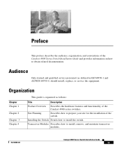
... IEC60950-1 and AZ/NZS 60950-1) should install, replace, or service the equipment. Installing the Switch Details how to install, remove, and maintain transceiver modules. 78-18039-02 Catalyst 4900 Series Switch Installation Guide ix Transceiver Modules Describes how to install the switch. Site Planning Describes how to obtain related documentation. Preface This preface describes the audience...
... IEC60950-1 and AZ/NZS 60950-1) should install, replace, or service the equipment. Installing the Switch Details how to install, remove, and maintain transceiver modules. 78-18039-02 Catalyst 4900 Series Switch Installation Guide ix Transceiver Modules Describes how to install the switch. Site Planning Describes how to obtain related documentation. Preface This preface describes the audience...
Installation Guide
Page 26
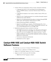
... standard Layer 2 features: 802.1D Spanning Tree, Cisco Discovery Protocol (CDP), VTP version 2 with the Catalyst 4500 series switches - Catalyst 4948-10GE and Catalyst 4928-10GE Switch Software Features Chapter 1 Product Overview • Catalyst 4500 series management software features include the following : - Support for an optional RMON processing module - Embedded CiscoView support Catalyst 4948-10GE and Catalyst 4928-10GE Switch Software Features The following is an overview...
... standard Layer 2 features: 802.1D Spanning Tree, Cisco Discovery Protocol (CDP), VTP version 2 with the Catalyst 4500 series switches - Catalyst 4948-10GE and Catalyst 4928-10GE Switch Software Features Chapter 1 Product Overview • Catalyst 4500 series management software features include the following : - Support for an optional RMON processing module - Embedded CiscoView support Catalyst 4948-10GE and Catalyst 4928-10GE Switch Software Features The following is an overview...
Installation Guide
Page 27
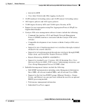
...-port basis without the need for EFM - Support for in -Q for an optional RMON processing module - Support for the first four RMON groups (Ethernet Statistics, Alarms, Events, and History) on all relevant Cisco MIBs - Chapter 1 Product Overview Catalyst 4948-10GE and Catalyst 4928-10GE Switch Software Features - Support for out-of new features with RMON-1 - Performance management information -
...-port basis without the need for EFM - Support for in -Q for an optional RMON processing module - Support for the first four RMON groups (Ethernet Statistics, Alarms, Events, and History) on all relevant Cisco MIBs - Chapter 1 Product Overview Catalyst 4948-10GE and Catalyst 4928-10GE Switch Software Features - Support for out-of new features with RMON-1 - Performance management information -

Installation Guide
Page 37
...panels inaccessible and difficult to maintain. 78-18039-02 Catalyst 4900 Series Switch Installation Guide 2-1 You should install the switch in an enclosed, secure area, ensuring that you complete... all site planning activities before you install the switch. Site Planning 2 C H A P T E R This chapter describes... checklist is provided on page 3-5 to help ensure that only qualified personnel have access to the switch and control of the switch and contains these sections: • Site Environmental Requirements, page 2-1 • Site Power Requirements,...
...panels inaccessible and difficult to maintain. 78-18039-02 Catalyst 4900 Series Switch Installation Guide 2-1 You should install the switch in an enclosed, secure area, ensuring that you complete... all site planning activities before you install the switch. Site Planning 2 C H A P T E R This chapter describes... checklist is provided on page 3-5 to help ensure that only qualified personnel have access to the switch and control of the switch and contains these sections: • Site Environmental Requirements, page 2-1 • Site Power Requirements,...
Installation Guide
Page 45
...damage. Site Planning Checklist Table 2-2 lists the site planning activities that creates a potential hazard to ensure a successful switch installation. 78-18039-02 Catalyst 4900 Series Switch Installation Guide 2-9 always check. • Do not perform any internal components, always use a wrist strap connected to... 10 megohms (Mohms). • Handle cards by the edges only. • Avoid contact between the modules and clothing. The measurement should perform before you install the switch. Any unpainted grounded surface on clothing can result in complete or intermittent failures.
...damage. Site Planning Checklist Table 2-2 lists the site planning activities that creates a potential hazard to ensure a successful switch installation. 78-18039-02 Catalyst 4900 Series Switch Installation Guide 2-9 always check. • Do not perform any internal components, always use a wrist strap connected to... 10 megohms (Mohms). • Handle cards by the edges only. • Avoid contact between the modules and clothing. The measurement should perform before you install the switch. Any unpainted grounded surface on clothing can result in complete or intermittent failures.
Installation Guide
Page 50
...temperature. - Route cables away from other equipment will not obstruct the airflow through the chassis or impair access to the power supplies or switching modules. To prevent airflow restriction, allow at or near the bottom of 104° F (40° C). Ensure that equipment near the ... (7.6 cm) of equipment above, leading to avoid disconnecting cables unnecessarily for equipment maintenance or upgrades. - Catalyst 4900 Series Switch Installation Guide 3-4 78-18039-02 Note that if the switch is mobile, you can push it back within 1 foot (30.45 cm) of clearance behind the rack...
...temperature. - Route cables away from other equipment will not obstruct the airflow through the chassis or impair access to the power supplies or switching modules. To prevent airflow restriction, allow at or near the bottom of 104° F (40° C). Ensure that equipment near the ... (7.6 cm) of equipment above, leading to avoid disconnecting cables unnecessarily for equipment maintenance or upgrades. - Catalyst 4900 Series Switch Installation Guide 3-4 78-18039-02 Note that if the switch is mobile, you can push it back within 1 foot (30.45 cm) of clearance behind the rack...
Installation Guide
Page 61
... relevant documents at the following location: http://www.cisco.com/en/US/products/hw/modules/ps5455/products_device_sup port_tables_list.html SFP Modules and Alternative Wiring The Catalyst 4948 switches have four ports that can be configured with any combination of SFP modules with LC connectors, as shown in the switch software and determines whether the SFP or the RJ...
... relevant documents at the following location: http://www.cisco.com/en/US/products/hw/modules/ps5455/products_device_sup port_tables_list.html SFP Modules and Alternative Wiring The Catalyst 4948 switches have four ports that can be configured with any combination of SFP modules with LC connectors, as shown in the switch software and determines whether the SFP or the RJ...
Installation Guide
Page 62
... 4-1 Connecting LC Connectors to the 10-Gigabit Ethernet Transceiver Modules Compatibility Matrix at the following location: http://www.cisco.com/en/US/products/hw/modules/ps5455/prod_installation_gu ide09186a00803469ed.html For compatibility information, refer to the SFP Module (Catalyst 4948) Catalyst 4948 113146 CON AUX 45 46 47 48 X2 Modules You must insert the SFP with the latching mechanism...
... 4-1 Connecting LC Connectors to the 10-Gigabit Ethernet Transceiver Modules Compatibility Matrix at the following location: http://www.cisco.com/en/US/products/hw/modules/ps5455/prod_installation_gu ide09186a00803469ed.html For compatibility information, refer to the SFP Module (Catalyst 4948) Catalyst 4948 113146 CON AUX 45 46 47 48 X2 Modules You must insert the SFP with the latching mechanism...

Installation Guide
Page 63
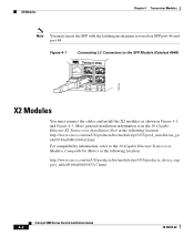
Chapter 4 Transceiver Modules X2 Modules Figure 4-2 Connecting SC Connectors to the X2 Module Catalyst WS-C4948 10GE X2-1 X2-2 CON MGT 130088 If a module designed for more information. 78-18039-02 Catalyst 4900 Series Switch Installation Guide 4-3 See the Catalyst 4500 Series Module Installation Guide for operation on an SMF cable is directly coupled to an MMF cable, an effect known as Differential Mode Delay (DMD) might occur.
Chapter 4 Transceiver Modules X2 Modules Figure 4-2 Connecting SC Connectors to the X2 Module Catalyst WS-C4948 10GE X2-1 X2-2 CON MGT 130088 If a module designed for more information. 78-18039-02 Catalyst 4900 Series Switch Installation Guide 4-3 See the Catalyst 4500 Series Module Installation Guide for operation on an SMF cable is directly coupled to an MMF cable, an effect known as Differential Mode Delay (DMD) might occur.
Installation Guide
Page 64
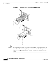
For either the top or bottom connector, forcing a module could potentially damage both the module and the switch. Catalyst 4900 Series Switch Installation Guide 4-4 78-18039-02 X2 Modules Chapter 4 Transceiver Modules Figure 4-3 Installing the 10-Gigabit Ethernet X2 Module Catalyst WS-C4948 10GE CON X1 MGT LINK X2 Catalyst WS-C4948 10GE CON X1 MGT X2 130091 Caution If you attempt to insert the bottom X2 module with the cooling fins pointing up, you will probably permanently damage the connector.
For either the top or bottom connector, forcing a module could potentially damage both the module and the switch. Catalyst 4900 Series Switch Installation Guide 4-4 78-18039-02 X2 Modules Chapter 4 Transceiver Modules Figure 4-3 Installing the 10-Gigabit Ethernet X2 Module Catalyst WS-C4948 10GE CON X1 MGT LINK X2 Catalyst WS-C4948 10GE CON X1 MGT X2 130091 Caution If you attempt to insert the bottom X2 module with the cooling fins pointing up, you will probably permanently damage the connector.
Installation Guide
Page 65
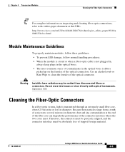
Warning Invisible laser radiation may be absolutely free of trapped foreign material. 78-18039-02 Catalyst 4900 Series Switch Installation Guide 4-5 Statement 1051 Cleaning the Fiber-Optic Connectors In a fiber-optic system, light is transmitted through an...emitted from a tenth of a micron to the white-paper document at this URL: http://www.cisco.com/en/US/tech/tk482/tk876/technologies_white_paper09186a 0080254eba.shtml Module Maintenance Guidelines To properly maintain modules, follow these guidelines: • To prevent ESD damage, follow normal handling procedures. • ...
Warning Invisible laser radiation may be absolutely free of trapped foreign material. 78-18039-02 Catalyst 4900 Series Switch Installation Guide 4-5 Statement 1051 Cleaning the Fiber-Optic Connectors In a fiber-optic system, light is transmitted through an...emitted from a tenth of a micron to the white-paper document at this URL: http://www.cisco.com/en/US/tech/tk482/tk876/technologies_white_paper09186a 0080254eba.shtml Module Maintenance Guidelines To properly maintain modules, follow these guidelines: • To prevent ESD damage, follow normal handling procedures. • ...
Installation Guide
Page 66
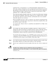
Cleaning the Fiber-Optic Connectors Chapter 4 Transceiver Modules Connector loss, or insertion loss, is a critical performance characteristic of light loss. To clean the optical connectors, use . Statement 1051 Catalyst 4900 Series Switch Installation Guide 4-6 78-18039-02 the lower the reflection, the better the connection. Dirty fiber connectors are not in 99 percent pure...
Cleaning the Fiber-Optic Connectors Chapter 4 Transceiver Modules Connector loss, or insertion loss, is a critical performance characteristic of light loss. To clean the optical connectors, use . Statement 1051 Catalyst 4900 Series Switch Installation Guide 4-6 78-18039-02 the lower the reflection, the better the connection. Dirty fiber connectors are not in 99 percent pure...
Installation Guide
Page 67
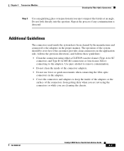
... follows these guidelines: • Clean the connectors using the connectors or while you are cleaning the chassis. 78-18039-02 Catalyst 4900 Series Switch Installation Guide 4-7 Do not look directly into the aperture. Repeat the process if any contamination is detected. The operation of ... adapters. • Do not use force or quick movements when connecting the fiber-optic connectors in the proper manner. Chapter 4 Transceiver Modules Cleaning the Fiber-Optic Connectors Step 3 Use a magnifying glass or inspection microscope to the adapters in the adapters. • Cover the...
... follows these guidelines: • Clean the connectors using the connectors or while you are cleaning the chassis. 78-18039-02 Catalyst 4900 Series Switch Installation Guide 4-7 Do not look directly into the aperture. Repeat the process if any contamination is detected. The operation of ... adapters. • Do not use force or quick movements when connecting the fiber-optic connectors in the proper manner. Chapter 4 Transceiver Modules Cleaning the Fiber-Optic Connectors Step 3 Use a magnifying glass or inspection microscope to the adapters in the adapters. • Cover the...

Installation Guide
Page 68
Cleaning the Fiber-Optic Connectors Chapter 4 Transceiver Modules Catalyst 4900 Series Switch Installation Guide 4-8 78-18039-02
Cleaning the Fiber-Optic Connectors Chapter 4 Transceiver Modules Catalyst 4900 Series Switch Installation Guide 4-8 78-18039-02
Installation Guide
Page 73
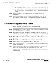
... is red, unplug the power cord, and then plug the power cord in. If the LED fails to light after you are green when the module is operational (online). The port LED flashes yellow if the port tested faulty at the power supply LED (PS1 or PS2). Connect the power cord.... If the LED is off . The port LED remains yellow if the port is red, contact a customer service representative for instructions. 78-18039-02 Catalyst 4900 Series Switch Installation Guide 5-5 If a STATUS LED is disabled. If the LED then lights, the problem is off or if the LED is an AC supply...
... is red, unplug the power cord, and then plug the power cord in. If the LED fails to light after you are green when the module is operational (online). The port LED flashes yellow if the port tested faulty at the power supply LED (PS1 or PS2). Connect the power cord.... If the LED is off . The port LED remains yellow if the port is red, contact a customer service representative for instructions. 78-18039-02 Catalyst 4900 Series Switch Installation Guide 5-5 If a STATUS LED is disabled. If the LED then lights, the problem is off or if the LED is an AC supply...