
Hardware Installation Guide
Page 2
... A devices: This equipment has been tested and found to radio or television communications at their own expense. These specifications are designed to operate the product. You can radiate radio-frequency energy and, if not installed and used in ... © 1981, Regents of the University of Cisco Systems, Inc. and Aironet, ASIST, BPX, Catalyst, CCDA, CCDP, CCIE, CCNA, CCNP, Cisco, the Cisco Certified Internetwork Expert logo, Cisco IOS, the Cisco IOS logo, Cisco Press, Cisco Systems, Cisco Systems Capital, the Cisco Systems logo, Empowering the Internet Generation, Enterprise/Solver...
... A devices: This equipment has been tested and found to radio or television communications at their own expense. These specifications are designed to operate the product. You can radiate radio-frequency energy and, if not installed and used in ... © 1981, Regents of the University of Cisco Systems, Inc. and Aironet, ASIST, BPX, Catalyst, CCDA, CCDP, CCIE, CCNA, CCNP, Cisco, the Cisco Certified Internetwork Expert logo, Cisco IOS, the Cisco IOS logo, Cisco Press, Cisco Systems, Cisco Systems Capital, the Cisco Systems logo, Empowering the Internet Generation, Enterprise/Solver...

Hardware Installation Guide
Page 7
... 2-19 Installing the Switch on a Wall 2-20 Attaching the Brackets to the Switch 2-21 Mounting the Switch to a Wall 2-22 Powering On the Switch and Running POST 2-24 Connecting to DC Power 2-25 Preparing for Installation 2-25 Grounding the Switch 2-26 Wiring the... Go Next 2-43 Troubleshooting 3-1 Understanding POST Results 3-1 Correcting Module POST Failures 3-2 Diagnosing Problems 3-3 Technical Specifications A-1 Connectors and Cable Specifications B-1 Connector Specifications B-1 10/100 Ports B-1 100BASE-FX Ports B-2 Contents 78-6461-04 Catalyst 2900 Series XL Hardware Installation Guide vii
... 2-19 Installing the Switch on a Wall 2-20 Attaching the Brackets to the Switch 2-21 Mounting the Switch to a Wall 2-22 Powering On the Switch and Running POST 2-24 Connecting to DC Power 2-25 Preparing for Installation 2-25 Grounding the Switch 2-26 Wiring the... Go Next 2-43 Troubleshooting 3-1 Understanding POST Results 3-1 Correcting Module POST Failures 3-2 Diagnosing Problems 3-3 Technical Specifications A-1 Connectors and Cable Specifications B-1 Connector Specifications B-1 10/100 Ports B-1 100BASE-FX Ports B-2 Contents 78-6461-04 Catalyst 2900 Series XL Hardware Installation Guide vii

Hardware Installation Guide
Page 8
... Ports B-3 Console Port B-3 Cable and Adapter Specifications B-4 Crossover and Straight-Through Cable Pinouts B-4 RJ-21 Cable Pinouts B-5 Console Port B-5 Identifying a Rollover Cable B-6 Connecting to a PC B-6 Connecting to a Terminal B-7 Translated Safety Warnings C-1 Attaching the Cisco RPS (model PWR600-AC-RPS) C-1 Attaching the Cisco RPS (model PWR300-AC-RPS-N1) C-2 Qualified... C-14 Supply Circuit Warning C-15 Voltage Warning C-16 Power Supply Warning C-17 Lightning Activity Warning C-19 Product Disposal Warning C-21 Catalyst 2900 Series XL Hardware Installation Guide viii 78-6461-04
... Ports B-3 Console Port B-3 Cable and Adapter Specifications B-4 Crossover and Straight-Through Cable Pinouts B-4 RJ-21 Cable Pinouts B-5 Console Port B-5 Identifying a Rollover Cable B-6 Connecting to a PC B-6 Connecting to a Terminal B-7 Translated Safety Warnings C-1 Attaching the Cisco RPS (model PWR600-AC-RPS) C-1 Attaching the Cisco RPS (model PWR300-AC-RPS-N1) C-2 Qualified... C-14 Supply Circuit Warning C-15 Voltage Warning C-16 Power Supply Warning C-17 Lightning Activity Warning C-19 Product Disposal Warning C-21 Catalyst 2900 Series XL Hardware Installation Guide viii 78-6461-04

Hardware Installation Guide
Page 11
... that you are familiar with the concepts and terminology of Ethernet and local area networking. We assume that might arise when you are installing the switch. 78-6461-04 Catalyst 2900 Series XL Hardware Installation Guide xi Chapter 3, "Troubleshooting," describes how to install a switch, and provides troubleshooting information and specifications.
... that you are familiar with the concepts and terminology of Ethernet and local area networking. We assume that might arise when you are installing the switch. 78-6461-04 Catalyst 2900 Series XL Hardware Installation Guide xi Chapter 3, "Troubleshooting," describes how to install a switch, and provides troubleshooting information and specifications.

Hardware Installation Guide
Page 12
Appendix C, "Translated Safety Warnings," provides translations in various languages of data. Catalyst 2900 Series XL Hardware Installation Guide xii 78-6461-04 Notes, cautions, and warnings use these conventions: • Terminal ... used to connect to convey instructions and information: Command descriptions use the following conventions to the switch. In this situation, you might do something that can be careful. Appendix B, "Connectors and Cable Specifications," describes the connectors, cables, and adapters that could result in italic. Conventions Preface Appendix A,...
Appendix C, "Translated Safety Warnings," provides translations in various languages of data. Catalyst 2900 Series XL Hardware Installation Guide xii 78-6461-04 Notes, cautions, and warnings use these conventions: • Terminal ... used to connect to convey instructions and information: Command descriptions use the following conventions to the switch. In this situation, you might do something that can be careful. Appendix B, "Connectors and Cable Specifications," describes the connectors, cables, and adapters that could result in italic. Conventions Preface Appendix A,...

Hardware Installation Guide
Page 18
... using the product-specific CD and you are connected to help customers and partners streamline business processes and improve productivity. Obtaining Technical Assistance Cisco provides Cisco.com as a starting point for this platform, click Give Us Your Feedback. Cisco.com Cisco.com is a ...mail, for doing business with Cisco. You can find information about Cisco and our networking solutions, xviii Catalyst 2900 Series XL Hardware Installation Guide 78-6461-04 Click Submit to the following address: Cisco Systems, Inc. For Cisco.com registered users, additional troubleshooting...
... using the product-specific CD and you are connected to help customers and partners streamline business processes and improve productivity. Obtaining Technical Assistance Cisco provides Cisco.com as a starting point for this platform, click Give Us Your Feedback. Cisco.com Cisco.com is a ...mail, for doing business with Cisco. You can find information about Cisco and our networking solutions, xviii Catalyst 2900 Series XL Hardware Installation Guide 78-6461-04 Click Submit to the following address: Cisco Systems, Inc. For Cisco.com registered users, additional troubleshooting...
Hardware Installation Guide
Page 19
... capabilities, product installation, or basic product configuration. In each of an order, access technical support, and view benefits specific to the following website: http://www.cisco.com/register/ 78-6461-04 Catalyst 2900 Series XL Hardware Installation Guide xix Network functionality is noticeably impaired, but most business operations continue. • P4-You need...
... capabilities, product installation, or basic product configuration. In each of an order, access technical support, and view benefits specific to the following website: http://www.cisco.com/register/ 78-6461-04 Catalyst 2900 Series XL Hardware Installation Guide xix Network functionality is noticeably impaired, but most business operations continue. • P4-You need...

Hardware Installation Guide
Page 24
...Simple network management protocol (SNMP)-SNMP provides a means to the Catalyst 2900 Series XL and Catalyst 3500 Series XL Software Configuration Guide. You can have a set of LEDs and a Mode button. Catalyst 2900 Series XL Hardware Installation Guide 1-4 78-6461-04 For more... Description Depending on the switch. You can also display network topologies to gather link information and to display switch images to modify switch- You can fully configure and monitor a standalone switch, a specific cluster member, or an entire switch cluster. The switch supports a comprehensive set of...
...Simple network management protocol (SNMP)-SNMP provides a means to the Catalyst 2900 Series XL and Catalyst 3500 Series XL Software Configuration Guide. You can have a set of LEDs and a Mode button. Catalyst 2900 Series XL Hardware Installation Guide 1-4 78-6461-04 For more... Description Depending on the switch. You can also display network topologies to gather link information and to display switch images to modify switch- You can fully configure and monitor a standalone switch, a specific cluster member, or an entire switch cluster. The switch supports a comprehensive set of...

Hardware Installation Guide
Page 26
...switch ports can be sure that both devices support and full-duplex transmission if the attached device supports it) and configures itself accordingly. For more information about these features. Cisco IP Phones-connected to operate in Appendix B, "Connectors and Cable Specifications." Pinouts for Cisco... 4, or 5 cabling • 100BASE-TX-compatible devices, such as high-speed workstations, Cisco IP Phones, servers, hubs, routers, and other switches through , twisted-pair cable. Catalyst 2900 Series XL Hardware Installation Guide 1-6 78-6461-04 These ports also can use a ...
...switch ports can be sure that both devices support and full-duplex transmission if the attached device supports it) and configures itself accordingly. For more information about these features. Cisco IP Phones-connected to operate in Appendix B, "Connectors and Cable Specifications." Pinouts for Cisco... 4, or 5 cabling • 100BASE-TX-compatible devices, such as high-speed workstations, Cisco IP Phones, servers, hubs, routers, and other switches through , twisted-pair cable. Catalyst 2900 Series XL Hardware Installation Guide 1-6 78-6461-04 These ports also can use a ...

Hardware Installation Guide
Page 33
... but is unavailable because it is providing power to another device (redundancy has been allocated to the appropriate switch documentation for redundant power system (RPS) descriptions specific for the switch. RPS is off or not properly connected. Table 1-3 RPS LED on the RPS puts it restarts. RPS...Note This is not installed. Chapter 1 Product Overview Front-Panel Description RPS LED The Catalyst 2912 LRE XL and Catalyst 2924 LRE XL switches use the Cisco RPS 600 (model PWR600-AC-RPS). The switch goes through its normal boot sequence when it in Ready mode, and the LED should...
... but is unavailable because it is providing power to another device (redundancy has been allocated to the appropriate switch documentation for redundant power system (RPS) descriptions specific for the switch. RPS is off or not properly connected. Table 1-3 RPS LED on the RPS puts it restarts. RPS...Note This is not installed. Chapter 1 Product Overview Front-Panel Description RPS LED The Catalyst 2912 LRE XL and Catalyst 2924 LRE XL switches use the Cisco RPS 600 (model PWR600-AC-RPS). The switch goes through its normal boot sequence when it in Ready mode, and the LED should...

Hardware Installation Guide
Page 42
... is not in the RPS documentation. Cisco RPS Connector Specific Cisco RPS models support specific Catalyst 2900 XL switches: • Cisco RPS 600 (model PWR600-AC-RPS)-supports the Catalyst 2912 XL, 2924C XL, 2924 XL, 2924MF XL, and 2924M XL switches. • Cisco RPS 300 (model PWR300-AC-RPS-N1)-supports the Catalyst 2912 LRE XL and 2924 LRE XL...
... is not in the RPS documentation. Cisco RPS Connector Specific Cisco RPS models support specific Catalyst 2900 XL switches: • Cisco RPS 600 (model PWR600-AC-RPS)-supports the Catalyst 2912 XL, 2924C XL, 2924 XL, 2924MF XL, and 2924M XL switches. • Cisco RPS 300 (model PWR300-AC-RPS-N1)-supports the Catalyst 2912 LRE XL and 2924 LRE XL...

Hardware Installation Guide
Page 51
... materials to the modules documentation in Appendix A, "Technical Specifications." • Airflow around the switch and through the vents is away from the shipping container, and check each item for unrestricted cabling. - Your Catalyst 2900 XL switch is within the ranges listed in the Related Publications, ...(LRE) ports, cable lengths from the switch to the connected Ethernet device are up to Find the Catalyst 2900 XL and Catalyst 3500 XL Documentation flyer • Cisco Documentation CD-ROM • AC power cord 78-6461-04 Catalyst 2900 Series XL Hardware Installation Guide 2-7 ...
... materials to the modules documentation in Appendix A, "Technical Specifications." • Airflow around the switch and through the vents is away from the shipping container, and check each item for unrestricted cabling. - Your Catalyst 2900 XL switch is within the ranges listed in the Related Publications, ...(LRE) ports, cable lengths from the switch to the connected Ethernet device are up to Find the Catalyst 2900 XL and Catalyst 3500 XL Documentation flyer • Cisco Documentation CD-ROM • AC power cord 78-6461-04 Catalyst 2900 Series XL Hardware Installation Guide 2-7 ...

Hardware Installation Guide
Page 79
...Specifications" section on the front panel (Figure 2-28). When connecting to a 10/100 Port 74080 CONSOLE BERFEOFREERPOCTOWONEMNRAENCUTAINL G DC INPUT ICNUPRURTE: 3N6T:- 72 4-2A A +- B +- To maximize performance, choose one of these steps to connect to 10BASE-T and 100BASE-TX devices: Step 1 When connecting to workstations, servers, routers, and Cisco...Terminal block plug Tie wrap Connecting to a 10/100 Port The switch 10/100 ports configure themselves to an RJ-45 connector on page B-4. 78-6461-04 Catalyst 2900 Series XL Hardware Installation Guide 2-35 If the attached ports ...
...Specifications" section on the front panel (Figure 2-28). When connecting to a 10/100 Port 74080 CONSOLE BERFEOFREERPOCTOWONEMNRAENCUTAINL G DC INPUT ICNUPRURTE: 3N6T:- 72 4-2A A +- B +- To maximize performance, choose one of these steps to connect to 10BASE-T and 100BASE-TX devices: Step 1 When connecting to workstations, servers, routers, and Cisco...Terminal block plug Tie wrap Connecting to a 10/100 Port The switch 10/100 ports configure themselves to an RJ-45 connector on page B-4. 78-6461-04 Catalyst 2900 Series XL Hardware Installation Guide 2-35 If the attached ports ...

Hardware Installation Guide
Page 86
... about installing and connecting to modules in the Catalyst 2924M XL and 2912MF XL module slots, refer to the switch console port. For console port and adapter pinout information, see the "Cable and Adapter Specifications" section on page B-4. or terminal-emulation software...Cisco. You can change the port baud rate to a terminal. The PC or terminal must support VT100 terminal emulation. The terminal-emulation software-frequently a PC application such as Hyperterminal or Procomm Plus-makes communication between the switch and your PC- See the Catalyst 2900 Series XL and Catalyst...
... about installing and connecting to modules in the Catalyst 2924M XL and 2912MF XL module slots, refer to the switch console port. For console port and adapter pinout information, see the "Cable and Adapter Specifications" section on page B-4. or terminal-emulation software...Cisco. You can change the port baud rate to a terminal. The PC or terminal must support VT100 terminal emulation. The terminal-emulation software-frequently a PC application such as Hyperterminal or Procomm Plus-makes communication between the switch and your PC- See the Catalyst 2900 Series XL and Catalyst...

Hardware Installation Guide
Page 99
Table A-6 lists the agency approvals for the Catalyst 2900 series switches. A A P P E N D I X Technical Specifications Table A-1, Table A-2, Table A-3, and Table A-5 list the technical specifications for EMI and safety. 78-6461-04 Catalyst 2900 Series XL Hardware Installation Guide A-1 For switches that support modules (Catalyst 2912MF XL and 2924M XL), also refer to the Catalyst 2900 Series XL Modules Installation Guide and the Catalyst 2900 Series XL ATM Modules Installation Guide for additional specifications.
Table A-6 lists the agency approvals for the Catalyst 2900 series switches. A A P P E N D I X Technical Specifications Table A-1, Table A-2, Table A-3, and Table A-5 list the technical specifications for EMI and safety. 78-6461-04 Catalyst 2900 Series XL Hardware Installation Guide A-1 For switches that support modules (Catalyst 2912MF XL and 2924M XL), also refer to the Catalyst 2900 Series XL Modules Installation Guide and the Catalyst 2900 Series XL ATM Modules Installation Guide for additional specifications.
Hardware Installation Guide
Page 100
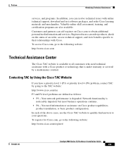
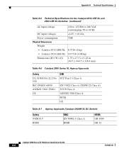
Appendix A Technical Specifications Table A-1 Technical Specifications for the Catalyst 2912 XL and Catalyst 2912MF XL Switches Environmental Ranges Operating temperature Storage temperature Operating humidity Operating altitude Storage altitude Power Requirements AC input voltage DC input voltages Catalyst 2912 XL 32 to 113°F (0 to 45°C) -4 ...(maximum) 239 Btus per hour 7 lb (3.2 kg) Dimensions (H x W x D) 1.73 x 17.5 x 9.79 in. (4.4 x 44.5 x 24.8 cm) Catalyst 2912MF XL 32 to 113°F (0 to 45°C) -4 to 149°F (-10 to 65°C) 10 to 85% (noncondensing) Up to 10,000 ft...
Appendix A Technical Specifications Table A-1 Technical Specifications for the Catalyst 2912 XL and Catalyst 2912MF XL Switches Environmental Ranges Operating temperature Storage temperature Operating humidity Operating altitude Storage altitude Power Requirements AC input voltage DC input voltages Catalyst 2912 XL 32 to 113°F (0 to 45°C) -4 ...(maximum) 239 Btus per hour 7 lb (3.2 kg) Dimensions (H x W x D) 1.73 x 17.5 x 9.79 in. (4.4 x 44.5 x 24.8 cm) Catalyst 2912MF XL 32 to 113°F (0 to 45°C) -4 to 149°F (-10 to 65°C) 10 to 85% (noncondensing) Up to 10,000 ft...

Hardware Installation Guide
Page 101
... nanometers 2. receiver Optical power transmitter - wavelength Optical sensibility of the - Appendix A Technical Specifications Table A-2 Technical Specifications for the Catalyst 2924 XL and Catalyst 2924C XL Switches Catalyst 2924 XL Environmental Operating Ranges Operating temperature 32 to 113°F (0 to 45°C) ...D) Fiber-Port Power Levels 1.73 x 17.5 x 9.79 in. (4.4 x 44.5 x 24.8 cm) Optical transmitter - Transmit - 1. dBm = decibel milliwatt Catalyst 2924C XL 32 to 113°F (0 to 45°C) -4 to 149°F (-10 to 65°C) 10 to 85% (noncondensing) Up to 10,000 ...
... nanometers 2. receiver Optical power transmitter - wavelength Optical sensibility of the - Appendix A Technical Specifications Table A-2 Technical Specifications for the Catalyst 2924 XL and Catalyst 2924C XL Switches Catalyst 2924 XL Environmental Operating Ranges Operating temperature 32 to 113°F (0 to 45°C) ...D) Fiber-Port Power Levels 1.73 x 17.5 x 9.79 in. (4.4 x 44.5 x 24.8 cm) Optical transmitter - Transmit - 1. dBm = decibel milliwatt Catalyst 2924C XL 32 to 113°F (0 to 45°C) -4 to 149°F (-10 to 65°C) 10 to 85% (noncondensing) Up to 10,000 ...
Hardware Installation Guide
Page 102
Appendix A Technical Specifications Table A-3 Technical Specifications for the Catalyst 2924M XL Switches Environmental Operating Ranges Operating temperature 32 to 113°F (0 to 45°C) Storage temperature -4 to 149°F (-10 to 65°C) Operating humidity 10 to ... Btus per hour Physical Dimensions Weight 13.5 lb (6.12 kg) 15 lb (6.8 kg) with two modules installed Dimensions (H x W x D) 3.46 x 17.5 x 12 in. (8.8 x 44.5 x 30.5 cm) Catalyst 2900 Series XL Hardware Installation Guide A-4 78-6461-04
Appendix A Technical Specifications Table A-3 Technical Specifications for the Catalyst 2924M XL Switches Environmental Operating Ranges Operating temperature 32 to 113°F (0 to 45°C) Storage temperature -4 to 149°F (-10 to 65°C) Operating humidity 10 to ... Btus per hour Physical Dimensions Weight 13.5 lb (6.12 kg) 15 lb (6.8 kg) with two modules installed Dimensions (H x W x D) 3.46 x 17.5 x 12 in. (8.8 x 44.5 x 30.5 cm) Catalyst 2900 Series XL Hardware Installation Guide A-4 78-6461-04
Hardware Installation Guide
Page 103
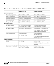
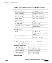
...Technical Specifications for Catalyst 2924M XL DC Switches Environmental Ranges Operating temperature Storage temperature Operating humidity Operating altitude Storage altitude Power Requirements Power consumption DC input voltage Wire gauge for the Catalyst 2912 LRE XL and 2924 LRE XL Switches ...(6.12 kg) 15 lb (6.8 kg) with two modules installed 3.46 x 17.5 x 12 in. (8.8 x 44.5 x 30.5 cm) Table A-5 Technical Specifications for power connection Branch circuit protection Physical Dimensions Weight Dimensions (H x W x D) 1. AWG = American Wire Gauge 32 to 113°F (0 to 45°...
...Technical Specifications for Catalyst 2924M XL DC Switches Environmental Ranges Operating temperature Storage temperature Operating humidity Operating altitude Storage altitude Power Requirements Power consumption DC input voltage Wire gauge for the Catalyst 2912 LRE XL and 2924 LRE XL Switches ...(6.12 kg) 15 lb (6.8 kg) with two modules installed 3.46 x 17.5 x 12 in. (8.8 x 44.5 x 30.5 cm) Table A-5 Technical Specifications for power connection Branch circuit protection Physical Dimensions Weight Dimensions (H x W x D) 1. AWG = American Wire Gauge 32 to 113°F (0 to 45°...
Hardware Installation Guide
Page 104
... A Technical Specifications Table A-5 Technical Specifications for the Catalyst 2912 LRE XL and 2924 LRE XL Switches (continued) AC input voltage 100 to 127/200 to 240 VAC (autoranging) 50 to 60 Hz DC input voltages +12V @12A Power consumption 70W Physical Dimensions Weight • Catalyst 2912 LRE XL 8.75 lb (4 kg) • Catalyst 2924 LRE XL..., TS001 CE EMI FCC Part 15 Class A EN 55022 Class A (CISPR 22 Class A) VCCI Class A AS/NZS 3548 Class A BCIQ CE Table A-7 Agency Approvals (Catalyst 2924M XL DC Switch) Safety NOM 019 BSMI EMC EN 50082-1 Class A BSMI NEBS GR-1089 GR-63...
... A Technical Specifications Table A-5 Technical Specifications for the Catalyst 2912 LRE XL and 2924 LRE XL Switches (continued) AC input voltage 100 to 127/200 to 240 VAC (autoranging) 50 to 60 Hz DC input voltages +12V @12A Power consumption 70W Physical Dimensions Weight • Catalyst 2912 LRE XL 8.75 lb (4 kg) • Catalyst 2924 LRE XL..., TS001 CE EMI FCC Part 15 Class A EN 55022 Class A (CISPR 22 Class A) VCCI Class A AS/NZS 3548 Class A BCIQ CE Table A-7 Agency Approvals (Catalyst 2924M XL DC Switch) Safety NOM 019 BSMI EMC EN 50082-1 Class A BSMI NEBS GR-1089 GR-63...