
Hardware Installation Guide
Page 6
... 1-14 Module Slot LEDs 1-19 Rear-Panel Description 1-19 Power Connectors 1-21 Internal Power Supply Connector 1-21 DC Power Connector 1-21 Cisco RPS Connector 1-22 Console Port... 1-23 2 C H A P T E R Installation 2-1 Preparing for Installation 2-1 Warnings 2-1 EMC Regulatory Statements 2-4 U.S.A. 2-4 Taiwan 2-4 Japan 2-5 Korea 2-5 Hungary 2-6 Installation Guidelines 2-6 Verifying Package Contents 2-7 Installing the Switch on a Table or Shelf 2-9 Installing the Switch in a Rack 2-9 Removing Screws from the Switch 2-11 Attaching the Brackets to a Catalyst...
... 1-14 Module Slot LEDs 1-19 Rear-Panel Description 1-19 Power Connectors 1-21 Internal Power Supply Connector 1-21 DC Power Connector 1-21 Cisco RPS Connector 1-22 Console Port... 1-23 2 C H A P T E R Installation 2-1 Preparing for Installation 2-1 Warnings 2-1 EMC Regulatory Statements 2-4 U.S.A. 2-4 Taiwan 2-4 Japan 2-5 Korea 2-5 Hungary 2-6 Installation Guidelines 2-6 Verifying Package Contents 2-7 Installing the Switch on a Table or Shelf 2-9 Installing the Switch in a Rack 2-9 Removing Screws from the Switch 2-11 Attaching the Brackets to a Catalyst...

Hardware Installation Guide
Page 7
... Rack 2-18 Attaching the Optional Cable Guide 2-19 Installing the Switch on a Wall 2-20 Attaching the Brackets to the Switch 2-21 Mounting the Switch to a Wall 2-22 Powering On the Switch and Running POST 2-24 Connecting to DC Power 2-25 Preparing for Installation 2-25 Grounding the Switch 2-26 Wiring the DC-Input Power Source 2-... Module POST Failures 3-2 Diagnosing Problems 3-3 Technical Specifications A-1 Connectors and Cable Specifications B-1 Connector Specifications B-1 10/100 Ports B-1 100BASE-FX Ports B-2 Contents 78-6461-04 Catalyst 2900 Series XL Hardware Installation Guide vii
... Rack 2-18 Attaching the Optional Cable Guide 2-19 Installing the Switch on a Wall 2-20 Attaching the Brackets to the Switch 2-21 Mounting the Switch to a Wall 2-22 Powering On the Switch and Running POST 2-24 Connecting to DC Power 2-25 Preparing for Installation 2-25 Grounding the Switch 2-26 Wiring the DC-Input Power Source 2-... Module POST Failures 3-2 Diagnosing Problems 3-3 Technical Specifications A-1 Connectors and Cable Specifications B-1 Connector Specifications B-1 10/100 Ports B-1 100BASE-FX Ports B-2 Contents 78-6461-04 Catalyst 2900 Series XL Hardware Installation Guide vii

Hardware Installation Guide
Page 8
... B-5 Console Port B-5 Identifying a Rollover Cable B-6 Connecting to a PC B-6 Connecting to a Terminal B-7 Translated Safety Warnings C-1 Attaching the Cisco RPS (model PWR600-AC-RPS) C-1 Attaching the Cisco RPS (model PWR300-AC-RPS-N1) C-2 Qualified Personnel Warning C-3 Installation Warning C-4 Jewelry Removal Warning C-5 Stacking the Chassis Warning C-7 Main...Grounded Equipment Warning C-14 Supply Circuit Warning C-15 Voltage Warning C-16 Power Supply Warning C-17 Lightning Activity Warning C-19 Product Disposal Warning C-21 Catalyst 2900 Series XL Hardware Installation Guide viii 78-6461-04
... B-5 Console Port B-5 Identifying a Rollover Cable B-6 Connecting to a PC B-6 Connecting to a Terminal B-7 Translated Safety Warnings C-1 Attaching the Cisco RPS (model PWR600-AC-RPS) C-1 Attaching the Cisco RPS (model PWR300-AC-RPS-N1) C-2 Qualified Personnel Warning C-3 Installation Warning C-4 Jewelry Removal Warning C-5 Stacking the Chassis Warning C-7 Main...Grounded Equipment Warning C-14 Supply Circuit Warning C-15 Voltage Warning C-16 Power Supply Warning C-17 Lightning Activity Warning C-19 Product Disposal Warning C-21 Catalyst 2900 Series XL Hardware Installation Guide viii 78-6461-04

Hardware Installation Guide
Page 39
... Product Overview Rear-Panel Description Module Slot LEDs Module slot LEDs (shown in Figure 1-6) show the status of a Catalyst 2900 XL and Catalyst 2900 LRE XL switches have an AC power connector, an RPS connector, and an RJ-45 console port. (See Figure 1-10 through Figure...power connector +5DVSCPIENPCPO@IUWF9TIAEES,[email protected] CONSOLE Redundant power system RJ-45 connector connector 78-6461-04 Catalyst 2900 Series XL Hardware Installation Guide 1-19 Module is installed. Table 1-8 lists LED colors and their meanings. Table 1-8 Expansion Slot LEDs Color Off...
... Product Overview Rear-Panel Description Module Slot LEDs Module slot LEDs (shown in Figure 1-6) show the status of a Catalyst 2900 XL and Catalyst 2900 LRE XL switches have an AC power connector, an RPS connector, and an RJ-45 console port. (See Figure 1-10 through Figure...power connector +5DVSCPIENPCPO@IUWF9TIAEES,[email protected] CONSOLE Redundant power system RJ-45 connector connector 78-6461-04 Catalyst 2900 Series XL Hardware Installation Guide 1-19 Module is installed. Table 1-8 lists LED colors and their meanings. Table 1-8 Expansion Slot LEDs Color Off...

Hardware Installation Guide
Page 52
Four rubber feet for attaching the brackets to the switch (19-inch rack mount) - Four number-8 Phillips truss-head screws for mounting the switch on the switch back panel. (See Figure 1-13.) Catalyst 2900 Series XL Hardware Installation Guide 2-8 78-6461-04 Four number-8 Phillips flat-head screws for ... guide and one of the mounting brackets Note The cable guide does not attach to the Catalyst 2912 LRE XL and 2924 LRE XL switches. • One RJ-45-to-DB-9 adapter • Cisco Information Packet, containing warranty, safety, and support information Note In addition to a rack -...
Four rubber feet for attaching the brackets to the switch (19-inch rack mount) - Four number-8 Phillips truss-head screws for mounting the switch on the switch back panel. (See Figure 1-13.) Catalyst 2900 Series XL Hardware Installation Guide 2-8 78-6461-04 Four number-8 Phillips flat-head screws for ... guide and one of the mounting brackets Note The cable guide does not attach to the Catalyst 2912 LRE XL and 2924 LRE XL switches. • One RJ-45-to-DB-9 adapter • Cisco Information Packet, containing warranty, safety, and support information Note In addition to a rack -...
Hardware Installation Guide
Page 53
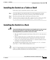
...: • This unit should be attached to a 19-, 23-, or 24-inch rack. The following guidelines are similar on brackets for two-rack-unit modular switches. Note Figure 2-1 shows brackets for one-rack-unit switches. 78-6461-04 Catalyst 2900 Series XL Hardware Installation Guide 2-9 Place the switch on page 2-24. Attach the four rubber...
...: • This unit should be attached to a 19-, 23-, or 24-inch rack. The following guidelines are similar on brackets for two-rack-unit modular switches. Note Figure 2-1 shows brackets for one-rack-unit switches. 78-6461-04 Catalyst 2900 Series XL Hardware Installation Guide 2-9 Place the switch on page 2-24. Attach the four rubber...

Hardware Installation Guide
Page 54
...instructions described in a 19-, 23- Installing the Switch in a Rack Chapter 2 Installation Figure 2-1 Mounting Bracket Points for Catalyst 2912 XL, 2924C XL, 2924 XL, 2912MF XL, 2924M XL, and 2924M XL DC Switches 19" rack mount point 24" rack 23" rack mount point mount point 47307 19" rack mount point 24..." rack 23" rack mount point mount point Figure 2-2 Mounting Brackets Points for Catalyst 2912 LRE XL and 2924 LRE XL Switches 19" rack mount point 24" rack...
...instructions described in a 19-, 23- Installing the Switch in a Rack Chapter 2 Installation Figure 2-1 Mounting Bracket Points for Catalyst 2912 XL, 2924C XL, 2924 XL, 2912MF XL, 2924M XL, and 2924M XL DC Switches 19" rack mount point 24" rack 23" rack mount point mount point 47307 19" rack mount point 24..." rack 23" rack mount point mount point Figure 2-2 Mounting Brackets Points for Catalyst 2912 LRE XL and 2924 LRE XL Switches 19" rack mount point 24" rack...

Hardware Installation Guide
Page 55
... the Optional Cable Guide" section on whether you use depend on page 2-19 Removing Screws from the Switch Catalyst 2900 SERIES XL Fixed-port Catalyst 2900 series XL Catalyst 2900 SERIES XL 22X 23X 24X Modular Catalyst 2900 series XL 47292 Attaching the Brackets to a Catalyst 2912 XL, 2924C XL, 2924 XL, 2912MF XL, 2924M XL, or...
... the Optional Cable Guide" section on whether you use depend on page 2-19 Removing Screws from the Switch Catalyst 2900 SERIES XL Fixed-port Catalyst 2900 series XL Catalyst 2900 SERIES XL 22X 23X 24X Modular Catalyst 2900 series XL 47292 Attaching the Brackets to a Catalyst 2912 XL, 2924C XL, 2924 XL, 2912MF XL, 2924M XL, or...
Hardware Installation Guide
Page 56
... to attach the long side of the bracket to one side of the switch. Figure 2-4 Attaching Brackets on Catalyst 2912 XL, 2924C XL, and 2924 XL Fixed-Port Switches (Front-Panel Forward) Phillips flat-head screws Phillips truss-head screws 19" configuration MODE 1X 2X 3X 4X 5X 6X 7X 47738 23" and ...24" configuration MODE 1X 2X 3X 4X 5X 6X 7X 2-12 Catalyst 2900 Series XL Hardware Installation Guide 78-6461...
... to attach the long side of the bracket to one side of the switch. Figure 2-4 Attaching Brackets on Catalyst 2912 XL, 2924C XL, and 2924 XL Fixed-Port Switches (Front-Panel Forward) Phillips flat-head screws Phillips truss-head screws 19" configuration MODE 1X 2X 3X 4X 5X 6X 7X 47738 23" and ...24" configuration MODE 1X 2X 3X 4X 5X 6X 7X 2-12 Catalyst 2900 Series XL Hardware Installation Guide 78-6461...

Hardware Installation Guide
Page 57
Chapter 2 Installation Installing the Switch in a Rack Figure 2-5 Attaching Brackets on Catalyst 2912MF XL, 2924M XL, and 2924M XL DC Modular Switches (Front-Panel Forward) Phillips flat-head screws 19" configuration Phillips truss-head screws 12 MODE 1X 2X 3X 4X 5X 6X 7X 23" and 24" configuration 12 MODE 1X 2X 3X 4X 5X 6X 7X 47297 78-6461-04 Catalyst 2900 Series XL Hardware Installation Guide 2-13
Chapter 2 Installation Installing the Switch in a Rack Figure 2-5 Attaching Brackets on Catalyst 2912MF XL, 2924M XL, and 2924M XL DC Modular Switches (Front-Panel Forward) Phillips flat-head screws 19" configuration Phillips truss-head screws 12 MODE 1X 2X 3X 4X 5X 6X 7X 23" and 24" configuration 12 MODE 1X 2X 3X 4X 5X 6X 7X 47297 78-6461-04 Catalyst 2900 Series XL Hardware Installation Guide 2-13

Hardware Installation Guide
Page 58
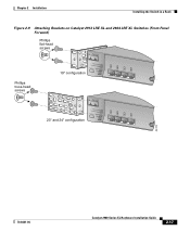
Installing the Switch in a Rack Chapter 2 Installation Figure 2-6 Attaching Brackets on Catalyst 2912 XL, 2924C XL, and 2924 XL Fixed-Port Switches (Rear-Panel Forward) 19" configuration Phillips flat-head screws 23" and 24" configuration Phillips truss-head screws 47298 2-14 Catalyst 2900 Series XL Hardware Installation Guide 78-6461-04
Installing the Switch in a Rack Chapter 2 Installation Figure 2-6 Attaching Brackets on Catalyst 2912 XL, 2924C XL, and 2924 XL Fixed-Port Switches (Rear-Panel Forward) 19" configuration Phillips flat-head screws 23" and 24" configuration Phillips truss-head screws 47298 2-14 Catalyst 2900 Series XL Hardware Installation Guide 78-6461-04

Hardware Installation Guide
Page 59
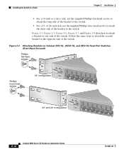
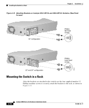
Chapter 2 Installation Installing the Switch in a Rack Figure 2-7 Attaching Brackets on Catalyst 2912MF XL, 2924M XL, and 2924M XL DC Modular Switches (Rear-Panel Forward) DC INPUT 21.000A-/11R2.0A0AT/2IN050G0--26400HVZ~ 19" configuration Phillips flat-head screws DC INPUT 21.00A0-/11R2.0A0AT/2IN050G0--26400HVZ~ Phillips truss-head screws... Brackets for Telco Racks 47299 DC INPUT 21.00A0-/11R2.0A0AT/2IN050G0--26400HVZ~ Phillips flat-head screws 71236 Note Only the Catalyst 2912MF XL, Catalyst 2924M XL, and Catalyst 2924M XL DC switches can be mounted in telco racks. 78-6461-04...
Chapter 2 Installation Installing the Switch in a Rack Figure 2-7 Attaching Brackets on Catalyst 2912MF XL, 2924M XL, and 2924M XL DC Modular Switches (Rear-Panel Forward) DC INPUT 21.000A-/11R2.0A0AT/2IN050G0--26400HVZ~ 19" configuration Phillips flat-head screws DC INPUT 21.00A0-/11R2.0A0AT/2IN050G0--26400HVZ~ Phillips truss-head screws... Brackets for Telco Racks 47299 DC INPUT 21.00A0-/11R2.0A0AT/2IN050G0--26400HVZ~ Phillips flat-head screws 71236 Note Only the Catalyst 2912MF XL, Catalyst 2924M XL, and Catalyst 2924M XL DC switches can be mounted in telco racks. 78-6461-04...
Hardware Installation Guide
Page 60
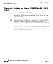
...install an LRE switch in a 23- Figure 2-3, Figure 2-5, Figure 2-6, Figure 2-7, and Figure 2-8 show how to attach a bracket to the opposite side of the bracket to a Catalyst 2912 LRE XL or 2924 LRE XL Switch A Catalyst 2912 LRE XL or 2924 LRE XL switch can only be rack-mounted in a 19-inch rack.... The mounting brackets shipped with a Catalyst 2900 LRE XL switch cannot support the switch in a 23or 24-inch rack. Follow the...
...install an LRE switch in a 23- Figure 2-3, Figure 2-5, Figure 2-6, Figure 2-7, and Figure 2-8 show how to attach a bracket to the opposite side of the bracket to a Catalyst 2912 LRE XL or 2924 LRE XL Switch A Catalyst 2912 LRE XL or 2924 LRE XL switch can only be rack-mounted in a 19-inch rack.... The mounting brackets shipped with a Catalyst 2900 LRE XL switch cannot support the switch in a 23or 24-inch rack. Follow the...
Hardware Installation Guide
Page 61
Chapter 2 Installation Installing the Switch in a Rack Figure 2-9 Attaching Brackets on Catalyst 2912 LRE XL and 2924 LRE XL Switches (Front-Panel Forward) Phillips flat-head screws Phillips truss-head screws 19" configuration INPUT OUTPUT PWR PWR RESET TEMP FAN 9X 10X 11X 12X 23" and 24" configuration INPUT OUTPUT PWR PWR RESET TEMP FAN 9X 10X 11X 12X 54728 78-6461-04 Catalyst 2900 Series XL Hardware Installation Guide 2-17
Chapter 2 Installation Installing the Switch in a Rack Figure 2-9 Attaching Brackets on Catalyst 2912 LRE XL and 2924 LRE XL Switches (Front-Panel Forward) Phillips flat-head screws Phillips truss-head screws 19" configuration INPUT OUTPUT PWR PWR RESET TEMP FAN 9X 10X 11X 12X 23" and 24" configuration INPUT OUTPUT PWR PWR RESET TEMP FAN 9X 10X 11X 12X 54728 78-6461-04 Catalyst 2900 Series XL Hardware Installation Guide 2-17
Hardware Installation Guide
Page 62
Installing the Switch in a Rack Chapter 2 Installation Figure 2-10 Attaching Brackets on Catalyst 2912 LRE XL and 2924 LRE XL Switches (Rear-Panel Forward 19" configuration Phillips flat-head screws 54824 Phillips truss-head screws 23" and 24" configuration Mounting the Switch in a Rack After the brackets are attached to the switch, use the four supplied number-12 Phillips machine screws to securely attach the brackets to the rack, as shown in Figure 2-11. 2-18 Catalyst 2900 Series XL Hardware Installation Guide 78-6461-04
Installing the Switch in a Rack Chapter 2 Installation Figure 2-10 Attaching Brackets on Catalyst 2912 LRE XL and 2924 LRE XL Switches (Rear-Panel Forward 19" configuration Phillips flat-head screws 54824 Phillips truss-head screws 23" and 24" configuration Mounting the Switch in a Rack After the brackets are attached to the switch, use the four supplied number-12 Phillips machine screws to securely attach the brackets to the rack, as shown in Figure 2-11. 2-18 Catalyst 2900 Series XL Hardware Installation Guide 78-6461-04
Hardware Installation Guide
Page 63
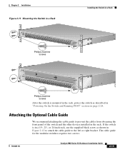
... Phillips machine screws 47301 12 MODE 1X 2X 3X Catalyst 2900 SERIES XL 4X 5X 6X 7X 8X 9X 100BaseFX 10X 11X 12X 13X 14X 15X 16X 17X 18X 19X 20X 21X 22X 23X 24X Phillips machine screws After the switch is in a 19-, 23-, or 24-inch rack, use the supplied black... screw as described in the rack. Attaching the Optional Cable Guide We recommend attaching the cable guide to the left or right bracket. The cable guide for the modular switches requires two screws. 78-6461-04 Catalyst 2900 Series...
... Phillips machine screws 47301 12 MODE 1X 2X 3X Catalyst 2900 SERIES XL 4X 5X 6X 7X 8X 9X 100BaseFX 10X 11X 12X 13X 14X 15X 16X 17X 18X 19X 20X 21X 22X 23X 24X Phillips machine screws After the switch is in a 19-, 23-, or 24-inch rack, use the supplied black... screw as described in the rack. Attaching the Optional Cable Guide We recommend attaching the cable guide to the left or right bracket. The cable guide for the modular switches requires two screws. 78-6461-04 Catalyst 2900 Series...
Hardware Installation Guide
Page 71
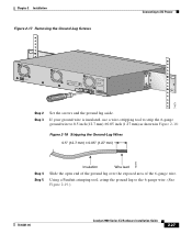
Chapter 2 Installation Figure 2-17 Removing the Ground-Lug Screws Connecting to the 6-gauge wire. (See Figure 2-19.) 78-6461-04 Catalyst 2900 Series XL Hardware Installation Guide 2-27 Using a Panduit crimping tool, crimp the ground lug to DC Power CONSOLE BERFEOFREERPOCTOWONEMNRAENCUTAINL G DC INPUT ICNUPRURTE: 3N6T:- 72 4-...
Chapter 2 Installation Figure 2-17 Removing the Ground-Lug Screws Connecting to the 6-gauge wire. (See Figure 2-19.) 78-6461-04 Catalyst 2900 Series XL Hardware Installation Guide 2-27 Using a Panduit crimping tool, crimp the ground lug to DC Power CONSOLE BERFEOFREERPOCTOWONEMNRAENCUTAINL G DC INPUT ICNUPRURTE: 3N6T:- 72 4-...

Hardware Installation Guide
Page 72
Connecting to DC Power Figure 2-19 Crimping the Ground Lug Chapter 2 Installation 60529 Step 6 Step 7 Use the two number-10-16 screws to attach the ground lug and wire assembly to 15 1bf-in. (or 240 ounce-force inches [240 ozf-in.]). (See Figure 2-20.) 2-28 Catalyst 2900 Series XL Hardware Installation Guide 78-6461-04 Using a ratcheting torque screwdriver, torque each ground-lug screw to the rear panel of the switch.
Connecting to DC Power Figure 2-19 Crimping the Ground Lug Chapter 2 Installation 60529 Step 6 Step 7 Use the two number-10-16 screws to attach the ground lug and wire assembly to 15 1bf-in. (or 240 ounce-force inches [240 ozf-in.]). (See Figure 2-20.) 2-28 Catalyst 2900 Series XL Hardware Installation Guide 78-6461-04 Using a ratcheting torque screwdriver, torque each ground-lug screw to the rear panel of the switch.

Hardware Installation Guide
Page 101
... Fiber-Port Power Levels 1.73 x 17.5 x 9.79 in . (4.4 x 44.5 x 24.8 cm) 1300 nm1 -14 dBm2 -19 to -14 dBm -19 to 60 Hz +5V @9A, +12V @0.5A Power consumption 70W (maximum) Physical Dimensions 239 Btus per hour 7 lb (3.2 kg) ...1.73 x 17.5 x 9.79 in . (4.4 x 44.5 x 24.8 cm) Optical transmitter - receiver Optical power transmitter - Appendix A Technical Specifications Table A-2 Technical Specifications for the Catalyst 2924 XL and Catalyst 2924C XL Switches Catalyst...
... Fiber-Port Power Levels 1.73 x 17.5 x 9.79 in . (4.4 x 44.5 x 24.8 cm) 1300 nm1 -14 dBm2 -19 to -14 dBm -19 to 60 Hz +5V @9A, +12V @0.5A Power consumption 70W (maximum) Physical Dimensions 239 Btus per hour 7 lb (3.2 kg) ...1.73 x 17.5 x 9.79 in . (4.4 x 44.5 x 24.8 cm) Optical transmitter - receiver Optical power transmitter - Appendix A Technical Specifications Table A-2 Technical Specifications for the Catalyst 2924 XL and Catalyst 2924C XL Switches Catalyst...

Hardware Installation Guide
Page 109
Circuits 14, tip/ring 15, tip/ring 16, tip/ring 17, tip/ring 18, tip/ring 19, tip/ring 20, tip/ring 21, tip/ring 22, tip/ring 23, tip/ring 24,...14, 39 2, tip/ring 15, 40 3, tip/ring 16, 41 4, tip/ring 17, 42 5, tip/ring 18, 43 6, tip/ring 19, 44 7, tip/ring 20, 45 8, tip/ring 21, 46 9, tip/ring 22, 47 10, tip/ring 23, 48 11, tip/ring ... - The supplied RJ-45-to-RJ-45 rollover cable and adapters connect the console port of the switch to 12 are valid. On a Catalyst 2912 LRE XL switch, only circuits 1 to a console PC or terminal. Note Table B-1 shows the pinouts for the console...
Circuits 14, tip/ring 15, tip/ring 16, tip/ring 17, tip/ring 18, tip/ring 19, tip/ring 20, tip/ring 21, tip/ring 22, tip/ring 23, tip/ring 24,...14, 39 2, tip/ring 15, 40 3, tip/ring 16, 41 4, tip/ring 17, 42 5, tip/ring 18, 43 6, tip/ring 19, 44 7, tip/ring 20, 45 8, tip/ring 21, 46 9, tip/ring 22, 47 10, tip/ring 23, 48 11, tip/ring ... - The supplied RJ-45-to-RJ-45 rollover cable and adapters connect the console port of the switch to 12 are valid. On a Catalyst 2912 LRE XL switch, only circuits 1 to a console PC or terminal. Note Table B-1 shows the pinouts for the console...