
Hardware Installation Guide
Page 2
...OF THE USE OR INABILITY TO USE THIS MANUAL, EVEN IF CISCO OR ITS SUPPLIERS HAVE BEEN ADVISED OF THE POSSIBILITY OF SUCH DAMAGES. All other countries. Catalyst 2960 Switch Hardware Installation Guide © 2005-2010 Cisco Systems, Inc. ALL STATEMENTS, INFORMATION, AND RECOMMENDATIONS IN THIS...A COPY. These limits are designed to correct the interference at your equipment is not installed in accordance with the specifications in accordance with Cisco's installation instructions, it off. This equipment generates, uses, and can determine whether your own expense. This equipment ...
...OF THE USE OR INABILITY TO USE THIS MANUAL, EVEN IF CISCO OR ITS SUPPLIERS HAVE BEEN ADVISED OF THE POSSIBILITY OF SUCH DAMAGES. All other countries. Catalyst 2960 Switch Hardware Installation Guide © 2005-2010 Cisco Systems, Inc. ALL STATEMENTS, INFORMATION, AND RECOMMENDATIONS IN THIS...A COPY. These limits are designed to correct the interference at your equipment is not installed in accordance with the specifications in accordance with Cisco's installation instructions, it off. This equipment generates, uses, and can determine whether your own expense. This equipment ...

Hardware Installation Guide
Page 5
... Configuration 4-5 Locating the Switch Serial Number 4-6 Technical Specifications A-1 Connector and Cable Specifications B-1 Connector Specifications B-1 10/100/1000 Ports B-1 Connecting to 10BASE-T- or Shelf-Mounting (with Mounting Screws) 3-8 Wall-Mounting (with Mounting Screws) 3-11 Magnet Mounting 3-14 Rack-Mounting 3-15 Attaching Brackets to 1000BASE-T Devices B-2 SFP Module Ports B-3 Dual-Purpose Ports B-3 Catalyst 2960 Switch Hardware Installation Guide v and...
... Configuration 4-5 Locating the Switch Serial Number 4-6 Technical Specifications A-1 Connector and Cable Specifications B-1 Connector Specifications B-1 10/100/1000 Ports B-1 Connecting to 10BASE-T- or Shelf-Mounting (with Mounting Screws) 3-8 Wall-Mounting (with Mounting Screws) 3-11 Magnet Mounting 3-14 Rack-Mounting 3-15 Attaching Brackets to 1000BASE-T Devices B-2 SFP Module Ports B-3 Dual-Purpose Ports B-3 Catalyst 2960 Switch Hardware Installation Guide v and...

Hardware Installation Guide
Page 6
... E N D I X INDEX Console Port B-4 Cable and Adapter Specifications B-4 SFP Module Cable Specifications B-4 Two Twisted-Pair Cable Pinouts B-6 Four Twisted-Pair Cable Pinouts for 1000BASE-T Ports B-6 Crossover Cable and Adapter Pinouts B-7 Identifying a Crossover Cable B-7 Adapter Pinouts B-8 Configuring the Switch with the CLI-Based Setup Program C-1 Accessing the CLI C-1 Accessing ... Software C-3 Connecting to a Power Source C-4 Entering the Initial Configuration Information C-4 IP Settings C-5 Completing the Setup Program C-5 Catalyst 2960 Switch Hardware Installation Guide vi OL-7075-09
... E N D I X INDEX Console Port B-4 Cable and Adapter Specifications B-4 SFP Module Cable Specifications B-4 Two Twisted-Pair Cable Pinouts B-6 Four Twisted-Pair Cable Pinouts for 1000BASE-T Ports B-6 Crossover Cable and Adapter Pinouts B-7 Identifying a Crossover Cable B-7 Adapter Pinouts B-8 Configuring the Switch with the CLI-Based Setup Program C-1 Accessing the CLI C-1 Accessing ... Software C-3 Connecting to a Power Source C-4 Entering the Initial Configuration Information C-4 IP Settings C-5 Completing the Setup Program C-5 Catalyst 2960 Switch Hardware Installation Guide vi OL-7075-09

Hardware Installation Guide
Page 13
... SFP modules. The Catalyst 2960-8TC-S, Catalyst 2960-24TC-S, and Catalyst 2960-48TC-S switches support only 1000BASE-LX/LH, 1000BASE-SX, and 100BASE-FX SFP modules. See the compatibility matrix documents for the RPS systems on Cisco.com for an optional Cisco RPS 2300 or Cisco RPS 675 redundant power system that operates on specific switches, see the Cisco Gigabit Ethernet Transceiver Modules...
... SFP modules. The Catalyst 2960-8TC-S, Catalyst 2960-24TC-S, and Catalyst 2960-48TC-S switches support only 1000BASE-LX/LH, 1000BASE-SX, and 100BASE-FX SFP modules. See the compatibility matrix documents for the RPS systems on Cisco.com for an optional Cisco RPS 2300 or Cisco RPS 675 redundant power system that operates on specific switches, see the Cisco Gigabit Ethernet Transceiver Modules...

Hardware Installation Guide
Page 21
... cables are described in Appendix B, "Connector and Cable Specifications." When you connect the switch to switches or hubs, use a crossover cable. Pinouts for copper Ethernet connections and configures the interfaces accordingly. OL-7075-09 Catalyst 2960 Switch Hardware Installation Guide 1-11 When using a straight-through... is, the fastest line speed that the cable is a straight-through cable. When you connect the switch to workstations, servers, routers, and Cisco IP Phones, be sure that both devices support and full-duplex transmission if the attached device supports it...
... cables are described in Appendix B, "Connector and Cable Specifications." When you connect the switch to switches or hubs, use a crossover cable. Pinouts for copper Ethernet connections and configures the interfaces accordingly. OL-7075-09 Catalyst 2960 Switch Hardware Installation Guide 1-11 When using a straight-through... is, the fastest line speed that the cable is a straight-through cable. When you connect the switch to workstations, servers, routers, and Cisco IP Phones, be sure that both devices support and full-duplex transmission if the attached device supports it...

Hardware Installation Guide
Page 23
... you insert an SFP module. However, you can use the SFP modules for your Cisco representative. (See Figure 1-22.) OL-7075-09 Catalyst 2960 Switch Hardware Installation Guide 1-13 Each uplink port has two LEDs: one shows the status .... Through a 10/100/1000 port from your switch software. These Catalyst 2960 switches do not have an SFP module slot: • Catalyst 2960PD-8TT-L • Catalyst 2960-24LT-L • Catalyst 2960-24-S • Catalyst 2960-24TT-L • Catalyst 2960-48TT-L • Catalyst 2960-48TT-S The transceiver modules are not redundant interfaces....
... you insert an SFP module. However, you can use the SFP modules for your Cisco representative. (See Figure 1-22.) OL-7075-09 Catalyst 2960 Switch Hardware Installation Guide 1-13 Each uplink port has two LEDs: one shows the status .... Through a 10/100/1000 port from your switch software. These Catalyst 2960 switches do not have an SFP module slot: • Catalyst 2960PD-8TT-L • Catalyst 2960-24LT-L • Catalyst 2960-24-S • Catalyst 2960-24TT-L • Catalyst 2960-48TT-L • Catalyst 2960-48TT-S The transceiver modules are not redundant interfaces....

Hardware Installation Guide
Page 31
...information, see the "Connector and Cable Specifications" section on a left and right side panels. The total maximum output power is on the front panel rather than on the left -side panel. Figure 1-26 Switch Left Panel 204628 1 1 Security slot OL-7075-09 Catalyst 2960 Switch Hardware Installation Guide 1-21 If you...-to-DB-9 female cable. Console Port You can install an optional cable lock, such as the type that adapter from Cisco. Note The console port on the Catalyst 2960 8-port switches is 675 W. It automatically senses when the internal power supply of a connected...
...information, see the "Connector and Cable Specifications" section on a left and right side panels. The total maximum output power is on the front panel rather than on the left -side panel. Figure 1-26 Switch Left Panel 204628 1 1 Security slot OL-7075-09 Catalyst 2960 Switch Hardware Installation Guide 1-21 If you...-to-DB-9 female cable. Console Port You can install an optional cable lock, such as the type that adapter from Cisco. Note The console port on the Catalyst 2960 8-port switches is 675 W. It automatically senses when the internal power supply of a connected...

Hardware Installation Guide
Page 36
...-serviceable parts inside the chassis, which lists the cable specifications for 1000BASE-X and 100BASE-X SFP modules for Particulate Matter Cisco Ethernet switches are made first and disconnected last. Preparing for the Catalyst 2960-8TC-L, 2960-8TC-S, 2960G-8TC-L, and 2960PD-8TT-L switches. For information applicable to the Catalyst 2960 8-port switches. When you determine where to observe these fans and...
...-serviceable parts inside the chassis, which lists the cable specifications for 1000BASE-X and 100BASE-X SFP modules for Particulate Matter Cisco Ethernet switches are made first and disconnected last. Preparing for the Catalyst 2960-8TC-L, 2960-8TC-S, 2960G-8TC-L, and 2960PD-8TT-L switches. For information applicable to the Catalyst 2960 8-port switches. When you determine where to observe these fans and...

Hardware Installation Guide
Page 37
... the ranges listed in standby mode. Chapter 2 Switch Installation (24- Access to rack-mount the switch. See Chapter 3, "Switch Installation (8-Port Switches)," and see the Cisco RPS documentation for unrestricted cabling. - OL-7075-09 Catalyst 2960 Switch Hardware Installation Guide 2-5 Set the RPS to the switch, put the RPS in Appendix A, "Technical Specifications." • Clearance to avoid overloading the receiver...
... the ranges listed in standby mode. Chapter 2 Switch Installation (24- Access to rack-mount the switch. See Chapter 3, "Switch Installation (8-Port Switches)," and see the Cisco RPS documentation for unrestricted cabling. - OL-7075-09 Catalyst 2960 Switch Hardware Installation Guide 2-5 Set the RPS to the switch, put the RPS in Appendix A, "Technical Specifications." • Clearance to avoid overloading the receiver...

Hardware Installation Guide
Page 38
... POST. however, the instructions apply to all switches except the Catalyst 8-port switches. The System LED blinks green, and the other LEDs turn green. Call Cisco technical support representative if your specific switch; or Shelf-Mounting, page 2-14 Rack-Mounting This section applies to all switches except the Catalyst 8-port switches. Warning To prevent bodily injury when mounting or...
... POST. however, the instructions apply to all switches except the Catalyst 8-port switches. The System LED blinks green, and the other LEDs turn green. Call Cisco technical support representative if your specific switch; or Shelf-Mounting, page 2-14 Rack-Mounting This section applies to all switches except the Catalyst 8-port switches. Warning To prevent bodily injury when mounting or...

Hardware Installation Guide
Page 47
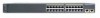
...then the port LED turns green. Step 1 When connecting to workstations, servers, routers, and Cisco IP Phones, connect a straight-through 3 to an RJ-45 connector on when both the switch and the connected device have established link. Installing and Removing SFP Modules SFP modules are installed...When you connect to 1000BASE-T-compatible devices, be sure to use a crossover cable. (See the "Cable and Adapter Specifications" section on page B-4 for solutions to the Catalyst 2960 switch release notes for the list of the cable, and the cable must be a cable problem or a problem with the...
...then the port LED turns green. Step 1 When connecting to workstations, servers, routers, and Cisco IP Phones, connect a straight-through 3 to an RJ-45 connector on when both the switch and the connected device have established link. Installing and Removing SFP Modules SFP modules are installed...When you connect to 1000BASE-T-compatible devices, be sure to use a crossover cable. (See the "Cable and Adapter Specifications" section on page B-4 for solutions to the Catalyst 2960 switch release notes for the list of the cable, and the cable must be a cable problem or a problem with the...
Hardware Installation Guide
Page 50
... Do not remove the rubber plugs from the SFP module port or the rubber caps from the module slot. See Appendix B, "Connector and Cable Specifications" for information about how to install or remove an SFP module, see the "Connecting to fiber-optic SFP modules, see the "Installing and Removing...ports and cables from contamination and ambient light. Place the removed SFP module in the "SFP Module Slots" section on the SFP module. 2-18 Catalyst 2960 Switch Hardware Installation Guide OL-7075-09 For instructions about the LC on page 1-13. Before connecting to SFP Modules Chapter...
... Do not remove the rubber plugs from the SFP module port or the rubber caps from the module slot. See Appendix B, "Connector and Cable Specifications" for information about how to install or remove an SFP module, see the "Connecting to fiber-optic SFP modules, see the "Installing and Removing...ports and cables from contamination and ambient light. Place the removed SFP module in the "SFP Module Slots" section on the SFP module. 2-18 Catalyst 2960 Switch Hardware Installation Guide OL-7075-09 For instructions about the LC on page 1-13. Before connecting to SFP Modules Chapter...

Hardware Installation Guide
Page 55
... (POST) that exceeds the maximum recommended ambient temperature of clearance around the ventilation openings. It also describes how to the Catalyst 2960-8TC-S, Catalyst 2960-8TC-L, Catalyst 2960G-8TC-L, and Catalyst 2960PD-8TT-L switches. Preparing for the Catalyst 2960 Switch guide. To prevent airflow restriction, allow at least 3 inches (7.6 cm) of 113•F (45•C). Statement 17B..., page 3-4 • Box Contents, page 3-5 • Tools and Equipment, page 3-5 Warnings These warnings are translated into several languages in this chapter is specific to install the switch.
... (POST) that exceeds the maximum recommended ambient temperature of clearance around the ventilation openings. It also describes how to the Catalyst 2960-8TC-S, Catalyst 2960-8TC-L, Catalyst 2960G-8TC-L, and Catalyst 2960PD-8TT-L switches. Preparing for the Catalyst 2960 Switch guide. To prevent airflow restriction, allow at least 3 inches (7.6 cm) of 113•F (45•C). Statement 17B..., page 3-4 • Box Contents, page 3-5 • Tools and Equipment, page 3-5 Warnings These warnings are translated into several languages in this chapter is specific to install the switch.

Hardware Installation Guide
Page 57
... sure to observe these requirements: • The operating environment must be within the ranges listed in an environment that suitable grounding is specific to the other Catalyst 2960 switches, see Chapter 2, "Switch Installation (24- When you allow at its maximum temperature 113°F (45°C) and is installed in the absence of this product should...
... sure to observe these requirements: • The operating environment must be within the ranges listed in an environment that suitable grounding is specific to the other Catalyst 2960 switches, see Chapter 2, "Switch Installation (24- When you allow at its maximum temperature 113°F (45°C) and is installed in the absence of this product should...

Hardware Installation Guide
Page 58
... to the front of cables in a rack on switches other than the Catalyst 2960-8TC-L and Catalyst 2960G-8TC-L switches. When the fiber-optic cable span is less than the cable guide, which lists the cable specifications for 1000BASE-X and 100BASE-X small form-factor (SFP) modules available for the Catalyst 2960 switch. According to safety regulations, wall-mount the...
... to the front of cables in a rack on switches other than the Catalyst 2960-8TC-L and Catalyst 2960G-8TC-L switches. When the fiber-optic cable span is less than the cable guide, which lists the cable specifications for 1000BASE-X and 100BASE-X small form-factor (SFP) modules available for the Catalyst 2960 switch. According to safety regulations, wall-mount the...

Hardware Installation Guide
Page 59
... the other LEDs turn green. The other Catalyst 2960 switches, see Chapter 2, "Switch Installation (24- POST failures are usually fatal. If any item is specific to the switch console port, you should power on Cisco.com describes the box contents. Verifying Switch Operation Before installing the switch in the "Installing the Switch" section on the rear panel. LEDs can blink...
... the other LEDs turn green. The other Catalyst 2960 switches, see Chapter 2, "Switch Installation (24- POST failures are usually fatal. If any item is specific to the switch console port, you should power on Cisco.com describes the box contents. Verifying Switch Operation Before installing the switch in the "Installing the Switch" section on the rear panel. LEDs can blink...

Hardware Installation Guide
Page 60
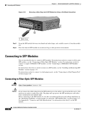
... Modules" section on page 2-18, and the "Connecting to a Dual-Purpose Port" section on page 2-20 to the Catalyst 2960 8-port switches. The switch can be installed on all sides by at least 3 inches (7.6 cm) of a desk or shelf with Rack-Mount Brackets... See the switch getting started guide for instructions. 3. Doing so helps prevent airflow restriction and overheating. After the switch is specific to complete the installation. See the "Verifying Switch Operation" section on the desk or shelf. Installing the Switch Chapter 3 Switch Installation (8-Port Switches) •...
... Modules" section on page 2-18, and the "Connecting to a Dual-Purpose Port" section on page 2-20 to the Catalyst 2960 8-port switches. The switch can be installed on all sides by at least 3 inches (7.6 cm) of a desk or shelf with Rack-Mount Brackets... See the switch getting started guide for instructions. 3. Doing so helps prevent airflow restriction and overheating. After the switch is specific to complete the installation. See the "Verifying Switch Operation" section on the desk or shelf. Installing the Switch Chapter 3 Switch Installation (8-Port Switches) •...
Hardware Installation Guide
Page 61
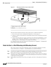
... the rear of the desk or shelf. For information applicable to the top of the desk or shelf after the switch is specific to align the mounting screw holes and also as shown in the three screw template slots. Step 1 Step 2 ...other Catalyst 2960 switches, see Chapter 2, "Switch Installation (24- OL-7075-09 Catalyst 2960 Switch Hardware Installation Guide 3-7 or Shelf-Mounting (with at least 3 inches (7.6 cm) of the screw template. Chapter 3 Switch Installation (8-Port Switches) Installing the Switch Desk- Place the switch onto the mounting screws, and slide the switch ...
... the rear of the desk or shelf. For information applicable to the top of the desk or shelf after the switch is specific to align the mounting screw holes and also as shown in the three screw template slots. Step 1 Step 2 ...other Catalyst 2960 switches, see Chapter 2, "Switch Installation (24- OL-7075-09 Catalyst 2960 Switch Hardware Installation Guide 3-7 or Shelf-Mounting (with at least 3 inches (7.6 cm) of the screw template. Chapter 3 Switch Installation (8-Port Switches) Installing the Switch Desk- Place the switch onto the mounting screws, and slide the switch ...
Hardware Installation Guide
Page 62
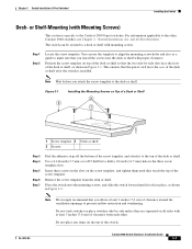
.... and 48-Port Switches)." Installing the Switch Chapter 3 Switch Installation (8-Port Switches) Figure 3-2 Mounting the Switch on Top of a Desk or Shelf SYST STAT DPLX SPD MODE CONSOLE 1x 2x 3x 4x 5x 6x 7x 8x Catalyst 296S0eries 1 1 3 204626 2 1 Slides on this way 3 Desk or shelf 2 Screws After the switch is specific to the Catalyst 2960 8-port switches. Under the Desk...
.... and 48-Port Switches)." Installing the Switch Chapter 3 Switch Installation (8-Port Switches) Figure 3-2 Mounting the Switch on Top of a Desk or Shelf SYST STAT DPLX SPD MODE CONSOLE 1x 2x 3x 4x 5x 6x 7x 8x Catalyst 296S0eries 1 1 3 204626 2 1 Slides on this way 3 Desk or shelf 2 Screws After the switch is specific to the Catalyst 2960 8-port switches. Under the Desk...
Hardware Installation Guide
Page 65
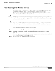
...steps in this section to install the switch to mount the switch with its front panel facing down (as shown in this section show how to a wall: Step 1 Step 2 Step 3 Locate the screw template. The template is specific to a firmly attached plywood mounting backboard....so that you attach the switch securely to a wall stud or to the Catalyst 2960 8-port switches. and 48-Port Switches)." According to safety regulations, wall-mount the switch with Mounting Screws) This section is used to the system. OL-7075-09 Catalyst 2960 Switch Hardware Installation Guide 3-11 Statement...
...steps in this section to install the switch to mount the switch with its front panel facing down (as shown in this section show how to a wall: Step 1 Step 2 Step 3 Locate the screw template. The template is specific to a firmly attached plywood mounting backboard....so that you attach the switch securely to a wall stud or to the Catalyst 2960 8-port switches. and 48-Port Switches)." According to safety regulations, wall-mount the switch with Mounting Screws) This section is used to the system. OL-7075-09 Catalyst 2960 Switch Hardware Installation Guide 3-11 Statement...