
Hardware Installation Guide
Page 3
... LEDs 1-14 System LED 1-15 RPS LED 1-16 Port LEDs and Modes 1-16 Dual-Purpose Port LEDs 1-18 Cable Guard for the Catalyst 2960 8-Port Switches 1-19 Rear Panel Description 1-19 Internal Power Supply 1-20 Cisco RPS 1-20 Cisco RPS 2300 1-20 Cisco RPS 675 1-21 Console Port 1-21 Security Slots 1-21 Management Options 1-22 Network Configurations 1-22...
... LEDs 1-14 System LED 1-15 RPS LED 1-16 Port LEDs and Modes 1-16 Dual-Purpose Port LEDs 1-18 Cable Guard for the Catalyst 2960 8-Port Switches 1-19 Rear Panel Description 1-19 Internal Power Supply 1-20 Cisco RPS 1-20 Cisco RPS 2300 1-20 Cisco RPS 675 1-21 Console Port 1-21 Security Slots 1-21 Management Options 1-22 Network Configurations 1-22...

Hardware Installation Guide
Page 13
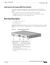
...; Catalyst 2960-48TC-S OL-7075-09 Catalyst 2960 Switch Hardware Installation Guide 1-3 The Catalyst 2960-8TC-S, Catalyst 2960-24TC-S, and Catalyst 2960-48TC-S switches support only 1000BASE-LX/LH, 1000BASE-SX, and 100BASE-FX SFP modules. Chapter 1 Product Overview Features These are supported on AC input and supplies backup DC power to the switch. See the compatibility matrix documents for the RPS systems on Cisco.com...
...; Catalyst 2960-48TC-S OL-7075-09 Catalyst 2960 Switch Hardware Installation Guide 1-3 The Catalyst 2960-8TC-S, Catalyst 2960-24TC-S, and Catalyst 2960-48TC-S switches support only 1000BASE-LX/LH, 1000BASE-SX, and 100BASE-FX SFP modules. Chapter 1 Product Overview Features These are supported on AC input and supplies backup DC power to the switch. See the compatibility matrix documents for the RPS systems on Cisco.com...

Hardware Installation Guide
Page 26
... LED is off or not properly connected. If it is providing power to the switch (redundancy has been allocated to this device). Contact Cisco Systems. The internal power supply in half-duplex mode. 2. This is in standby mode or in a fault condition. When installed in Catalyst 2960 switches, 1000BASE-T SFP modules can operate at 10, 100, or 1000...
... LED is off or not properly connected. If it is providing power to the switch (redundancy has been allocated to this device). Contact Cisco Systems. The internal power supply in half-duplex mode. 2. This is in standby mode or in a fault condition. When installed in Catalyst 2960 switches, 1000BASE-T SFP modules can operate at 10, 100, or 1000...
Hardware Installation Guide
Page 29
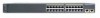
... a Catalyst 2960 rear panel). These Catalyst 2960 switches do not have an AC internal power supply. Figure 1-25 Catalyst 2960 Switch Rear Panel 137071 CONSOLE 1 2 3 4 1 RJ-45 console port1 2 Fan exhaust3 3 RPS connector 2 4 AC power connector4 1. To order a cable guard, contact your Cisco representative using these part numbers: • CBLGRD-C2960-8TC: Catalyst 2960-8TC-L, 2960-8TC-S, and 2960PD-8TT-L switches • CBLGRD-C2960G-8TC: Cisco Catalyst 2960G...
... a Catalyst 2960 rear panel). These Catalyst 2960 switches do not have an AC internal power supply. Figure 1-25 Catalyst 2960 Switch Rear Panel 137071 CONSOLE 1 2 3 4 1 RJ-45 console port1 2 Fan exhaust3 3 RPS connector 2 4 AC power connector4 1. To order a cable guard, contact your Cisco representative using these part numbers: • CBLGRD-C2960-8TC: Catalyst 2960-8TC-L, 2960-8TC-S, and 2960PD-8TT-L switches • CBLGRD-C2960G-8TC: Cisco Catalyst 2960G...
Hardware Installation Guide
Page 30
... switches at a time. Note These Catalyst 2960 switches support only the Cisco RPS 2300: Catalyst 2960-24PC-L, 2960-24LT-L, and 2960-48PST-L switches. Rear Panel Description Chapter 1 Product Overview Internal Power Supply All switches other than the Catalyst 2960PD-8TT-L are powered through the switch software: • Enable RPS active or standby mode for each connected switch • Configure switch priority for each Catalyst 2960 switch, see "Power Input Port (Catalyst 2960PD-8TT-L Switch...
... switches at a time. Note These Catalyst 2960 switches support only the Cisco RPS 2300: Catalyst 2960-24PC-L, 2960-24LT-L, and 2960-48PST-L switches. Rear Panel Description Chapter 1 Product Overview Internal Power Supply All switches other than the Catalyst 2960PD-8TT-L are powered through the switch software: • Enable RPS active or standby mode for each connected switch • Configure switch priority for each Catalyst 2960 switch, see "Power Input Port (Catalyst 2960PD-8TT-L Switch...

Hardware Installation Guide
Page 31
... slot OL-7075-09 Catalyst 2960 Switch Hardware Installation Guide 1-21 You can install an optional cable lock, such as the type that is a redundant power system that adapter from Cisco. Chapter 1 Product Overview Rear Panel Description • List the connected switches and the power-supply module sizes • Obtain reports when a switch is powered by means of the console...
... slot OL-7075-09 Catalyst 2960 Switch Hardware Installation Guide 1-21 You can install an optional cable lock, such as the type that is a redundant power system that adapter from Cisco. Chapter 1 Product Overview Rear Panel Description • List the connected switches and the power-supply module sizes • Obtain reports when a switch is powered by means of the console...
Hardware Installation Guide
Page 35
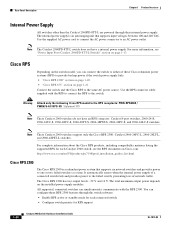
...take special precautions to all times, because it is available. Statement 1024 Warning This unit might have more than one power supply connection. Statement 1030 Warning Ultimate disposal of this product should be accessed only through an approved network termination unit with ... qualified personnel should be allowed to de-energize the unit. All connections must be grounded. Statement 1044 OL-7075-09 Catalyst 2960 Switch Hardware Installation Guide 2-3 Statement 1008 Warning This unit is provided with the heaviest component at all national laws and regulations....
...take special precautions to all times, because it is available. Statement 1024 Warning This unit might have more than one power supply connection. Statement 1030 Warning Ultimate disposal of this product should be accessed only through an approved network termination unit with ... qualified personnel should be allowed to de-energize the unit. All connections must be grounded. Statement 1044 OL-7075-09 Catalyst 2960 Switch Hardware Installation Guide 2-3 Statement 1008 Warning This unit is provided with the heaviest component at all national laws and regulations....

Hardware Installation Guide
Page 37
... (25 km), you connect the RPS to an AC power outlet. OL-7075-09 Catalyst 2960 Switch Hardware Installation Guide 2-5 If the switch is away from other end of electrical noise, such as radios, power lines, and fluorescent lighting fixtures. Tools and Equipment You .... • Temperature around it might need to supply a number-2 Phillips screwdriver to avoid overloading the receiver. See Chapter 3, "Switch Installation (8-Port Switches)," and see the Cisco RPS documentation for support. and 48-Port Switches) Verifying Switch Operation When you use shorter lengths of single-mode...
... (25 km), you connect the RPS to an AC power outlet. OL-7075-09 Catalyst 2960 Switch Hardware Installation Guide 2-5 If the switch is away from other end of electrical noise, such as radios, power lines, and fluorescent lighting fixtures. Tools and Equipment You .... • Temperature around it might need to supply a number-2 Phillips screwdriver to avoid overloading the receiver. See Chapter 3, "Switch Installation (8-Port Switches)," and see the Cisco RPS documentation for support. and 48-Port Switches) Verifying Switch Operation When you use shorter lengths of single-mode...
Hardware Installation Guide
Page 42
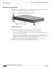
..." section on the switch. Figure 2-8 Mounting the Catalyst 2960 Switch in a Rack 204618 SYST RPS STAT DUPLX SPEED MODE 1 1 Phillips machine screws After the switch is mounted in Figure 2-8. Installing the Switch Chapter 2 Switch Installation (24- and 48-Port Switches) Mounting the Switch in a Rack After the brackets are attached to the switch, use the four supplied number-12 Phillips machine...
..." section on the switch. Figure 2-8 Mounting the Catalyst 2960 Switch in a Rack 204618 SYST RPS STAT DUPLX SPEED MODE 1 1 Phillips machine screws After the switch is mounted in Figure 2-8. Installing the Switch Chapter 2 Switch Installation (24- and 48-Port Switches) Mounting the Switch in a Rack After the brackets are attached to the switch, use the four supplied number-12 Phillips machine...
Hardware Installation Guide
Page 45
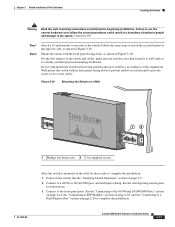
... Warning If a redundant power system (RPS) is attached securely to wall studs or to the switch, install an RPS connector cover on a Wall 11X 12X 11X 1X 12X 11X 1X 12X 1X 1X 11X 1X 12X MODE STASCPKEDEUDPSLTXAMTASRTPRSSYST 1 1 1 User-supplied screws 204621 OL-7075-09 Catalyst 2960 Switch Hardware Installation Guide 2-13 Chapter 2 Switch Installation (24- Statement...
... Warning If a redundant power system (RPS) is attached securely to wall studs or to the switch, install an RPS connector cover on a Wall 11X 12X 11X 1X 12X 11X 1X 12X 1X 1X 11X 1X 12X MODE STASCPKEDEUDPSLTXAMTASRTPRSSYST 1 1 1 User-supplied screws 204621 OL-7075-09 Catalyst 2960 Switch Hardware Installation Guide 2-13 Chapter 2 Switch Installation (24- Statement...

Hardware Installation Guide
Page 55
... 3-1 • Installation Guidelines, page 3-3 • Equipment That You Supply, page 3-4 • Box Contents, page 3-5 • Tools and Equipment, page 3-5 Warnings These warnings are translated into several languages in this order: • Preparing for the Catalyst 2960 Switch guide. For installation information applicable to interpret the power-on self-test (POST) that exceeds the maximum recommended...
... 3-1 • Installation Guidelines, page 3-3 • Equipment That You Supply, page 3-4 • Box Contents, page 3-5 • Tools and Equipment, page 3-5 Warnings These warnings are translated into several languages in this order: • Preparing for the Catalyst 2960 Switch guide. For installation information applicable to interpret the power-on self-test (POST) that exceeds the maximum recommended...

Hardware Installation Guide
Page 58
...as the type that might need this equipment to install the switch: • Number-2 Phillips screwdriver • Drill with a #27 drill bit (0.144-inch [3.7 mm]) You can easily read the front-panel indicators. - Equipment That You Supply This section is less than 15.43 miles (25 km), ...optional cable lock, such as radios, power lines, and fluorescent lighting fixtures. When you use to manage a large number of cables in the left and right side panels. When the fiber-optic cable span is specific to the other Catalyst 2960 switches, see Chapter 2, "Switch Installation (24- You need to ...
...as the type that might need this equipment to install the switch: • Number-2 Phillips screwdriver • Drill with a #27 drill bit (0.144-inch [3.7 mm]) You can easily read the front-panel indicators. - Equipment That You Supply This section is less than 15.43 miles (25 km), ...optional cable lock, such as radios, power lines, and fluorescent lighting fixtures. When you use to manage a large number of cables in the left and right side panels. When the fiber-optic cable span is specific to the other Catalyst 2960 switches, see Chapter 2, "Switch Installation (24- You need to ...

Hardware Installation Guide
Page 59
.... Chapter 3 Switch Installation (8-Port Switches) Verifying Switch Operation Installing the Catalyst 2960 8-port switches in a 19-inch rack requires an optional bracket kit that is specific to the Catalyst 2960 8-port switches. If you want to connect a terminal to ensure that the switch functions properly. You can blink during the test. See the "Power Input Port (Catalyst 2960PD-8TT-L Switch)" section on Cisco.com...
.... Chapter 3 Switch Installation (8-Port Switches) Verifying Switch Operation Installing the Catalyst 2960 8-port switches in a 19-inch rack requires an optional bracket kit that is specific to the Catalyst 2960 8-port switches. If you want to connect a terminal to ensure that the switch functions properly. You can blink during the test. See the "Power Input Port (Catalyst 2960PD-8TT-L Switch)" section on Cisco.com...
Hardware Installation Guide
Page 71
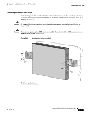
... 10/100 or 10/100/1000 port, and run Express Setup. Connect to safety regulations. OL-7075-09 Catalyst 2960 Switch Hardware Installation Guide 3-17 For the best support of the switch. See the "Connecting to the 10/100 and 10/100/1000 Ports" section on page 2-14, the "...damage to one side of the switch and cables, make sure the switch is mounted on a Wall 12 204634 1 Phillips flat-head screw 2 User-supplied screws After the switch is attached securely to wall studs or to complete the installation. Power on page 3-5. 2. See the switch getting started guide for instructions. ...
... 10/100 or 10/100/1000 port, and run Express Setup. Connect to safety regulations. OL-7075-09 Catalyst 2960 Switch Hardware Installation Guide 3-17 For the best support of the switch. See the "Connecting to the 10/100 and 10/100/1000 Ports" section on page 2-14, the "...damage to one side of the switch and cables, make sure the switch is mounted on a Wall 12 204634 1 Phillips flat-head screw 2 User-supplied screws After the switch is attached securely to wall studs or to complete the installation. Power on page 3-5. 2. See the switch getting started guide for instructions. ...
Hardware Installation Guide
Page 97
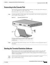
...terminal-emulation program and open a session if you can use the supplied RJ-45-to-DB-9 adapter cable. Follow these steps to connect the PC or terminal to the switch: Step 1 Using the supplied RJ-45-to-DB-9 adapter cable, insert the RJ-45 connector... in Figure C-1. OL-7075-09 Catalyst 2960 Switch Hardware Installation Guide C-3 Figure C-1 Connecting a Switch to a PC 1 CONSOLE 137088 3 2 1 Catalyst 2960 switch 3 RJ-45-to perform the initial configuration. To connect the switch console port to a PC, use the console port to -DB-9 adapter cable 2 Power cord Step 2 Attach the DB-9...
...terminal-emulation program and open a session if you can use the supplied RJ-45-to-DB-9 adapter cable. Follow these steps to connect the PC or terminal to the switch: Step 1 Using the supplied RJ-45-to-DB-9 adapter cable, insert the RJ-45 connector... in Figure C-1. OL-7075-09 Catalyst 2960 Switch Hardware Installation Guide C-3 Figure C-1 Connecting a Switch to a PC 1 CONSOLE 137088 3 2 1 Catalyst 2960 switch 3 RJ-45-to perform the initial configuration. To connect the switch console port to a PC, use the console port to -DB-9 adapter cable 2 Power cord Step 2 Attach the DB-9...

Hardware Installation Guide
Page 98
... information is powered up. Connecting to a Power Source Appendix C Configuring the Switch with your RPS. Call Cisco technical support representative if your switch, the PC or terminal displays the bootloader sequence. Note If you powered on your switch fails POST. Catalyst 2960 Switch Hardware Installation ...None (flow control) Connecting to a Power Source Follow these steps to connect to a power source: Step 1 Step 2 Connect one end of the supplied AC power cord to the power connector on self test (POST), a series of the power cable to display the setup program ...
... information is powered up. Connecting to a Power Source Appendix C Configuring the Switch with your RPS. Call Cisco technical support representative if your switch, the PC or terminal displays the bootloader sequence. Note If you powered on your switch fails POST. Catalyst 2960 Switch Hardware Installation ...None (flow control) Connecting to a Power Source Follow these steps to connect to a power source: Step 1 Step 2 Connect one end of the supplied AC power cord to the power connector on self test (POST), a series of the power cable to display the setup program ...

Hardware Installation Guide
Page 105
...power source C-4 mounting in a rack (8-port switches) 3-15 to 3-16 on desk or shelf 2-14, 3-6, 3-11 under a desk 3-8 using a magnet 3-14 site requirements 2-4, 3-3 starting the terminal emulation software C-3 See also procedures installation instructions warning 2-2, 3-2 installing SFP modules 2-16 to 2-17 internal power supply... 2-10, 3-16 N Network Assistant described 1-22 to configure switch 2-21, 3-18 network configuration examples 1-1 noise, electrical 2-5, 3-4 no user-serviceable parts warning 2-4 O overheating warning 2-2, 3-1 Catalyst 2960 Switch Hardware Installation Guide IN-3
...power source C-4 mounting in a rack (8-port switches) 3-15 to 3-16 on desk or shelf 2-14, 3-6, 3-11 under a desk 3-8 using a magnet 3-14 site requirements 2-4, 3-3 starting the terminal emulation software C-3 See also procedures installation instructions warning 2-2, 3-2 installing SFP modules 2-16 to 2-17 internal power supply... 2-10, 3-16 N Network Assistant described 1-22 to configure switch 2-21, 3-18 network configuration examples 1-1 noise, electrical 2-5, 3-4 no user-serviceable parts warning 2-4 O overheating warning 2-2, 3-1 Catalyst 2960 Switch Hardware Installation Guide IN-3
Hardware Installation Guide
Page 106
... ports 1-8 POST LEDs 2-6, 3-5, 4-2, C-4 results 2-6, 3-5, 4-1, C-4 running at power on 2-6, 3-5, 4-2 power connecting to 2-5, 3-5 connectors 1-19, 1-20 power on 2-5, 3-5 IN-4 Catalyst 2960 Switch Hardware Installation Guide power-on self test See POST Power over Ethernet See PoE Power over Ethernet See PoE power supply AC power outlet 1-20 for the Catalyst 2960PD-8TT-L switch 1-13 internal 1-20 RPS connector 1-20 power supply warning 2-3, 3-3 procedures connection 2-14 to 2-20 installation...
... ports 1-8 POST LEDs 2-6, 3-5, 4-2, C-4 results 2-6, 3-5, 4-1, C-4 running at power on 2-6, 3-5, 4-2 power connecting to 2-5, 3-5 connectors 1-19, 1-20 power on 2-5, 3-5 IN-4 Catalyst 2960 Switch Hardware Installation Guide power-on self test See POST Power over Ethernet See PoE Power over Ethernet See PoE power supply AC power outlet 1-20 for the Catalyst 2960PD-8TT-L switch 1-13 internal 1-20 RPS connector 1-20 power supply warning 2-3, 3-3 procedures connection 2-14 to 2-20 installation...

Hardware Installation Guide
Page 107
... device 2-3 Ethernet cables 2-2, 3-2 Ethernet ports 3-3 ground connection 2-4, 3-3 grounded equipment 2-3, 3-3 installation 2-2, 3-1 installation instructions 2-2, 3-2 jewelry removal 2-2, 3-2 lightning activity 2-2, 3-2 local and national electrical codes compliance 2-4, 3-3 more than one power supply 3-3 no user-serviceable parts 2-4 overheating prevention 2-2, 3-1 plug-socket combination 2-3 PoE 3-2 power supplies 2-3 prevent bodily injury 2-3, 2-6, 3-2, 3-15 product disposal 2-3, 3-3 rack-mounting 2-3, 2-6, 3-2, 3-15 Catalyst 2960 Switch Hardware Installation Guide IN-5
... device 2-3 Ethernet cables 2-2, 3-2 Ethernet ports 3-3 ground connection 2-4, 3-3 grounded equipment 2-3, 3-3 installation 2-2, 3-1 installation instructions 2-2, 3-2 jewelry removal 2-2, 3-2 lightning activity 2-2, 3-2 local and national electrical codes compliance 2-4, 3-3 more than one power supply 3-3 no user-serviceable parts 2-4 overheating prevention 2-2, 3-1 plug-socket combination 2-3 PoE 3-2 power supplies 2-3 prevent bodily injury 2-3, 2-6, 3-2, 3-15 product disposal 2-3, 3-3 rack-mounting 2-3, 2-6, 3-2, 3-15 Catalyst 2960 Switch Hardware Installation Guide IN-5

