
Hardware Installation Guide
Page 6
... Internal Power Supply Connector 1-21 DC Power Connector 1-21 Cisco RPS Connector 1-22 Console Port 1-23 2 C H A P T E R Installation 2-1 Preparing for Installation 2-1 Warnings 2-1 EMC Regulatory Statements 2-4 U.S.A. 2-4 Taiwan 2-4 Japan 2-5 Korea 2-5 Hungary 2-6 Installation Guidelines 2-6 Verifying Package Contents 2-7 Installing the Switch on a Table or Shelf 2-9 Installing the Switch in a Rack 2-9 Removing Screws from the Switch 2-11 Attaching the Brackets to a Catalyst 2912 XL...
... Internal Power Supply Connector 1-21 DC Power Connector 1-21 Cisco RPS Connector 1-22 Console Port 1-23 2 C H A P T E R Installation 2-1 Preparing for Installation 2-1 Warnings 2-1 EMC Regulatory Statements 2-4 U.S.A. 2-4 Taiwan 2-4 Japan 2-5 Korea 2-5 Hungary 2-6 Installation Guidelines 2-6 Verifying Package Contents 2-7 Installing the Switch on a Table or Shelf 2-9 Installing the Switch in a Rack 2-9 Removing Screws from the Switch 2-11 Attaching the Brackets to a Catalyst 2912 XL...

Hardware Installation Guide
Page 7
...Guide 2-19 Installing the Switch on a Wall 2-20 Attaching the Brackets to the Switch 2-21 Mounting the Switch to a Wall 2-22 Powering On the Switch and Running POST 2-24 Connecting to DC Power 2-25 Preparing for Installation 2-25 Grounding the Switch 2-26 Wiring the ... 2-43 Troubleshooting 3-1 Understanding POST Results 3-1 Correcting Module POST Failures 3-2 Diagnosing Problems 3-3 Technical Specifications A-1 Connectors and Cable Specifications B-1 Connector Specifications B-1 10/100 Ports B-1 100BASE-FX Ports B-2 Contents 78-6461-04 Catalyst 2900 Series XL Hardware Installation Guide vii
...Guide 2-19 Installing the Switch on a Wall 2-20 Attaching the Brackets to the Switch 2-21 Mounting the Switch to a Wall 2-22 Powering On the Switch and Running POST 2-24 Connecting to DC Power 2-25 Preparing for Installation 2-25 Grounding the Switch 2-26 Wiring the ... 2-43 Troubleshooting 3-1 Understanding POST Results 3-1 Correcting Module POST Failures 3-2 Diagnosing Problems 3-3 Technical Specifications A-1 Connectors and Cable Specifications B-1 Connector Specifications B-1 10/100 Ports B-1 100BASE-FX Ports B-2 Contents 78-6461-04 Catalyst 2900 Series XL Hardware Installation Guide vii

Hardware Installation Guide
Page 12
... • Commands and keywords are in boldface. • Arguments for the switches and the regulatory agency approvals. Notes contain helpful suggestions or references to the switch. Conventions Preface Appendix A, "Technical Specifications," lists the physical and environmental specifications ...screen font. • Nonprinting characters, such as passwords or tabs, are in this guide. Appendix B, "Connectors and Cable Specifications," describes the connectors, cables, and adapters that could result in this manual. Appendix C, "Translated Safety Warnings," provides translations in...
... • Commands and keywords are in boldface. • Arguments for the switches and the regulatory agency approvals. Notes contain helpful suggestions or references to the switch. Conventions Preface Appendix A, "Technical Specifications," lists the physical and environmental specifications ...screen font. • Nonprinting characters, such as passwords or tabs, are in this guide. Appendix B, "Connectors and Cable Specifications," describes the connectors, cables, and adapters that could result in this manual. Appendix C, "Translated Safety Warnings," provides translations in...

Hardware Installation Guide
Page 22
... mode (ATM) modules • On the Catalyst 2924M XL DC switch, a direct current (DC) power converter • On the Catalyst 2912 LRE XL and 2924 LRE XL switches, up to 24 LRE ports through one RJ-21 connector and hot swapping capability with the Cisco LRE customer premises equipment (CPE) devices •...; Supports up to 2048 MAC addresses on the Catalyst 2924 XL, 2924C XL, ...
... mode (ATM) modules • On the Catalyst 2924M XL DC switch, a direct current (DC) power converter • On the Catalyst 2912 LRE XL and 2924 LRE XL switches, up to 24 LRE ports through one RJ-21 connector and hot swapping capability with the Cisco LRE customer premises equipment (CPE) devices •...; Supports up to 2048 MAC addresses on the Catalyst 2924 XL, 2924C XL, ...

Hardware Installation Guide
Page 26
... 10/100 ports on the Catalyst 3524-PWR XL switch, refer to the Catalyst 3500 Series XL Hardware Installation Guide. Unlike the 3524-PWR XL switch, the Catalyst 2900 XL switches do not provide inline power. Cisco IP Phones-connected to the 10/100 port-must be set to operate in Appendix B, "Connectors and Cable Specifications." Front-Panel...
... 10/100 ports on the Catalyst 3524-PWR XL switch, refer to the Catalyst 3500 Series XL Hardware Installation Guide. Unlike the 3524-PWR XL switch, the Catalyst 2900 XL switches do not provide inline power. Cisco IP Phones-connected to the 10/100 port-must be set to operate in Appendix B, "Connectors and Cable Specifications." Front-Panel...

Hardware Installation Guide
Page 27
...the patch panel through a private branch exchange (PBX) switch, a Cisco LRE 48 POTS Splitter can be over distances of up to 1352 feet (412 meters). • If the switch port and the port on the same Catalyst 2900 LRE XL switch, and you can hot swap the CPE devices without...private telephone networks and the public system telephone network 78-6461-04 Catalyst 2900 Series XL Hardware Installation Guide 1-7 Chapter 1 Product Overview Front-Panel Description 100BASE-FX Ports The 100BASE-FX ports use one RJ-21 connector to connect up to 6562 feet (2 kilometers). If telephone services,...
...the patch panel through a private branch exchange (PBX) switch, a Cisco LRE 48 POTS Splitter can be over distances of up to 1352 feet (412 meters). • If the switch port and the port on the same Catalyst 2900 LRE XL switch, and you can hot swap the CPE devices without...private telephone networks and the public system telephone network 78-6461-04 Catalyst 2900 Series XL Hardware Installation Guide 1-7 Chapter 1 Product Overview Front-Panel Description 100BASE-FX Ports The 100BASE-FX ports use one RJ-21 connector to connect up to 6562 feet (2 kilometers). If telephone services,...

Hardware Installation Guide
Page 33
...1-3 RPS LED on the Catalyst 2912 XL, 2924C XL, 2924 XL, 2924MF XL, 2924M XL, and 2924M XL DC Switches Color Off Green Blinking green Amber RPS Status RPS is off or not properly connected. Refer to provide back-up . For more information see the "Cisco RPS Connector" section on the RPS... The RPS could have failed. • The fan in standby mode. Pressing the Mode button on page 1-22. All other Catalyst 2900 XL and Catalyst 3500 XL switches use the Cisco RPS 300 (model PWR300-AC-RPS-N1). Note This is providing power to another device (redundancy has been allocated to a neighboring...
...1-3 RPS LED on the Catalyst 2912 XL, 2924C XL, 2924 XL, 2924MF XL, 2924M XL, and 2924M XL DC Switches Color Off Green Blinking green Amber RPS Status RPS is off or not properly connected. Refer to provide back-up . For more information see the "Cisco RPS Connector" section on the RPS... The RPS could have failed. • The fan in standby mode. Pressing the Mode button on page 1-22. All other Catalyst 2900 XL and Catalyst 3500 XL switches use the Cisco RPS 300 (model PWR300-AC-RPS-N1). Note This is providing power to another device (redundancy has been allocated to a neighboring...

Hardware Installation Guide
Page 39
...slot LEDs (shown in Figure 1-6) show the status of a Catalyst 2900 XL and Catalyst 2900 LRE XL switches have an AC power connector, an RPS connector, and an RJ-45 console port. (See Figure 1-10 through Figure 1-12.) Figure 1-10 Catalyst 2912 XL, 2924 XL, and 2924C XL Rear Panel Fans 47295... 11.000A-/1O2R.75A/AT2I0N50G0-2-8400HV~Z AC power connector +5DVSCPIENPCPO@...
...slot LEDs (shown in Figure 1-6) show the status of a Catalyst 2900 XL and Catalyst 2900 LRE XL switches have an AC power connector, an RPS connector, and an RJ-45 console port. (See Figure 1-10 through Figure 1-12.) Figure 1-10 Catalyst 2912 XL, 2924 XL, and 2924C XL Rear Panel Fans 47295... 11.000A-/1O2R.75A/AT2I0N50G0-2-8400HV~Z AC power connector +5DVSCPIENPCPO@...

Hardware Installation Guide
Page 40
...,[email protected] DC INPUT 21.000A-/11R2.0A0AT/2IN050G0--26400HVZ~ 47296 Redundant power system AC power connector connector The rear panel of the Catalyst 2924M XL DC switch has a DC power connector (also referred to as the terminal block header), an RJ-45 console port, and a ground lug.... (See Figure 1-13.) The switch is shipped with a terminal block plug in the DC power connector. 1-20 Catalyst 2900 Series XL ...
...,[email protected] DC INPUT 21.000A-/11R2.0A0AT/2IN050G0--26400HVZ~ 47296 Redundant power system AC power connector connector The rear panel of the Catalyst 2924M XL DC switch has a DC power connector (also referred to as the terminal block header), an RJ-45 console port, and a ground lug.... (See Figure 1-13.) The switch is shipped with a terminal block plug in the DC power connector. 1-20 Catalyst 2900 Series XL ...
Hardware Installation Guide
Page 41
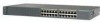
... CONSOLE BERFEOFREERPOCTOWONEMNRAENCUTAINL G DC INPUT ICNUPRURTE: 3N6T:- 72 4-2A A +- Note The Cisco RPS does not support the Catalyst 2924M XL DC switch. Power Connectors You can provide power to an AC power outlet. DC Power Connector The Catalyst 2924M XL DC switch has an internal DC-power converter. For installation instructions, see the "Wiring the DC-Input Power...
... CONSOLE BERFEOFREERPOCTOWONEMNRAENCUTAINL G DC INPUT ICNUPRURTE: 3N6T:- 72 4-2A A +- Note The Cisco RPS does not support the Catalyst 2924M XL DC switch. Power Connectors You can provide power to an AC power outlet. DC Power Connector The Catalyst 2924M XL DC switch has an internal DC-power converter. For installation instructions, see the "Wiring the DC-Input Power...

Hardware Installation Guide
Page 42
... or might be damaged. The power source is not in the RPS documentation. The switches do not recommend the redundant-with-reboot configuration. Cisco RPS Connector Specific Cisco RPS models support specific Catalyst 2900 XL switches: • Cisco RPS 600 (model PWR600-AC-RPS)-supports the Catalyst 2912 XL, 2924C XL, 2924 XL, 2924MF XL, and 2924M XL...
... or might be damaged. The power source is not in the RPS documentation. The switches do not recommend the redundant-with-reboot configuration. Cisco RPS Connector Specific Cisco RPS models support specific Catalyst 2900 XL switches: • Cisco RPS 600 (model PWR600-AC-RPS)-supports the Catalyst 2912 XL, 2924C XL, 2924 XL, 2924MF XL, and 2924M XL...

Hardware Installation Guide
Page 43
... port and adapter pinout information, see the "Connecting to the Console Port" section on the Cisco RPS 300, refer to the Cisco Redundant Power System 300 Hardware Installation Guide. Chapter 1 Product Overview Power Connectors RPS Connector on the Catalyst 2912 LRE and 2924 LRE XL Switches The RPS is a 300W redundant power system that adapter from...
... port and adapter pinout information, see the "Connecting to the Console Port" section on the Cisco RPS 300, refer to the Cisco Redundant Power System 300 Hardware Installation Guide. Chapter 1 Product Overview Power Connectors RPS Connector on the Catalyst 2912 LRE and 2924 LRE XL Switches The RPS is a 300W redundant power system that adapter from...

Hardware Installation Guide
Page 44
Power Connectors Chapter 1 Product Overview 1-24 Catalyst 2900 Series XL Hardware Installation Guide 78-6461-04
Power Connectors Chapter 1 Product Overview 1-24 Catalyst 2900 Series XL Hardware Installation Guide 78-6461-04

Hardware Installation Guide
Page 51
Rear-panel power connector is within the ranges listed in Appendix A, "Technical Specifications." • Airflow around the switch and through the vents is unrestricted. • Temperature around it might be easily read. - Return all packing materials to ports ... the Catalyst 2900 XL and Catalyst 3500 XL Documentation flyer • Cisco Documentation CD-ROM • AC power cord 78-6461-04 Catalyst 2900 Series XL Hardware Installation Guide 2-7 If any item is shipped with these conditions: - Your Catalyst 2900 XL switch is missing or damaged, contact your Cisco representative or...
Rear-panel power connector is within the ranges listed in Appendix A, "Technical Specifications." • Airflow around the switch and through the vents is unrestricted. • Temperature around it might be easily read. - Return all packing materials to ports ... the Catalyst 2900 XL and Catalyst 3500 XL Documentation flyer • Cisco Documentation CD-ROM • AC power cord 78-6461-04 Catalyst 2900 Series XL Hardware Installation Guide 2-7 If any item is shipped with these conditions: - Your Catalyst 2900 XL switch is missing or damaged, contact your Cisco representative or...
Hardware Installation Guide
Page 68
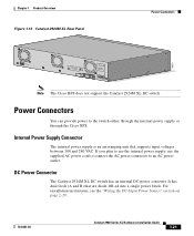
... cord to an AC power outlet. 2-24 As the switch powers on page 2-24. When the switch begins POST, the port LEDs turn amber for 2 seconds, and then they turn green. SERIES 16x 17x 18x 19x 20x 21x 22x 23x 24x Powering On the Switch and Running POST Figure 2-16 Mounting a...the AC power cord to the AC power connector on the switch. Powering On the Switch and Running POST To power on the switch after you install it begins POST, a series of eight tests that run automatically to ensure that the switch functions properly. Catalyst 2900 Series XL Hardware Installation Guide 78-6461-...
... cord to an AC power outlet. 2-24 As the switch powers on page 2-24. When the switch begins POST, the port LEDs turn amber for 2 seconds, and then they turn green. SERIES 16x 17x 18x 19x 20x 21x 22x 23x 24x Powering On the Switch and Running POST Figure 2-16 Mounting a...the AC power cord to the AC power connector on the switch. Powering On the Switch and Running POST To power on the switch after you install it begins POST, a series of eight tests that run automatically to ensure that the switch functions properly. Catalyst 2900 Series XL Hardware Installation Guide 78-6461-...

Hardware Installation Guide
Page 74
... the positive and negative positions for both the A feed wires and the B feed wires. It is already in the DC power connector on the switch back panel. (See Figure 2-21.) Figure 2-21 Terminal Block Plug 60530 Step 2 Identify the positive and negative feed positions for the ...steps for both the A and B feed wires. 2-30 Catalyst 2900 Series XL Hardware Installation Guide 78-6461-04 Note This installation must comply with 5A-branch-circuit protection. Connecting to DC Power Chapter 2 Installation Caution The switch is return to return and negative to negative for wiring the...
... the positive and negative positions for both the A feed wires and the B feed wires. It is already in the DC power connector on the switch back panel. (See Figure 2-21.) Figure 2-21 Terminal Block Plug 60530 Step 2 Identify the positive and negative feed positions for the ...steps for both the A and B feed wires. 2-30 Catalyst 2900 Series XL Hardware Installation Guide 78-6461-04 Note This installation must comply with 5A-branch-circuit protection. Connecting to DC Power Chapter 2 Installation Caution The switch is return to return and negative to negative for wiring the...

Hardware Installation Guide
Page 79
Terminal block plug Tie wrap Connecting to a 10/100 Port The switch 10/100 ports configure themselves to an RJ-45 connector on page B-4. 78-6461-04 Catalyst 2900 Series XL Hardware Installation Guide 2-35 When connecting to a 10/100 Port 74080 CONSOLE BERFEOFREERPOCTOWONEMNRAENCUTAINL G ... to switches or repeaters, use a crossover Category 5 cable. To maximize performance, choose one of these steps to connect to 10BASE-T and 100BASE-TX devices: Step 1 When connecting to workstations, servers, routers, and Cisco IP Phones, connect a straight-through Category 5 cable to ...
Terminal block plug Tie wrap Connecting to a 10/100 Port The switch 10/100 ports configure themselves to an RJ-45 connector on page B-4. 78-6461-04 Catalyst 2900 Series XL Hardware Installation Guide 2-35 When connecting to a 10/100 Port 74080 CONSOLE BERFEOFREERPOCTOWONEMNRAENCUTAINL G ... to switches or repeaters, use a crossover Category 5 cable. To maximize performance, choose one of these steps to connect to 10BASE-T and 100BASE-TX devices: Step 1 When connecting to workstations, servers, routers, and Cisco IP Phones, connect a straight-through Category 5 cable to ...

Hardware Installation Guide
Page 80
... an RJ-45 connector of the cable to it. See Chapter 3, "Troubleshooting," for information about 30 seconds, and then the port LED turns green. Repeat Steps 1 through , twisted-pair cable. Use the LAN-to-phone jack to connect the telephone to each 10/100 port. 2-36 Catalyst 2900 Series XL... one end of the other end might not be a cable problem or a problem with your Cisco IP Phone for solutions to a Cisco IP Phone through a straight-through 3 to connect to the switch. The rear panel of the switch 10/100 port. Connecting to a 10/100 Port Figure 2-28 Connecting to a 10/100...
... an RJ-45 connector of the cable to it. See Chapter 3, "Troubleshooting," for information about 30 seconds, and then the port LED turns green. Repeat Steps 1 through , twisted-pair cable. Use the LAN-to-phone jack to connect the telephone to each 10/100 port. 2-36 Catalyst 2900 Series XL... one end of the other end might not be a cable problem or a problem with your Cisco IP Phone for solutions to a Cisco IP Phone through a straight-through 3 to connect to the switch. The rear panel of the switch 10/100 port. Connecting to a 10/100 Port Figure 2-28 Connecting to a 10/100...
Hardware Installation Guide
Page 81
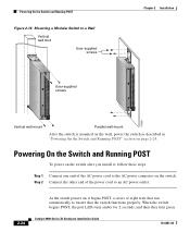
.... You can connect the 100BASE-FX ports to other 100BASE-FX-compatible network devices, such as shown in Figure 2-29. 78-6461-04 Catalyst 2900 Series XL Hardware Installation Guide 2-37 or 62.5/125-micron multimode fiber-optic cable to connect these steps: Step 1 Step 2 Remove ... the port on the 100BASE-FX ports. These ports use a duplex SC connector, and you are ready to the 100BASE-FX port on the switch, as servers, routers, and other switches. The fiber-optic distances between the switch and the attached device follow these ports to other 100BASE-FX devices. Chapter...
.... You can connect the 100BASE-FX ports to other 100BASE-FX-compatible network devices, such as shown in Figure 2-29. 78-6461-04 Catalyst 2900 Series XL Hardware Installation Guide 2-37 or 62.5/125-micron multimode fiber-optic cable to connect these steps: Step 1 Step 2 Remove ... the port on the 100BASE-FX ports. These ports use a duplex SC connector, and you are ready to the 100BASE-FX port on the switch, as servers, routers, and other switches. The fiber-optic distances between the switch and the attached device follow these ports to other 100BASE-FX devices. Chapter...
Hardware Installation Guide
Page 83
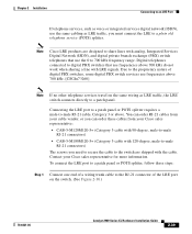
.... [CSCdu73260] Note If no other telephone services travel on the switch. (See Figure 2-30.) 78-6461-04 Catalyst 2900 Series XL Hardware Installation Guide 2-39 Contact your Cisco sales representative: • CAB-5-M120M120-5= (Category 5 cable with 90-degree, male-to-male RJ-21 connectors) • CAB-5-M180M120-5= (Category 5 cable with 120-degree, male-to...
.... [CSCdu73260] Note If no other telephone services travel on the switch. (See Figure 2-30.) 78-6461-04 Catalyst 2900 Series XL Hardware Installation Guide 2-39 Contact your Cisco sales representative: • CAB-5-M120M120-5= (Category 5 cable with 90-degree, male-to-male RJ-21 connectors) • CAB-5-M180M120-5= (Category 5 cable with 120-degree, male-to...