
Hardware Installation Guide
Page 11
... Ethernet and local area networking. Chapter 2, "Installation," provides the procedures for installing and configuring a Catalyst 2900 series XL switch. Preface Audience This guide is organized into the following chapters: Chapter 1, "Product Overview," summarizes the switch features and describes the ports, the standards they support, and the LEDs. We assume that might arise when you are installing the switch. 78-6461-04 Catalyst 2900 Series XL Hardware Installation Guide xi Chapter 3, "Troubleshooting...
... Ethernet and local area networking. Chapter 2, "Installation," provides the procedures for installing and configuring a Catalyst 2900 series XL switch. Preface Audience This guide is organized into the following chapters: Chapter 1, "Product Overview," summarizes the switch features and describes the ports, the standards they support, and the LEDs. We assume that might arise when you are installing the switch. 78-6461-04 Catalyst 2900 Series XL Hardware Installation Guide xi Chapter 3, "Troubleshooting...

Hardware Installation Guide
Page 21
...-FX ports • Checks for errors on a received packet, determines the destination port, stores the packet in shared memory, and then forwards the packet to which you can be deployed as backbone switches, aggregating 10/100 and Gigabit Ethernet traffic from other switches. The 2900 XL LRE switches employ Long-Reach Ethernet (LRE), a very-high-data-rate digital subscriber line (VDSL)-based technology that describe the Catalyst 2900 series XL switches, hereafter referred...
...-FX ports • Checks for errors on a received packet, determines the destination port, stores the packet in shared memory, and then forwards the packet to which you can be deployed as backbone switches, aggregating 10/100 and Gigabit Ethernet traffic from other switches. The 2900 XL LRE switches employ Long-Reach Ethernet (LRE), a very-high-data-rate digital subscriber line (VDSL)-based technology that describe the Catalyst 2900 series XL switches, hereafter referred...

Hardware Installation Guide
Page 22
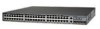
... LRE ports through one RJ-21 connector and hot swapping capability with the Cisco LRE customer premises equipment (CPE) devices • Supports up to 2048 MAC addresses on the Catalyst 2924 XL, 2924C XL, and 2912 XL switches • Supports up to 8192 MAC addresses on the Catalyst 2924M XL, Catalyst 2924M XL DC and Catalyst 2912MF XL switches Figure 1-1 shows the switch models. Catalyst 2900 Series XL Hardware Installation Guide...
... LRE ports through one RJ-21 connector and hot swapping capability with the Cisco LRE customer premises equipment (CPE) devices • Supports up to 2048 MAC addresses on the Catalyst 2924 XL, 2924C XL, and 2912 XL switches • Supports up to 8192 MAC addresses on the Catalyst 2924M XL, Catalyst 2924M XL DC and Catalyst 2912MF XL switches Figure 1-1 shows the switch models. Catalyst 2900 Series XL Hardware Installation Guide...

Hardware Installation Guide
Page 24
... switch console port or by using Telnet from the CLI. Front-Panel Description Depending on the switch. Using CMS, you can also display network topologies to gather link information and to display switch images to monitor and control the switch and switch cluster members. You can have a set of LEDs and a Mode button. This section describes these interfaces: • Cluster Management Suite (CMS)-CMS is enhanced to the Catalyst 2900 Series XL and Catalyst...
... switch console port or by using Telnet from the CLI. Front-Panel Description Depending on the switch. Using CMS, you can also display network topologies to gather link information and to display switch images to monitor and control the switch and switch cluster members. You can have a set of LEDs and a Mode button. This section describes these interfaces: • Cluster Management Suite (CMS)-CMS is enhanced to the Catalyst 2900 Series XL and Catalyst...

Hardware Installation Guide
Page 26
... Catalyst 2900 Series XL and Catalyst 3500 Series XL Software Configuration Guide for more info on the Catalyst 2900 XL switches provide protocol support for the cables are described in any compatible network device up to operate in Appendix B, "Connectors and Cable Specifications." Cisco IP Phones-connected to the 10/100 port-must be set for speed and duplex autonegotiation, compliant with IEEE 802.3U. When connecting the switch to workstations, servers, routers, and Cisco...
... Catalyst 2900 Series XL and Catalyst 3500 Series XL Software Configuration Guide for more info on the Catalyst 2900 XL switches provide protocol support for the cables are described in any compatible network device up to operate in Appendix B, "Connectors and Cable Specifications." Cisco IP Phones-connected to the 10/100 port-must be set for speed and duplex autonegotiation, compliant with IEEE 802.3U. When connecting the switch to workstations, servers, routers, and Cisco...

Hardware Installation Guide
Page 27
...: • If the switch port and the port on the attached device are configured for half-duplex operation, the connection can be used. For more information about configuring the LRE ports, refer to private telephone networks and the public system telephone network 78-6461-04 Catalyst 2900 Series XL Hardware Installation Guide 1-7 If telephone services, such as plain old telephone service (POTS) splitter. You can connect Cisco 575 LRE CPE and...
...: • If the switch port and the port on the attached device are configured for half-duplex operation, the connection can be used. For more information about configuring the LRE ports, refer to private telephone networks and the public system telephone network 78-6461-04 Catalyst 2900 Series XL Hardware Installation Guide 1-7 If telephone services, such as plain old telephone service (POTS) splitter. You can connect Cisco 575 LRE CPE and...

Hardware Installation Guide
Page 29
... start the module by each port LED. Catalyst 2900 Series XL Hardware Installation Guide 1-9 After the restart, the switch address capacity is working properly before it starts forwarding packets. Refer to 2048 MAC addresses. You can use to select a port mode. Figure 1-5, Figure 1-6, and Figure 1-7 show the location of these modules in module slots and tighten the thumb screws. Chapter 1 Product Overview Front-Panel Description Table 1-1 Expansion Modules (continued) Module Type Model Number 1000BASE-T 1Ethernet Gigabit WS-X2932...
... start the module by each port LED. Catalyst 2900 Series XL Hardware Installation Guide 1-9 After the restart, the switch address capacity is working properly before it starts forwarding packets. Refer to 2048 MAC addresses. You can use to select a port mode. Figure 1-5, Figure 1-6, and Figure 1-7 show the location of these modules in module slots and tighten the thumb screws. Chapter 1 Product Overview Front-Panel Description Table 1-1 Expansion Modules (continued) Module Type Model Number 1000BASE-T 1Ethernet Gigabit WS-X2932...

Hardware Installation Guide
Page 33
... fan in standby mode. If the switch power supply fails, the switch powers down and after 15 seconds restarts, using power from the RPS. Figure 1-8 RPS LED on the Catalyst 2912 LRE XL and 2924 LRE XL Switches Color Off Solid green Blinking green RPS Status RPS is not a recommended configuration. The switch goes through its normal boot sequence when it in Ready mode, and the LED should turn green. • One of the power supplies...
... fan in standby mode. If the switch power supply fails, the switch powers down and after 15 seconds restarts, using power from the RPS. Figure 1-8 RPS LED on the Catalyst 2912 LRE XL and 2924 LRE XL Switches Color Off Solid green Blinking green RPS Status RPS is not a recommended configuration. The switch goes through its normal boot sequence when it in Ready mode, and the LED should turn green. • One of the power supplies...

Hardware Installation Guide
Page 34
When you change a mode, press the Mode button until the desired mode is the default mode. Table 1-6 and Table 1-7 list the port LED colors. Contact Cisco Systems. The internal power supply in a switch has failed, and the RPS is in standby mode or in use by the switch. (See Figure 1-8.) The port duplex mode: full duplex or half duplex, and default modes: • 10/100 ports: auto • 100BaseFX ports: auto • Gigabit ports: auto The port operating speed: 10 or 100 Mbps. 1-14 Catalyst 2900 Series XL Hardware Installation Guide 78...
When you change a mode, press the Mode button until the desired mode is the default mode. Table 1-6 and Table 1-7 list the port LED colors. Contact Cisco Systems. The internal power supply in a switch has failed, and the RPS is in standby mode or in use by the switch. (See Figure 1-8.) The port duplex mode: full duplex or half duplex, and default modes: • 10/100 ports: auto • 100BaseFX ports: auto • Gigabit ports: auto The port operating speed: 10 or 100 Mbps. 1-14 Catalyst 2900 Series XL Hardware Installation Guide 78...

Hardware Installation Guide
Page 35
... default setting is auto. 78-6461-04 Catalyst 2900 Series XL Hardware Installation Guide 1-15 The port operating speed: 10 or 100 Mbps. Default mode on the Catalyst 2912 LRE XL and Catalyst 2924 LRE XL continue to show Ethernet link status. The default setting is half duplex. Chapter 1 Product Overview Front-Panel Description Table 1-5 Port Mode LEDs on Catalyst 2912 LRE XL and 2924 LRE XL Switches Mode LED LRE STAT DUPLX SPEED Port Mode LRE link status Port status Port duplex mode Port speed Description Long-Reach Ethernet (LRE) link status...
... default setting is auto. 78-6461-04 Catalyst 2900 Series XL Hardware Installation Guide 1-15 The port operating speed: 10 or 100 Mbps. Default mode on the Catalyst 2912 LRE XL and Catalyst 2924 LRE XL continue to show Ethernet link status. The default setting is half duplex. Chapter 1 Product Overview Front-Panel Description Table 1-5 Port Mode LEDs on Catalyst 2912 LRE XL and 2924 LRE XL Switches Mode LED LRE STAT DUPLX SPEED Port Mode LRE link status Port status Port duplex mode Port speed Description Long-Reach Ethernet (LRE) link status...
Hardware Installation Guide
Page 36
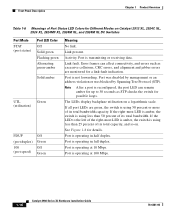
... (port duplex) 100 (port speed) Off Green Off Green Meaning No link. Activity. Front-Panel Description Chapter 1 Product Overview Table 1-6 Meanings of Port Status LED Colors for details. Port is operating at 10 Mbps. See Figure 1-8 for Different Modes on a logarithmic scale. Link present. If the right-most LED is amber, the switch is operating at 100 Mbps. 1-16 Catalyst 2900 Series XL Hardware Installation Guide 78-6461-04 Port was disabled by management or...
... (port duplex) 100 (port speed) Off Green Off Green Meaning No link. Activity. Front-Panel Description Chapter 1 Product Overview Table 1-6 Meanings of Port Status LED Colors for details. Port is operating at 10 Mbps. See Figure 1-8 for Different Modes on a logarithmic scale. Link present. If the right-most LED is amber, the switch is operating at 100 Mbps. 1-16 Catalyst 2900 Series XL Hardware Installation Guide 78-6461-04 Port was disabled by management or...

Hardware Installation Guide
Page 38
... -12.4%+ 12.5 -24%+ 25 - 49%+ 50%+ Catalyst 2900 SERIES XL 1-18 Catalyst 2900 Series XL Hardware Installation Guide 78-6461-04 Figure 1-9 shows bandwidth utilization percentages displayed by the right-most LEDs. Green LRE port or remote CPE Ethernet port is operating at 100 Mbps. 1. To verify the LRE CPE Ethernet link status from a switch with Cisco IOS Release 12.0(5.x)WC1 or Cisco IOS Release 12.0(5.x)WC2 provide information...
... -12.4%+ 12.5 -24%+ 25 - 49%+ 50%+ Catalyst 2900 SERIES XL 1-18 Catalyst 2900 Series XL Hardware Installation Guide 78-6461-04 Figure 1-9 shows bandwidth utilization percentages displayed by the right-most LEDs. Green LRE port or remote CPE Ethernet port is operating at 100 Mbps. 1. To verify the LRE CPE Ethernet link status from a switch with Cisco IOS Release 12.0(5.x)WC1 or Cisco IOS Release 12.0(5.x)WC2 provide information...

Hardware Installation Guide
Page 51
... of the expansion modules, refer to the modules documentation in Appendix A, "Technical Specifications." • Airflow around the switch and through the vents is unrestricted. • Temperature around it might be easily read. - Return all packing materials to ports is sufficient for unrestricted cabling. - Chapter 2 Installation Preparing for Installation • For Long-Reach Ethernet (LRE) ports, cable lengths from the switch to the connected Ethernet device are...
... of the expansion modules, refer to the modules documentation in Appendix A, "Technical Specifications." • Airflow around the switch and through the vents is unrestricted. • Temperature around it might be easily read. - Return all packing materials to ports is sufficient for unrestricted cabling. - Chapter 2 Installation Preparing for Installation • For Long-Reach Ethernet (LRE) ports, cable lengths from the switch to the connected Ethernet device are...

Hardware Installation Guide
Page 79
... support autonegotiation, you can explicitly set can reduce performance or result in the "Cable and Adapter Specifications" section on page B-4. 78-6461-04 Catalyst 2900 Series XL Hardware Installation Guide 2-35 Chapter 2 Installation Figure 2-27 Inserting Terminal Block Into Switch Connecting to switches or repeaters, use a crossover Category 5 cable. To maximize performance, choose one of these steps to connect to 10BASE-T and 100BASE-TX devices: Step 1 When connecting to workstations, servers, routers...
... support autonegotiation, you can explicitly set can reduce performance or result in the "Cable and Adapter Specifications" section on page B-4. 78-6461-04 Catalyst 2900 Series XL Hardware Installation Guide 2-35 Chapter 2 Installation Figure 2-27 Inserting Terminal Block Into Switch Connecting to switches or repeaters, use a crossover Category 5 cable. To maximize performance, choose one of these steps to connect to 10BASE-T and 100BASE-TX devices: Step 1 When connecting to workstations, servers, routers...
Hardware Installation Guide
Page 82
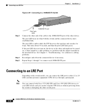
... searches for solutions to cabling problems. Reconfigure and reboot the connected device if necessary. See Chapter 3, "Troubleshooting," for loops. The port LED turns on when both Cisco 575 LRE CPE and Cisco 585 LRE CPE devices to your LRE switch, and you can hot swap the CPE devices without powering down the switch or disrupting the other switch ports. 2-38 Catalyst 2900 Series XL Hardware Installation Guide 78-6461-04...
... searches for solutions to cabling problems. Reconfigure and reboot the connected device if necessary. See Chapter 3, "Troubleshooting," for loops. The port LED turns on when both Cisco 575 LRE CPE and Cisco 585 LRE CPE devices to your LRE switch, and you can hot swap the CPE devices without powering down the switch or disrupting the other switch ports. 2-38 Catalyst 2900 Series XL Hardware Installation Guide 78-6461-04...
Hardware Installation Guide
Page 85
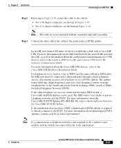
...-48), refer to the Catalyst 2900 Series XL and Catalyst 3500 Series XL Software Configuration Guide. For more information about homologated POTS splitters, contact your Cisco sales representative. Each LRE port status LED turns on when it establishes a link with the connector and cable assembly. If the installation does not have a PBX, a homologated POTS splitter is required to directly connect to the patch panel through a PBX switch, a Cisco LRE...
...-48), refer to the Catalyst 2900 Series XL and Catalyst 3500 Series XL Software Configuration Guide. For more information about homologated POTS splitters, contact your Cisco sales representative. Each LRE port status LED turns on when it establishes a link with the connector and cable assembly. If the installation does not have a PBX, a homologated POTS splitter is required to directly connect to the patch panel through a PBX switch, a Cisco LRE...

Hardware Installation Guide
Page 86
... setup program. See the Catalyst 2900 Series XL and Catalyst 3500 Series XL Software Configuration Guide for instructions. 2-42 Catalyst 2900 Series XL Hardware Installation Guide 78-6461-04 Connecting to the Console Port Use the supplied rollover cable and DB-9 adapter to connect a PC to the Catalyst 2900 Series XL Modules Installation Guide and the Catalyst 2900 Series XL ATM Modules Installation and Configuration Guide. or terminal-emulation software to -DB-25 female DTE adapter if you can order a kit (part number ACS-DSBUASYN=) containing that adapter from Cisco. Configure...
... setup program. See the Catalyst 2900 Series XL and Catalyst 3500 Series XL Software Configuration Guide for instructions. 2-42 Catalyst 2900 Series XL Hardware Installation Guide 78-6461-04 Connecting to the Console Port Use the supplied rollover cable and DB-9 adapter to connect a PC to the Catalyst 2900 Series XL Modules Installation Guide and the Catalyst 2900 Series XL ATM Modules Installation and Configuration Guide. or terminal-emulation software to -DB-25 female DTE adapter if you can order a kit (part number ACS-DSBUASYN=) containing that adapter from Cisco. Configure...
Hardware Installation Guide
Page 89
... forwarding packets. When the switch begins its POST, the port status LEDs turn green. The port status LEDs for details. They show failures in turn as the system completes a test. 78-6461-04 Catalyst 2900 Series XL Hardware Installation Guide 3-1 You can also get statistics from the browser interface, from the command-line interface (CLI), or from an SNMP workstation. See the Catalyst 2900 Series XL and Catalyst 3500 Series XL Software Configuration Guide, the Catalyst 2900 Series XL and Catalyst 3500 Series XL Command Reference...
... forwarding packets. When the switch begins its POST, the port status LEDs turn green. The port status LEDs for details. They show failures in turn as the system completes a test. 78-6461-04 Catalyst 2900 Series XL Hardware Installation Guide 3-1 You can also get statistics from the browser interface, from the command-line interface (CLI), or from an SNMP workstation. See the Catalyst 2900 Series XL and Catalyst 3500 Series XL Software Configuration Guide, the Catalyst 2900 Series XL and Catalyst 3500 Series XL Command Reference...
Hardware Installation Guide
Page 95
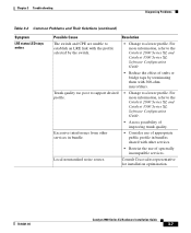
... Catalyst 2900 Series XL Hardware Installation Guide 3-7 Local nonstandard noise source. For more information, refer to a lower profile. Excessive interference from other services. • Restrict the use of appropriate public profile in bundles shared with the profile selected by terminating them with 300-ohm microfilters. Chapter 3 Troubleshooting Diagnosing Problems Table 3-2 Common Problems and Their Solutions (continued) Symptom LRE status LED stays amber. Possible Cause Resolution The switch...
... Catalyst 2900 Series XL Hardware Installation Guide 3-7 Local nonstandard noise source. For more information, refer to a lower profile. Excessive interference from other services. • Restrict the use of appropriate public profile in bundles shared with the profile selected by terminating them with 300-ohm microfilters. Chapter 3 Troubleshooting Diagnosing Problems Table 3-2 Common Problems and Their Solutions (continued) Symptom LRE status LED stays amber. Possible Cause Resolution The switch...

Hardware Installation Guide
Page 111
...-45-to-DB-9 Terminal Adapter DB-9 Pin 8 6 2 5 5 3 4 7 Console Device Signal CTS DSR RxD GND GND TxD DTR RTS Connecting to a Terminal Use the thin, flat, RJ-45-to-RJ-45 rollover cable and RJ-45-to-DB-25 female DTE adapter to connect the console port to a terminal. You can order a kit (part number ACS-DSBUASYN=) containing this adapter from Cisco. 78-6461-04 Catalyst 2900 Series XL Hardware Installation Guide B-7
...-45-to-DB-9 Terminal Adapter DB-9 Pin 8 6 2 5 5 3 4 7 Console Device Signal CTS DSR RxD GND GND TxD DTR RTS Connecting to a Terminal Use the thin, flat, RJ-45-to-RJ-45 rollover cable and RJ-45-to-DB-25 female DTE adapter to connect the console port to a terminal. You can order a kit (part number ACS-DSBUASYN=) containing this adapter from Cisco. 78-6461-04 Catalyst 2900 Series XL Hardware Installation Guide B-7

