
Configuration Guide
Page 1
VIEW Certified Configuration Guide Cisco 2100/4400/5500 Series WLC (Wireless LAN Controller), WiSM (Wireless Services Module) and 3750G Integrated WLC with 1100, 1130, 1140, 1200, 1230, 1240, 1250 APs October 2010 Edition 1725-36192-001 Version H
VIEW Certified Configuration Guide Cisco 2100/4400/5500 Series WLC (Wireless LAN Controller), WiSM (Wireless Services Module) and 3750G Integrated WLC with 1100, 1130, 1140, 1200, 1230, 1240, 1250 APs October 2010 Edition 1725-36192-001 Version H

Configuration Guide
Page 2
... registered and/or common law marks in any form or by any means, for use , without the express written permission of Polycom, Inc. VIEW Certified Configuration Guide Patent Information The accompanying product is protected by one or more US and foreign patents and/or pending patent applications held by Polycom personnel...
... registered and/or common law marks in any form or by any means, for use , without the express written permission of Polycom, Inc. VIEW Certified Configuration Guide Patent Information The accompanying product is protected by one or more US and foreign patents and/or pending patent applications held by Polycom personnel...

Configuration Guide
Page 3
Cisco Wireless LAN Controllers with 1100, 1130, 1140, 1200, 1230, 1240, 1250 APs Contents Overview...4 Certified Product Summary 4 Known Limitations 5 Polycom References 5 Product Support 6 Section 1: Configuration for SVP Operation 7 Network Topology 7 Configuring a New Controller Starting from Factory Defaults 7 Connecting to the Controller Via a Browser 8 Installing Software 9 Controller Setup 9 Connecting APs 10 AP Configuration 11 Setting up...
Cisco Wireless LAN Controllers with 1100, 1130, 1140, 1200, 1230, 1240, 1250 APs Contents Overview...4 Certified Product Summary 4 Known Limitations 5 Polycom References 5 Product Support 6 Section 1: Configuration for SVP Operation 7 Network Topology 7 Configuring a New Controller Starting from Factory Defaults 7 Connecting to the Controller Via a Browser 8 Installing Software 9 Controller Setup 9 Connecting APs 10 AP Configuration 11 Setting up...

Configuration Guide
Page 4
... for screen captures for software version 5.2.193.0. 4 PN: 1725-36192-001_H This guide describes the configuration of this document are for Enterprise Wireless (VIEW) Certification Program is designed to ensure interoperability and high performance between SpectraLink Wireless Telephones and WLAN infrastructure products. VIEW Certified Configuration Guide Overview Polycom's Voice Interoperability for Cisco software version 6.0.199.4.
... for screen captures for software version 5.2.193.0. 4 PN: 1725-36192-001_H This guide describes the configuration of this document are for Enterprise Wireless (VIEW) Certification Program is designed to ensure interoperability and high performance between SpectraLink Wireless Telephones and WLAN infrastructure products. VIEW Certified Configuration Guide Overview Polycom's Voice Interoperability for Cisco software version 6.0.199.4.

Configuration Guide
Page 6
Screen captures included in Lightweight mode, see Cisco Aironet Access Point Support for Lightweight Access Point Protocol [Cisco Aironet 1130 AG Series] and Cisco Aironet Access Point Support for Cisco software version 6.0.199.4. Once the APs are for Lightweight Access Point Protocol [Cisco Aironet 1240 AG Series]. 4. This document does not cover the steps involved to provision APs. To convert the Cisco 1200 Series Autonomous AP to Lightweight mode...
Screen captures included in Lightweight mode, see Cisco Aironet Access Point Support for Lightweight Access Point Protocol [Cisco Aironet 1130 AG Series] and Cisco Aironet Access Point Support for Cisco software version 6.0.199.4. Once the APs are for Lightweight Access Point Protocol [Cisco Aironet 1240 AG Series]. 4. This document does not cover the steps involved to provision APs. To convert the Cisco 1200 Series Autonomous AP to Lightweight mode...
Configuration Guide
Page 7
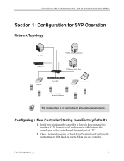
...Open a terminal program, such as Hyper Terminal, and configure the port settings to all customer environments. Cisco Wireless LAN Controllers with 1100, 1130, 1140, 1200, 1230, 1240, 1250 APs Section 1: Configuration for SVP Operation Network Topology SIP PBX RADIUS Authentication Server ... STATUS ALARM LINK PS1 ACT PS2 UTILITY LINK ACT 1 2 Cisco WLC Cisco 4400 Series WIRELESS LAN CONTROLLER MODEL 4402 50 AP SpectraLink 8000 series Wireless Telephones Wireless Data Client Cisco AP This configuration is done via the command line interface (CLI). Initial provisioning of...
...Open a terminal program, such as Hyper Terminal, and configure the port settings to all customer environments. Cisco Wireless LAN Controllers with 1100, 1130, 1140, 1200, 1230, 1240, 1250 APs Section 1: Configuration for SVP Operation Network Topology SIP PBX RADIUS Authentication Server ... STATUS ALARM LINK PS1 ACT PS2 UTILITY LINK ACT 1 2 Cisco WLC Cisco 4400 Series WIRELESS LAN CONTROLLER MODEL 4402 50 AP SpectraLink 8000 series Wireless Telephones Wireless Data Client Cisco AP This configuration is done via the command line interface (CLI). Initial provisioning of...

Configuration Guide
Page 8
... the Controller Via a Browser 1. Connect to the WLC by pointing your internet browser to the Installation and Startup Guide for the 4400: http://www.cisco.com/en/US/docs/wireless/controller/4400/quic k/guide/ctrlv32.html#wp34023 5. Click the Login prompt. VIEW Certified Configuration Guide 3. Connecting to perform initial controller setup and provisioning. Once...
... the Controller Via a Browser 1. Connect to the WLC by pointing your internet browser to the Installation and Startup Guide for the 4400: http://www.cisco.com/en/US/docs/wireless/controller/4400/quic k/guide/ctrlv32.html#wp34023 5. Click the Login prompt. VIEW Certified Configuration Guide 3. Connecting to perform initial controller setup and provisioning. Once...

Configuration Guide
Page 10
...to hand out leases to the connected clients. (Note: The WLC's DHCP server does not lease addresses to the AP.) The instructions for the configuration shown in the diagram only. From the main menu, click Controller. 10 PN: 1725-36192-001_H Connecting APs As the APs are for doing so... are included at the end of this document are connected to the network, they should include the DHCP server you can configure a DHCP server to Multicast and enter a multicast IP address that is currently not being used on a remote PC for large-scale deployments, an ...
...to hand out leases to the connected clients. (Note: The WLC's DHCP server does not lease addresses to the AP.) The instructions for the configuration shown in the diagram only. From the main menu, click Controller. 10 PN: 1725-36192-001_H Connecting APs As the APs are for doing so... are included at the end of this document are connected to the network, they should include the DHCP server you can configure a DHCP server to Multicast and enter a multicast IP address that is currently not being used on a remote PC for large-scale deployments, an ...

Configuration Guide
Page 11
...Information, enter the IP address of the Primary DHCP Server. 5. All APs supporting the handsets must have the same QoS setting. Section 1: SVP Cisco Wireless LAN Controllers with 1100, 1130, 1140, 1200, 1230, 1240, 1250 APs 2. From the main menu, click Monitor. Verify that the proper ...IP addresses are associated to find the controller. 2. Power-on a given AP radio must be configured to the interfaces. 3. PN: 1725-36192-001_H 11 In the navigation pane, click Interfaces. Under Interface Name click management. 4. Repeat this...
...Information, enter the IP address of the Primary DHCP Server. 5. All APs supporting the handsets must have the same QoS setting. Section 1: SVP Cisco Wireless LAN Controllers with 1100, 1130, 1140, 1200, 1230, 1240, 1250 APs 2. From the main menu, click Monitor. Verify that the proper ...IP addresses are associated to find the controller. 2. Power-on a given AP radio must be configured to the interfaces. 3. PN: 1725-36192-001_H 11 In the navigation pane, click Interfaces. Under Interface Name click management. 4. Repeat this...

Configuration Guide
Page 12
VIEW Certified Configuration Guide Configuration for the access point you wish to change. 12 PN: 1725-36192-001_H All the APs that are connected should be listed, showing their Operational Status as UP. 3. In the navigation pane, under Access Points click Radios, then select 802.11b/g/n. Select Configure from the drop-down list for handsets running in 802.11b & b/g mixed mode 1. From the main menu, click Wireless. 2.
VIEW Certified Configuration Guide Configuration for the access point you wish to change. 12 PN: 1725-36192-001_H All the APs that are connected should be listed, showing their Operational Status as UP. 3. In the navigation pane, under Access Points click Radios, then select 802.11b/g/n. Select Configure from the drop-down list for handsets running in 802.11b & b/g mixed mode 1. From the main menu, click Wireless. 2.

Configuration Guide
Page 13
... and Tx Power Level Assignment were not tested. Configure any other settings that might be re- Click the Apply button to support the corresponding Mandatory data rate setting in the access point. SpectraLink Wireless Telephones require the following minimum dBm reading to save... Screenshot for 1100, 1130, 1200, 1230 and 1240 series access points: Screenshot for wireless voice traffic - PN: 1725-36192-001_H 13 enabled after setting radio parameters. Set Admin Status to support all changes. Section 1: SVP Cisco Wireless LAN Controllers with 1100, 1130, 1140, 1200, 1230,...
... and Tx Power Level Assignment were not tested. Configure any other settings that might be re- Click the Apply button to support the corresponding Mandatory data rate setting in the access point. SpectraLink Wireless Telephones require the following minimum dBm reading to save... Screenshot for 1100, 1130, 1200, 1230 and 1240 series access points: Screenshot for wireless voice traffic - PN: 1725-36192-001_H 13 enabled after setting radio parameters. Set Admin Status to support all changes. Section 1: SVP Cisco Wireless LAN Controllers with 1100, 1130, 1140, 1200, 1230,...

Configuration Guide
Page 14
... to match the highest transmit power of the APs. Use the default Fragmentation Threshold (2346 bytes). 10. The handset power should be configured to save the settings. 12. VIEW Certified Configuration Guide 802.11 Radio Standard 802.11b 802.11g 802.11a Minimum Available Signal Strength (RSSI) -70 dBm -60 dBm -63... Apply button to save the settings. 15. Set the Beacon Period to 100. 11. Enable 802.11b/g Network Status and 802.11g Support if SpectraLink Wireless Telephones are configured for Deploying SpectraLink 8020/8030...
... to match the highest transmit power of the APs. Use the default Fragmentation Threshold (2346 bytes). 10. The handset power should be configured to save the settings. 12. VIEW Certified Configuration Guide 802.11 Radio Standard 802.11b 802.11g 802.11a Minimum Available Signal Strength (RSSI) -70 dBm -60 dBm -63... Apply button to save the settings. 15. Set the Beacon Period to 100. 11. Enable 802.11b/g Network Status and 802.11g Support if SpectraLink Wireless Telephones are configured for Deploying SpectraLink 8020/8030...

Configuration Guide
Page 15
...the access point you wish to save all changes. In the navigation pane, under Access Points click Radios, then select 802.11a /n. Configure any other settings that are connected should be relevant to your facility's RF site survey - Click the Apply button to change. Global settings for wireless ...Custom Tx Power and RF Channel settings please consult your deployment as UP. 3. Section 1: SVP Cisco Wireless LAN Controllers with 1100, 1130, 1140, 1200, 1230, 1240, 1250 APs Configuration for each AP using non-overlapping channels. 4. All the APs that might be listed, showing ...
...the access point you wish to save all changes. In the navigation pane, under Access Points click Radios, then select 802.11a /n. Configure any other settings that are connected should be relevant to your facility's RF site survey - Click the Apply button to change. Global settings for wireless ...Custom Tx Power and RF Channel settings please consult your deployment as UP. 3. Section 1: SVP Cisco Wireless LAN Controllers with 1100, 1130, 1140, 1200, 1230, 1240, 1250 APs Configuration for each AP using non-overlapping channels. 4. All the APs that might be listed, showing ...

Configuration Guide
Page 16
...your facility's RF site survey, designed for 1140 and 1250 series access points: 7. Set 802.11a Network Status to support all data rates. VIEW Certified Configuration Guide Screenshot for 1100, 1130, 1200, 1230 and 1240 series access points: Screenshot for voice traffic, to determine if you have sufficient ...enabled after setting radio parameters 9. The handset requires the following minimum dBm reading to support the corresponding Mandatory data rate setting in the access point. 802.11 Radio Standard 802.11b 802.11g 802.11a Minimum Available Signal Strength (RSSI) -70 dBm -60 dBm -63 ...
...your facility's RF site survey, designed for 1140 and 1250 series access points: 7. Set 802.11a Network Status to support all data rates. VIEW Certified Configuration Guide Screenshot for 1100, 1130, 1200, 1230 and 1240 series access points: Screenshot for voice traffic, to determine if you have sufficient ...enabled after setting radio parameters 9. The handset requires the following minimum dBm reading to support the corresponding Mandatory data rate setting in the access point. 802.11 Radio Standard 802.11b 802.11g 802.11a Minimum Available Signal Strength (RSSI) -70 dBm -60 dBm -63 ...

Configuration Guide
Page 17
... Best Practices Guide for Quality of Service. The handset power should be configured to match the highest transmit power of Service and the data SSID must be set to Silver for Deploying SpectraLink 8020/8030 Wireless Telephones. 10. In the navigation pane under 802.11a/n, select EDCA ...that is set to Platinum for Quality of the APs. 13. In the navigation pane under 802.11a /n, select Network. 18. Section 1: SVP Cisco Wireless LAN Controllers with 1100, 1130, 1140, 1200, 1230, 1240, 1250 APs For additional details on separate SSIDs to prioritize voice traffic. The voice...
... Best Practices Guide for Quality of Service. The handset power should be configured to match the highest transmit power of Service and the data SSID must be set to Silver for Deploying SpectraLink 8020/8030 Wireless Telephones. 10. In the navigation pane under 802.11a/n, select EDCA ...that is set to Platinum for Quality of the APs. 13. In the navigation pane under 802.11a /n, select Network. 18. Section 1: SVP Cisco Wireless LAN Controllers with 1100, 1130, 1140, 1200, 1230, 1240, 1250 APs For additional details on separate SSIDs to prioritize voice traffic. The voice...

Configuration Guide
Page 18
... Apply button. 5. Under the General tab, verify the Radio Policy corresponds to the SpectraLink Wireless Telephone configuration. When Radio Policy is configured for 802.11b/g only, the handsets should be configured for 802.11b & b/g mixed. When Radio Policy is configured for the voice SSID. 6. From the main menu, click WLANs. 2. Select the Profile...
... Apply button. 5. Under the General tab, verify the Radio Policy corresponds to the SpectraLink Wireless Telephone configuration. When Radio Policy is configured for 802.11b/g only, the handsets should be configured for 802.11b & b/g mixed. When Radio Policy is configured for the voice SSID. 6. From the main menu, click WLANs. 2. Select the Profile...

Configuration Guide
Page 20
... and WPA2-PSK policies. down list. Select the TKIP check box for the radio that corresponds to the SpectraLink Wireless Telephone configuration. For WPA2-Enterprise (802.1X), under WPA+WPA2 Parameters: i. VIEW Certified Configuration Guide b. iii. c Uncheck the Client Load Balancing and Client Band Select boxes. 20 PN: 1725-36192-001_H Select the...
... and WPA2-PSK policies. down list. Select the TKIP check box for the radio that corresponds to the SpectraLink Wireless Telephone configuration. For WPA2-Enterprise (802.1X), under WPA+WPA2 Parameters: i. VIEW Certified Configuration Guide b. iii. c Uncheck the Client Load Balancing and Client Band Select boxes. 20 PN: 1725-36192-001_H Select the...

Configuration Guide
Page 23
... PBX RADIUS Authentication Server (for WPA2-Enterprise Security) TFTP Server, DHCP Server Cisco AP LINK ACT SERVICE CONSOLE STATUS ALARM LINK PS1 ACT PS2 UTILITY LINK ACT 1 2 Cisco WLC Cisco 4400 Series WIRELESS LAN CONTROLLER MODEL 4402 50 AP SpectraLink 8000 series Wireless Telephones Wireless Data Client Cisco AP This configuration is not applicable to all customer environments.
... PBX RADIUS Authentication Server (for WPA2-Enterprise Security) TFTP Server, DHCP Server Cisco AP LINK ACT SERVICE CONSOLE STATUS ALARM LINK PS1 ACT PS2 UTILITY LINK ACT 1 2 Cisco WLC Cisco 4400 Series WIRELESS LAN CONTROLLER MODEL 4402 50 AP SpectraLink 8000 series Wireless Telephones Wireless Data Client Cisco AP This configuration is not applicable to all customer environments.

Configuration Guide
Page 24
...logged in via the Startup Wizard, the remaining configuration can be configured through the switch-web interface using a Web browser (Cisco recommends using the Startup Wizard for the 4400: http://www.cisco.com/en/US/docs/wireless/controller/4400/quic k/guide/ctrlv32.html#wp34023 ...5. To reset the WLC to factory default, you to factory defaults. Connect to the WLC by pointing...
...logged in via the Startup Wizard, the remaining configuration can be configured through the switch-web interface using a Web browser (Cisco recommends using the Startup Wizard for the 4400: http://www.cisco.com/en/US/docs/wireless/controller/4400/quic k/guide/ctrlv32.html#wp34023 ...5. To reset the WLC to factory default, you to factory defaults. Connect to the WLC by pointing...

Configuration Guide
Page 26
...must be made. Set the Ethernet Multicast Mode to configure each AP individually. Reboot the Controller. Click Save Configuration. 26 PN: 1725-36192-001_H The WLC is capable of the controller is currently not being used on your network for the configuration shown in the diagram only. Click the Apply button.... 4. Controller Setup The initial setup of provisioning the APs. 1. VIEW Certified Configuration Guide 12. It is not necessary to Multicast and enter a multicast IP address that is shown below. The setup instructions outlined ...
...must be made. Set the Ethernet Multicast Mode to configure each AP individually. Reboot the Controller. Click Save Configuration. 26 PN: 1725-36192-001_H The WLC is capable of the controller is currently not being used on your network for the configuration shown in the diagram only. Click the Apply button.... 4. Controller Setup The initial setup of provisioning the APs. 1. VIEW Certified Configuration Guide 12. It is not necessary to Multicast and enter a multicast IP address that is shown below. The setup instructions outlined ...


