Service Manual
Page 38
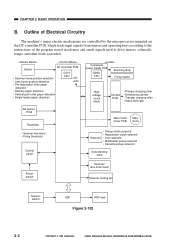
...Transfer charging roller • Static eliminator AE sensor PCB Thermistor • Scanner thermistor • Fixing thermistor Control panel Main motor Main driver PCB motor Solenoid • Pickup clutch solenoid • Registration clutch solenoid • Lens solenoid • Multifeeder pickup solenoid •...switch Scanner/ lens drive motor Scanner cooling fan Sensor/ switch ADF ADF load Figure 2-102 2-2 COPYRIGHT © 1999 CANON INC. Outline of Electrical Circuitry The machine's major electric mechanisms are controlled by the microprocessor mounted on the DC controller ...
...Transfer charging roller • Static eliminator AE sensor PCB Thermistor • Scanner thermistor • Fixing thermistor Control panel Main motor Main driver PCB motor Solenoid • Pickup clutch solenoid • Registration clutch solenoid • Lens solenoid • Multifeeder pickup solenoid •...switch Scanner/ lens drive motor Scanner cooling fan Sensor/ switch ADF ADF load Figure 2-102 2-2 COPYRIGHT © 1999 CANON INC. Outline of Electrical Circuitry The machine's major electric mechanisms are controlled by the microprocessor mounted on the DC controller ...
Service Manual
Page 42
Rotating the Main Motor at the same time, indicate 'E010' in the display. 2-6 COPYRIGHT © 1999 CANON INC. The main motor driver PCB sends the constant speed state signal (MLOCK=0) to rotate the main motor (M1). If the signal remains '1' for about 1 sec, the DC controller will ... the rotation of the reference signals match. When the main motor drive signal (MMD) from the DC controller circuit goes '1', the main motor driver turns on the motor driver PCB controls the main motor so that the phase of the frequency of the clock pulse signals (MMCLK) occurring when the motor rotates...
Rotating the Main Motor at the same time, indicate 'E010' in the display. 2-6 COPYRIGHT © 1999 CANON INC. The main motor driver PCB sends the constant speed state signal (MLOCK=0) to rotate the main motor (M1). If the signal remains '1' for about 1 sec, the DC controller will ... the rotation of the reference signals match. When the main motor drive signal (MMD) from the DC controller circuit goes '1', the main motor driver turns on the motor driver PCB controls the main motor so that the phase of the frequency of the clock pulse signals (MMCLK) occurring when the motor rotates...
Service Manual
Page 45
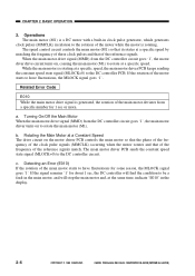
CANON PC800s/900s REV.0 AUG. 1999 PRINTED IN JAPAN (IMPRIME AU JAPON) 2-9 CHAPTER 2 BASIC OPERATION 3. Outputs from the DC Controller (1/2) Line filter LF1 J201-2 (220/240V ... '0', the fixing heater turns on. M2 Scanner/ lens drive motor Figure 2-107 See p. 3-7. COPYRIGHT © 1999 CANON INC. Primary charging roller Developing cylinder Transfer charging roller Static eliminator HVT board M1 Main motor Main motor driver PCB Highvoltage circuit block +24V Microprocessor Communication with the composite power supply J103-6 MMD J104-1 MLOCK...
CANON PC800s/900s REV.0 AUG. 1999 PRINTED IN JAPAN (IMPRIME AU JAPON) 2-9 CHAPTER 2 BASIC OPERATION 3. Outputs from the DC Controller (1/2) Line filter LF1 J201-2 (220/240V ... '0', the fixing heater turns on. M2 Scanner/ lens drive motor Figure 2-107 See p. 3-7. COPYRIGHT © 1999 CANON INC. Primary charging roller Developing cylinder Transfer charging roller Static eliminator HVT board M1 Main motor Main motor driver PCB Highvoltage circuit block +24V Microprocessor Communication with the composite power supply J103-6 MMD J104-1 MLOCK...
Service Manual
Page 54
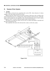
... home position signal (SCHP) Scanner home position sensor (PS1) J110-1 -2 -3 -4 -5 -6 J101-1 Figure 3-104 Q109 Motor driver circuit DC controller PCB 3-4 COPYRIGHT © 1999 CANON INC. Outline The scanner is moved varies according to the length of rotation changes to the selected reproduction ratio on a continuous basis...; CANON PC800s/900s REV.0 AUG. 1999 PRINTED IN JAPAN (IMPRIME AU JAPON) The scanner/lens drive motor dives the lens drive...
... home position signal (SCHP) Scanner home position sensor (PS1) J110-1 -2 -3 -4 -5 -6 J101-1 Figure 3-104 Q109 Motor driver circuit DC controller PCB 3-4 COPYRIGHT © 1999 CANON INC. Outline The scanner is moved varies according to the length of rotation changes to the selected reproduction ratio on a continuous basis...; CANON PC800s/900s REV.0 AUG. 1999 PRINTED IN JAPAN (IMPRIME AU JAPON) The scanner/lens drive motor dives the lens drive...
Service Manual
Page 57
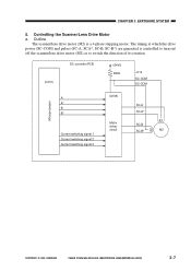
... Drive Motor a. The timing at which the drive power (SC-COM) and pulses (SC-A, SCA*, SC-B, SC-B*) are generated is a 4-phase stepping motor. CANON PC800s/900s REV.0 AUG. 1999 PRINTED IN JAPAN (IMPRIME AU JAPON) 3-7 Outline The scanner/lens drive motor (M2) is controlled to turn on/ off the...rotation. (Q101) DC controller PCB +24VU R399 J110 SC-COM SC-COM Microprocessor A A* B B* Current switching signal 1 Current switching signal 2 Current switching signal 3 (Q109) Motor driver circuit SC-A SC-A* SC-B SC-B* M2 COPYRIGHT © 1999 CANON INC. CHAPTER 3 EXPOSURE SYSTEM 5.
... Drive Motor a. The timing at which the drive power (SC-COM) and pulses (SC-A, SCA*, SC-B, SC-B*) are generated is a 4-phase stepping motor. CANON PC800s/900s REV.0 AUG. 1999 PRINTED IN JAPAN (IMPRIME AU JAPON) 3-7 Outline The scanner/lens drive motor (M2) is controlled to turn on/ off the...rotation. (Q101) DC controller PCB +24VU R399 J110 SC-COM SC-COM Microprocessor A A* B B* Current switching signal 1 Current switching signal 2 Current switching signal 3 (Q109) Motor driver circuit SC-A SC-A* SC-B SC-B* M2 COPYRIGHT © 1999 CANON INC. CHAPTER 3 EXPOSURE SYSTEM 5.

Service Manual
Page 58
...reproduction ratio). Caution: The fuse (R339) will blow to cut the power to the scanner/lens drive motor (M2) through the motor driver circuit. CHAPTER 3 EXPOSURE SYSTEM b. In response, it applies drive pulses to the motor. Any of its rotation according to 3 generated by the...generated by the microprocessor (Q101) are used to control the current flowing to the motor so that it has blown. 3-8 COPYRIGHT © 1999 CANON INC. Operations The microprocessor (Q101) mounted on and off by pulse signals (A through SC-B*). The scanner motor is a 4-phase stepping motor, and...
...reproduction ratio). Caution: The fuse (R339) will blow to cut the power to the scanner/lens drive motor (M2) through the motor driver circuit. CHAPTER 3 EXPOSURE SYSTEM b. In response, it applies drive pulses to the motor. Any of its rotation according to 3 generated by the...generated by the microprocessor (Q101) are used to control the current flowing to the motor so that it has blown. 3-8 COPYRIGHT © 1999 CANON INC. Operations The microprocessor (Q101) mounted on and off by pulse signals (A through SC-B*). The scanner motor is a 4-phase stepping motor, and...

Service Manual
Page 183
... motor (M2) +24VU Scanner cooling fan +24VU Blanking lamp +24VU Main motor/ main motor M1 driver PCB Fixing heater Scanning lamp Primary charging roller Developing roller Transfer roller Static eliminator Figure 7-201 COPYRIGHT © 1999 CANON INC. CANON PC800s/900s REV.0 AUG. 1999 PRINTED IN JAPAN (IMPRIME AU JAPON) 7-3 CHAPTER 7 EXTERNALS/AUXILIARY MECHANISMS...
... motor (M2) +24VU Scanner cooling fan +24VU Blanking lamp +24VU Main motor/ main motor M1 driver PCB Fixing heater Scanning lamp Primary charging roller Developing roller Transfer roller Static eliminator Figure 7-201 COPYRIGHT © 1999 CANON INC. CANON PC800s/900s REV.0 AUG. 1999 PRINTED IN JAPAN (IMPRIME AU JAPON) 7-3 CHAPTER 7 EXTERNALS/AUXILIARY MECHANISMS...
Service Manual
Page 220
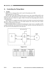
... the pickup motor cannot rotate as controlled, possibly leading to the combinations of the states of the control circuit for each combination.) The motor driver is a DC motor. The CPU (Q1) on the copier and stop the pickup motor at the same time. CHAPTER 8 ADF G. ...24V Q1 CPU PM1 PM0 Q5 Motor driver PMRD1 PMRD1* Pickup motor M2 Figure 8-121 Motor drive signal (PM0) '1' '1' '0' '0' Motor drive signal (PM1) '1' '0' '1' '0' Table 8-102 Pickup roller rotation Braked Picking up Delivering At reset (free) 8-14 COPYRIGHT © 1999 CANON INC. Any pickup fault causes the ADF...
... the pickup motor cannot rotate as controlled, possibly leading to the combinations of the states of the control circuit for each combination.) The motor driver is a DC motor. The CPU (Q1) on the copier and stop the pickup motor at the same time. CHAPTER 8 ADF G. ...24V Q1 CPU PM1 PM0 Q5 Motor driver PMRD1 PMRD1* Pickup motor M2 Figure 8-121 Motor drive signal (PM0) '1' '1' '0' '0' Motor drive signal (PM1) '1' '0' '1' '0' Table 8-102 Pickup roller rotation Braked Picking up Delivering At reset (free) 8-14 COPYRIGHT © 1999 CANON INC. Any pickup fault causes the ADF...

Service Manual
Page 221
...a 4-phase control stepping motor. CANON PC800s/900s REV.0 AUG. 1999 PRINTED IN JAPAN (IMPRIME AU JAPON) 8-15 The CPU (Q1) on the controller and stop the belt motor at the same time. Any feeding fault will not flow. In response, the motor driver changes the output timing of the ... will cause the ADF controller to flash the Jam indicator on the ADF controller PCB sends control pulse signals (A, A*, B, B*) to the motor driver (Q4). If loads large enough to activate the limiter function occur in succession, the belt motor cannot rotate as specified, possibly leading to rotate ...
...a 4-phase control stepping motor. CANON PC800s/900s REV.0 AUG. 1999 PRINTED IN JAPAN (IMPRIME AU JAPON) 8-15 The CPU (Q1) on the controller and stop the belt motor at the same time. Any feeding fault will not flow. In response, the motor driver changes the output timing of the ... will cause the ADF controller to flash the Jam indicator on the ADF controller PCB sends control pulse signals (A, A*, B, B*) to the motor driver (Q4). If loads large enough to activate the limiter function occur in succession, the belt motor cannot rotate as specified, possibly leading to rotate ...

Service Manual
Page 328
...to turn on." Correct the connection and wiring of J205 on the fixing heater side? COPYRIGHT © 1999 CANON INC. Is the problem corrected? 4 Replace the composite power supply PCB. Is the wiring from the composite ...2 Is there electrical continuity between J901-1 (+) and -2 (-) on the power switch. Replace the main motor (M1). YES End. CANON PC800s/900s REV.0 AUG. 1999 PRINTED IN JAPAN (IMPRIME AU JAPON) 11-63 Thermistor (TH1) Composite power supply PCB DC controller... connection of the connectors. Check the wiring from the main motor driver PCB to the main motor (M1).
...to turn on." Correct the connection and wiring of J205 on the fixing heater side? COPYRIGHT © 1999 CANON INC. Is the problem corrected? 4 Replace the composite power supply PCB. Is the wiring from the composite ...2 Is there electrical continuity between J901-1 (+) and -2 (-) on the power switch. Replace the main motor (M1). YES End. CANON PC800s/900s REV.0 AUG. 1999 PRINTED IN JAPAN (IMPRIME AU JAPON) 11-63 Thermistor (TH1) Composite power supply PCB DC controller... connection of the connectors. Check the wiring from the main motor driver PCB to the main motor (M1).
Service Manual
Page 333
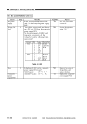
motor 3 GND driver 4 24V PCB Action See "AC power fails to 30 VDC, and turn ... - Cause AC power supply Wiring, DC load Step 1 2 Checks Is AC power present between the following terminals normal? CANON PC800s/900s REV.0 AUG. 1999 PRINTED IN JAPAN (IMPRIME AU JAPON) YES/NO NO YES Connector Pin Output Remarks J202 1...5V PCB 4 5V 5 GND 6 24V J205 1 - NO Replace the composite power supply PCB. 11-68 11-68 COPYRIGHT © 1999 CANON INC. CHAPTER 11 TROUBLESHOOTING 15 DC power fails to turn on the composite power supply PCB blown? 120V model: 125 V, 5 V 220/240V...
motor 3 GND driver 4 24V PCB Action See "AC power fails to 30 VDC, and turn ... - Cause AC power supply Wiring, DC load Step 1 2 Checks Is AC power present between the following terminals normal? CANON PC800s/900s REV.0 AUG. 1999 PRINTED IN JAPAN (IMPRIME AU JAPON) YES/NO NO YES Connector Pin Output Remarks J202 1...5V PCB 4 5V 5 GND 6 24V J205 1 - NO Replace the composite power supply PCB. 11-68 11-68 COPYRIGHT © 1999 CANON INC. CHAPTER 11 TROUBLESHOOTING 15 DC power fails to turn on the composite power supply PCB blown? 120V model: 125 V, 5 V 220/240V...
Service Manual
Page 360
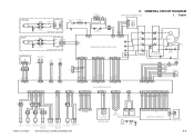
...Single-feeder position sensor paper sensor (Single-feeder type only) SL5 Cassette pickup solenoid PS4 Vertical path roller paper sensor COPYRIGHT © 1999 CANON INC. CANON PC800s/900s REV.0 AUG. 1999 PRINTED IN JAPAN (IMPRIME AU JAPON) J751 3 2 1 Q751 Pre-registration roller paper sensor SENSOR ...16 17 18 19 J301 2 1 J302 CONTROL PANEL PCB J3 VZ1 J4 Fixing film Varistor 1 1 2 J303 Power switch A-5 GENERAL CIRCUIT DIAGRAM MAIN MOTOR DRIVER PCB 1. [220/240V] H N Line filter J502 J501 FT2 FT4 LF1 2 2 FT1 FT3 1 1 J1 DS1 Door switch NF1 NOISE FILTER PCB Thermal...
...Single-feeder position sensor paper sensor (Single-feeder type only) SL5 Cassette pickup solenoid PS4 Vertical path roller paper sensor COPYRIGHT © 1999 CANON INC. CANON PC800s/900s REV.0 AUG. 1999 PRINTED IN JAPAN (IMPRIME AU JAPON) J751 3 2 1 Q751 Pre-registration roller paper sensor SENSOR ...16 17 18 19 J301 2 1 J302 CONTROL PANEL PCB J3 VZ1 J4 Fixing film Varistor 1 1 2 J303 Power switch A-5 GENERAL CIRCUIT DIAGRAM MAIN MOTOR DRIVER PCB 1. [220/240V] H N Line filter J502 J501 FT2 FT4 LF1 2 2 FT1 FT3 1 1 J1 DS1 Door switch NF1 NOISE FILTER PCB Thermal...


