
Product Information - English
Page 1
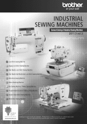
Please find our office to inquire on outside back cover. General Catalog of Industrial Sewing Machines 2011.3 vol.3 Lock Stitch Sewing Machine Zigzag Lock Stitch Sewing Machine Twin Needle Lock Stitch Sewing Machine Twin Needle Split Needle Bar Lock Stitch Sewing Machine Buttonhole Sewing Machine Button Attaching Machine Bar Tacking Machine / Pattern Tacking Machine Programmable Electronic Pattern Sewing Machine Double Chain Stitch Sewing Machine Blind Stitch Sewing Machine Catalogs of each model are available. Visit our official site http://www.brother.com/ for further information.
Please find our office to inquire on outside back cover. General Catalog of Industrial Sewing Machines 2011.3 vol.3 Lock Stitch Sewing Machine Zigzag Lock Stitch Sewing Machine Twin Needle Lock Stitch Sewing Machine Twin Needle Split Needle Bar Lock Stitch Sewing Machine Buttonhole Sewing Machine Button Attaching Machine Bar Tacking Machine / Pattern Tacking Machine Programmable Electronic Pattern Sewing Machine Double Chain Stitch Sewing Machine Blind Stitch Sewing Machine Catalogs of each model are available. Visit our official site http://www.brother.com/ for further information.
Product Information - English
Page 3
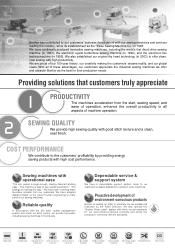
...'s first direct-drive sewing machine (in 1993), the electronic eyelet buttonhole sewing machine (in 1994), and the electronic bar tacking machine (in 2003) to offer clean, neat sewing with operational ease "The arm pocket is large enough, making material handling easy." Drop feed Needle feed Adjustable top and Double horizontal hook Triple horizontal hook bottom feed (vertical axis) (vertical axis) Light-weight materials Medium-weight materials Heavy-weight Extra heavy-weight Thread trimmer materials...
...'s first direct-drive sewing machine (in 1993), the electronic eyelet buttonhole sewing machine (in 1994), and the electronic bar tacking machine (in 2003) to offer clean, neat sewing with operational ease "The arm pocket is large enough, making material handling easy." Drop feed Needle feed Adjustable top and Double horizontal hook Triple horizontal hook bottom feed (vertical axis) (vertical axis) Light-weight materials Medium-weight materials Heavy-weight Extra heavy-weight Thread trimmer materials...
Product Information - English
Page 8
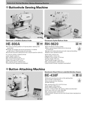
.... sewing speed: 4,000 sti/min Thread trimmer equipped as desired. Stitch pitch: 0.5-2.0 mm Zigzag width: 1.5-5.0 mm Height of presser foot: 13 mm Max. sewing width: 6 mm Max. button hole length: 40 mm Height of work clamp: 12-16 mm Sewing length: 5-50 mm Taper bartack length: 0-20 mm Max. Buttonhole Sewing Machine / Button Attaching Machine Buttonhole Sewing Machine HE-800A Electronic Lockstitch Button Holer HE-800A •21 built-in sewing patterns. Quick and accurate cutting driven by a double position solenoid...
.... sewing speed: 4,000 sti/min Thread trimmer equipped as desired. Stitch pitch: 0.5-2.0 mm Zigzag width: 1.5-5.0 mm Height of presser foot: 13 mm Max. sewing width: 6 mm Max. button hole length: 40 mm Height of work clamp: 12-16 mm Sewing length: 5-50 mm Taper bartack length: 0-20 mm Max. Buttonhole Sewing Machine / Button Attaching Machine Buttonhole Sewing Machine HE-800A Electronic Lockstitch Button Holer HE-800A •21 built-in sewing patterns. Quick and accurate cutting driven by a double position solenoid...
Product Information - English
Page 9
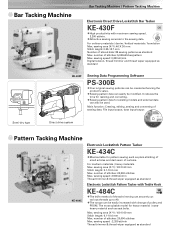
... Bar Tacker KE-430F •High productivity with Treble Hook KE-484C •The knife method of pulley and PROM. File input/output, data input/output Semi-dry type Direct drive system Pattern Tacking Machine KE-484C Electronic Lockstitch Pattern Tacker KE-434C •Most suitable for existing models and external data can be created enhancing the •product's value. sewing area (X-Y): 100 X 60 mm Stitch length...
... Bar Tacker KE-430F •High productivity with Treble Hook KE-484C •The knife method of pulley and PROM. File input/output, data input/output Semi-dry type Direct drive system Pattern Tacking Machine KE-484C Electronic Lockstitch Pattern Tacker KE-434C •Most suitable for existing models and external data can be created enhancing the •product's value. sewing area (X-Y): 100 X 60 mm Stitch length...

Parts Manual - English
Page 3
.... Accessories 53 Z2. Feed mechanism 9 C2. Tension release mechanism 29 M. Power supply equipment mechanism. 45 T. Attachment set (Option parts) 59 Sp. Upper shaft and needle bar mechanism 3 B2. Rotary hook mechanism 17 G. Synchronizer 33 P. Foot switch pedal mechanism (Option parts) 51 Z1. Operation panel mechanism 47 U. Cc:intro' box mechanism 39 R. Accessories 57 AA1. Bobbin winder mechanism 23 K. Warning labels 63 Index 64 Notes for using this parts book 1 This book was...
.... Accessories 53 Z2. Feed mechanism 9 C2. Tension release mechanism 29 M. Power supply equipment mechanism. 45 T. Attachment set (Option parts) 59 Sp. Upper shaft and needle bar mechanism 3 B2. Rotary hook mechanism 17 G. Synchronizer 33 P. Foot switch pedal mechanism (Option parts) 51 Z1. Operation panel mechanism 47 U. Cc:intro' box mechanism 39 R. Accessories 57 AA1. Bobbin winder mechanism 23 K. Warning labels 63 Index 64 Notes for using this parts book 1 This book was...
Instruction Manual - English
Page 4
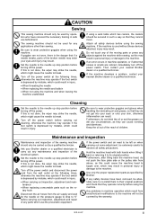
... and diarrhoea. KE-484C iii Set the needle to the needle up stop position before turning off the power switch at the following times, otherwise the machine may operate if the foot switch is not done, the wiper may result. Turn off the power. Ask your eyes and injury may strike the needle, which might cause the needle to break. Turn off the power switch. If...
... and diarrhoea. KE-484C iii Set the needle to the needle up stop position before turning off the power switch at the following times, otherwise the machine may operate if the foot switch is not done, the wiper may result. Turn off the power. Ask your eyes and injury may strike the needle, which might cause the needle to break. Turn off the power switch. If...
Instruction Manual - English
Page 6
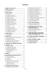
...-1. TABLE OF ERROR CODES 56 16. Checking the needle 31 9-2. STANDARD ADJUSTMENTS 34 10-1. SPECIFICATIONS 2 2-1. Installing the rubber cushions 5 3-4. Installing the switching plate 6 3-7. Operating procedure 21 5-3. Adjusting the work clamp 55 15. USING THE COUNTERS 44 11-1. Using user programs 47 13. CORRECT USE 25 7-1. Threading the upper thread 25 7-3. Cleaning the control box air inlet port 33 9-6. Cleaning the eye guard 33 10. Installing the machine head 6 3-8. Connecting the cords 9 3-12. Piping 12 3-13. Installing the needle...
...-1. TABLE OF ERROR CODES 56 16. Checking the needle 31 9-2. STANDARD ADJUSTMENTS 34 10-1. SPECIFICATIONS 2 2-1. Installing the rubber cushions 5 3-4. Installing the switching plate 6 3-7. Operating procedure 21 5-3. Adjusting the work clamp 55 15. USING THE COUNTERS 44 11-1. Using user programs 47 13. CORRECT USE 25 7-1. Threading the upper thread 25 7-3. Cleaning the control box air inlet port 33 9-6. Cleaning the eye guard 33 10. Installing the machine head 6 3-8. Connecting the cords 9 3-12. Piping 12 3-13. Installing the needle...

Instruction Manual - English
Page 7
1. NAME OF EACH PART 3157Q 3212Q (1) Power switch (2) Control box (3) Operation panel (4) Foot switch (5) Motor (6) EMERGENCY STOP switch (7) Pulley (8) Spool stand (9) Thread take-up lever (10) Thread wiper switch Safety devices; (11) Finger guard (12) Eye guard (13) Thread take-up cover (14) Belt cover (15) Frame side cover 1 KE-484C NAME OF EACH PART 1.
1. NAME OF EACH PART 3157Q 3212Q (1) Power switch (2) Control box (3) Operation panel (4) Foot switch (5) Motor (6) EMERGENCY STOP switch (7) Pulley (8) Spool stand (9) Thread take-up lever (10) Thread wiper switch Safety devices; (11) Finger guard (12) Eye guard (13) Thread take-up cover (14) Belt cover (15) Frame side cover 1 KE-484C NAME OF EACH PART 1.
Instruction Manual - English
Page 8
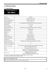
.... KE-484C 2 Feed mechanism R-θ intermittent feed mechanism (pulse-motor driven mechanism) Stitch length 0.1 - 10.0 mm Number of stitches (15 stitches or less) is within 10,000. SPECIFICATIONS Main use Seat Belt Stitch formation Single needle lock stitch Maximum sewing speed 2,200 rpm (Pitch 3 mm) Maximum pattern size 100 × 60 mm max. 2. SPECIFICATIONS 2-1. Consult with a small number of stitches Variable Maximum stitch number 20,000 stitches (including 10,000 stitches which can be added) Work clamp lifter Pneumatic type Work clamp...
.... KE-484C 2 Feed mechanism R-θ intermittent feed mechanism (pulse-motor driven mechanism) Stitch length 0.1 - 10.0 mm Number of stitches (15 stitches or less) is within 10,000. SPECIFICATIONS Main use Seat Belt Stitch formation Single needle lock stitch Maximum sewing speed 2,200 rpm (Pitch 3 mm) Maximum pattern size 100 × 60 mm max. 2. SPECIFICATIONS 2-1. Consult with a small number of stitches Variable Maximum stitch number 20,000 stitches (including 10,000 stitches which can be added) Work clamp lifter Pneumatic type Work clamp...

Instruction Manual - English
Page 10
... with the three staples (10). INSTALLATION 3-2. board mounting plate (3) will be used with the screws (1). * The main P.C. 3. Secure the power switch cord with the screw (1). 4. Remove the 12 screws (1), and then open the covers (panel mounting assembly (2) and main P.C. KE-484C 4 board mounting plate (3)), and tighten them with control boxes which have the IM sticker attached.) Spacers Flat washers Nuts 2454Q 1. Installing the control box Check that it securely...
... with the three staples (10). INSTALLATION 3-2. board mounting plate (3) will be used with the screws (1). * The main P.C. 3. Secure the power switch cord with the screw (1). 4. Remove the 12 screws (1), and then open the covers (panel mounting assembly (2) and main P.C. KE-484C 4 board mounting plate (3)), and tighten them with control boxes which have the IM sticker attached.) Spacers Flat washers Nuts 2454Q 1. Installing the control box Check that it securely...

Instruction Manual - English
Page 21
... the screw (2) of the control box (1). 2. If foot switch support plate B (13) is not necessary to operate incorrectly. 15 KE-484C Insert the connector of the foot switch (3) into the connector (2) of the upper cover (1). 2. Note: If using the foot switch without installing it can be used in a back-to-front position, it to the work table leg, move the foot switch at this time. * It is used as shown in the direction...
... the screw (2) of the control box (1). 2. If foot switch support plate B (13) is not necessary to operate incorrectly. 15 KE-484C Insert the connector of the foot switch (3) into the connector (2) of the upper cover (1). 2. Note: If using the foot switch without installing it can be used in a back-to-front position, it to the work table leg, move the foot switch at this time. * It is used as shown in the direction...
Instruction Manual - English
Page 27
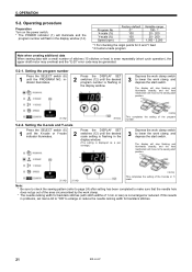
... window (14). Operating procedure Preparation Turn on the power switch. * The POWER indicator (1) will illuminate and the program number will flash in problems, set memo-0d to "ON" to lower the work clamp, and depress the start position. 2516Q 2602Q 5-2-2. Depress the work clamp switch 3 to enlarge or reduce the needle racking width for backtack stitches. 21 KE-484C Note: * Be sure to check the sewing pattern (refer to...
... window (14). Operating procedure Preparation Turn on the power switch. * The POWER indicator (1) will illuminate and the program number will flash in problems, set memo-0d to "ON" to lower the work clamp, and depress the start position. 2516Q 2602Q 5-2-2. Depress the work clamp switch 3 to enlarge or reduce the needle racking width for backtack stitches. 21 KE-484C Note: * Be sure to check the sewing pattern (refer to...

Instruction Manual - English
Page 29
... off the power switch before operating the thread wiper switch. Operating the emergency stop switch If the emergency stop 1. Press the TEST switch (4) once more so that the display panel flashes. 5. Once the work clamp may obstruct the thread wiper. 3169Q 23 KE-484C Turn the pulley by hand to set the needle to the desired position, depress the start switch. Press the BOBBIN.
... off the power switch before operating the thread wiper switch. Operating the emergency stop switch If the emergency stop 1. Press the TEST switch (4) once more so that the display panel flashes. 5. Once the work clamp may obstruct the thread wiper. 3169Q 23 KE-484C Turn the pulley by hand to set the needle to the desired position, depress the start switch. Press the BOBBIN.

Instruction Manual - English
Page 32
... POWER indicator on as shown in B, turn the bobbin winder thread tension stud (8) clockwise; WIND switch (4) after a set screw (6) and pull the bobbin presser (1) outward. The bobbin presser (1) will illuminate.) 4. Case A 3180Q KE-484C Case B 3181Q 26 CORRECT USE 7-3. Winding the lower thread CAUTION Do not touch any objects against the machine while winding the lower thread, as this may result in personal injury or damage to its original position after the machine starts operating. Depress the work clamp switch...
... POWER indicator on as shown in B, turn the bobbin winder thread tension stud (8) clockwise; WIND switch (4) after a set screw (6) and pull the bobbin presser (1) outward. The bobbin presser (1) will illuminate.) 4. Case A 3180Q KE-484C Case B 3181Q 26 CORRECT USE 7-3. Winding the lower thread CAUTION Do not touch any objects against the machine while winding the lower thread, as this may result in personal injury or damage to its original position after the machine starts operating. Depress the work clamp switch...

Instruction Manual - English
Page 50
... set the number of sewing a pattern. 1. Replace the bobbin, and then press the RESET switch (4). * The alarm will then be set the production counter to be sewn. • The bobbin thread counter can be displayed in the display window (6) will not operate during this time, even if the foot switch is depressed, the sewing machine will switch to showing the bobbin thread counter. 11. If you use the bobbin thread...
... set the number of sewing a pattern. 1. Replace the bobbin, and then press the RESET switch (4). * The alarm will then be set the production counter to be sewn. • The bobbin thread counter can be displayed in the display window (6) will not operate during this time, even if the foot switch is depressed, the sewing machine will switch to showing the bobbin thread counter. 11. If you use the bobbin thread...

Instruction Manual - English
Page 55
... left of the display window (4) to the corresponding number (00 to their initial settings (factory default settings). 5. When the BOBBIN. WIND switch (3) is finished, the work clamp automatically opens and closes once (practice operation). ---- : OFF 49 KE-484C " to normal. Feed will move to the sewing start point, and then will return to "ON". * If you press the RESET switch (6) at the right in the display...
... left of the display window (4) to the corresponding number (00 to their initial settings (factory default settings). 5. When the BOBBIN. WIND switch (3) is finished, the work clamp automatically opens and closes once (practice operation). ---- : OFF 49 KE-484C " to normal. Feed will move to the sewing start point, and then will return to "ON". * If you press the RESET switch (6) at the right in the display...

Instruction Manual - English
Page 62
... power, and then return the machine head to its original position. E-13 Machine specification select connector is raised. disconnected. Turn off the power and check if connectors P3 is being continually pressed, or emergency switch connection error. Clearing all memory not match the setting of thread. Needle bar does not stop switch was pressed during sewing. E-67 Thread wiper cylinder does not operate. KE-484C 56 Code...
... power, and then return the machine head to its original position. E-13 Machine specification select connector is raised. disconnected. Turn off the power and check if connectors P3 is being continually pressed, or emergency switch connection error. Clearing all memory not match the setting of thread. Needle bar does not stop switch was pressed during sewing. E-67 Thread wiper cylinder does not operate. KE-484C 56 Code...

Instruction Manual - English
Page 64
... the machine will operate if the foot switch is incorrect. Problem Cause Check Remedy Work clamp does not rise. Bobbin winder thread tension stud height is depressed by mistake, which could result in injury. occur" occur" Uneven length. Incorrect position of needle plate. comes Stitches being skipped at Refer to "Skipped stitches Refer to one side. Thread wiper does not operate correctly. Adjust the work clamp. Thread unthreaded. TROUBLESHOOTING 16. Lower thread winds to "Skipped stitches the sewing start. Bobbin presser position is...
... the machine will operate if the foot switch is incorrect. Problem Cause Check Remedy Work clamp does not rise. Bobbin winder thread tension stud height is depressed by mistake, which could result in injury. occur" occur" Uneven length. Incorrect position of needle plate. comes Stitches being skipped at Refer to "Skipped stitches Refer to one side. Thread wiper does not operate correctly. Adjust the work clamp. Thread unthreaded. TROUBLESHOOTING 16. Lower thread winds to "Skipped stitches the sewing start. Bobbin presser position is...

Instruction Manual - English
Page 65
... hook. 16. TROUBLESHOOTING Problem Cause Check Remedy Upper thread breaks. Upper thread tension is bent. Upper thread tension Adjust the upper thread tension. Needle direction Install the needle correctly. Thread and needle Use the correct thread for the material. 59 KE-484C Thread take -up spring tension and height are incorrect. File smooth or replace the affected part. Lower thread tension Adjust the lower thread tension. Damage Needle clearance Needle bar lift amount File smooth or replace the needle hole plate. Thread stroke take-up lever...
... hook. 16. TROUBLESHOOTING Problem Cause Check Remedy Upper thread breaks. Upper thread tension is bent. Upper thread tension Adjust the upper thread tension. Needle direction Install the needle correctly. Thread and needle Use the correct thread for the material. 59 KE-484C Thread take -up spring tension and height are incorrect. File smooth or replace the affected part. Lower thread tension Adjust the lower thread tension. Damage Needle clearance Needle bar lift amount File smooth or replace the needle hole plate. Thread stroke take-up lever...

Instruction Manual - English
Page 66
...6 KE-484C 60 TROUBLESHOOTING Problem Cause Check Remedy Upper thread is blunt. Fixed knife is not trimmed. Incorrect needle and rotary hook timing. thread Upper thread tension is Replace the head posi- Movable knife position Adjust the position of the switching plate. Thread take -up spring tension and height Head position switch cord connection Switching plate position Adjust the lower thread tension. Adjust the tension and height of the thread takeup spring. Upper thread tension Upper thread length Adjust the upper thread tension. Head position...
...6 KE-484C 60 TROUBLESHOOTING Problem Cause Check Remedy Upper thread is blunt. Fixed knife is not trimmed. Incorrect needle and rotary hook timing. thread Upper thread tension is Replace the head posi- Movable knife position Adjust the position of the switching plate. Thread take -up spring tension and height Head position switch cord connection Switching plate position Adjust the lower thread tension. Adjust the tension and height of the thread takeup spring. Upper thread tension Upper thread length Adjust the upper thread tension. Head position...


