Service Manual
Page 5
... of the paper from the manual feed slot 2-12 5. CONTROL PANEL OPERATION 2-13 5.1 Ready (Paper) LED Indications 2-13 5.2 Data (Toner) LED Indications 2-14 5.3 Drum LED Indications ...2-14 5.4 Alarm LED Indications ...2-14 5.5 Control Panel Button Operations 2-15 5.6 Other Control Features... Functions ...2-18 6.2.1 LED functions...2-18 6.2.2 Factory default setting...2-18 CHAPTER 3 THEORY OF OPERATION 3-1 1. NETWORK BOARD OPERATION (FOR HL-1270N ONLY 2-17 6.1 Preparing the BR-net Board 2-17 6.1.1 Connect the Ethernet cable 2-17 6.1.2 Install the BRAdmin32: configuration utility (for...
... of the paper from the manual feed slot 2-12 5. CONTROL PANEL OPERATION 2-13 5.1 Ready (Paper) LED Indications 2-13 5.2 Data (Toner) LED Indications 2-14 5.3 Drum LED Indications ...2-14 5.4 Alarm LED Indications ...2-14 5.5 Control Panel Button Operations 2-15 5.6 Other Control Features... Functions ...2-18 6.2.1 LED functions...2-18 6.2.2 Factory default setting...2-18 CHAPTER 3 THEORY OF OPERATION 3-1 1. NETWORK BOARD OPERATION (FOR HL-1270N ONLY 2-17 6.1 Preparing the BR-net Board 2-17 6.1.1 Connect the Ethernet cable 2-17 6.1.2 Install the BRAdmin32: configuration utility (for...

Service Manual
Page 6
......3-25 2.5 Toner Cartridge...3-25 2.6 Print Process ...3-26 2.6.1 Charging...3-26 2.6.2 Exposure stage...3-26 2.6.3 Developing...3-27 2.6.4 Transfer...3-28 2.6.5 Fixing stage ...3-28 CHAPTER 4 DISASSEMBLY AND RE-ASSEMBLY 4-1 1. SAFETY PRECAUTIONS 4-1 2. DISASSEMBLY PROCEDURE 4-3 3.1 AC Cord...4-3 3.2 Drum Unit...4-3 3.3 Paper Cassette ...4-4 3.4 Network Board (for HL-1270N only 4-10 3.5 Front Cover...4-11 3.6 Top Cover ...4-12 3.7 Main Cover ...4-13 3.8 Laser Unit ...4-15...
......3-25 2.5 Toner Cartridge...3-25 2.6 Print Process ...3-26 2.6.1 Charging...3-26 2.6.2 Exposure stage...3-26 2.6.3 Developing...3-27 2.6.4 Transfer...3-28 2.6.5 Fixing stage ...3-28 CHAPTER 4 DISASSEMBLY AND RE-ASSEMBLY 4-1 1. SAFETY PRECAUTIONS 4-1 2. DISASSEMBLY PROCEDURE 4-3 3.1 AC Cord...4-3 3.2 Drum Unit...4-3 3.3 Paper Cassette ...4-4 3.4 Network Board (for HL-1270N only 4-10 3.5 Front Cover...4-11 3.6 Top Cover ...4-12 3.7 Main Cover ...4-13 3.8 Laser Unit ...4-15...

Service Manual
Page 7
... 2.2 Service Calls ...6-4 3. NETWORK PROBLEM (FOR HL-1270N ONLY 6-45 9.1 Installation Problem ...6-45 9.2 Intermittent Problem...6-46 9.3 TCP/IP Troubleshooting 6-47 9.4 UNIX Troubleshooting...6-47 v PERIODICAL CLEANING 5-5 3.1 Cleaning the Printer Exterior 5-5 3.2 Cleaning the Drum Unit...5-5 3.3 ... Image Defect Examples 6-23 7.2 Troubleshooting Image Defect 6-24 7.3 Location of Grounding Contacts 6-41 7.3.1 Drum unit ...6-41 7.3.2 Printer body & paper cassette 6-41 8. INCORRECT PRINTOUT 6-42 9. MALFUNCTIONS 6-18 7. INTRODUCTION ...6-1 1.1 Initial Check ...6-1 1.2 Warnings...
... 2.2 Service Calls ...6-4 3. NETWORK PROBLEM (FOR HL-1270N ONLY 6-45 9.1 Installation Problem ...6-45 9.2 Intermittent Problem...6-46 9.3 TCP/IP Troubleshooting 6-47 9.4 UNIX Troubleshooting...6-47 v PERIODICAL CLEANING 5-5 3.1 Cleaning the Printer Exterior 5-5 3.2 Cleaning the Drum Unit...5-5 3.3 ... Image Defect Examples 6-23 7.2 Troubleshooting Image Defect 6-24 7.3 Location of Grounding Contacts 6-41 7.3.1 Drum unit ...6-41 7.3.2 Printer body & paper cassette 6-41 8. INCORRECT PRINTOUT 6-42 9. MALFUNCTIONS 6-18 7. INTRODUCTION ...6-1 1.1 Initial Check ...6-1 1.2 Warnings...
Service Manual
Page 13
... Printing Performance and User-Friendly Operation for Windows The dedicated printer driver for graphics with microfine toner and up to 10 pages per minutes (ppm) print speed (A4 or Letter paper). The printer status monitor program can change the settings by sheet so you know... what to choose various printer settings including toner save mode, custom paper size, sleep mode, gray scale adjustment, resolution, water mark and many layout functions. FEATURES This printer has the following features; High Resolution and Fast Print Speed True...
... Printing Performance and User-Friendly Operation for Windows The dedicated printer driver for graphics with microfine toner and up to 10 pages per minutes (ppm) print speed (A4 or Letter paper). The printer status monitor program can change the settings by sheet so you know... what to choose various printer settings including toner save mode, custom paper size, sleep mode, gray scale adjustment, resolution, water mark and many layout functions. FEATURES This printer has the following features; High Resolution and Fast Print Speed True...
Service Manual
Page 14
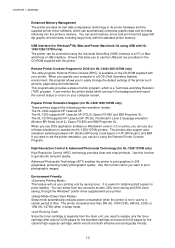
... graphics in 256 grayscales, producing nearly photographic quality. Since the toner cartridge is separate from two economy modes, 25% toner saving and 50% toner saving, through the Windows printer driver supplied with the printer. If you use for the optional high-capacity cartridge, which ...The printer consumes less than 5W (HL-1030/1240), 6W (HL-1250) or 12W (HL-1270N) when in the background and report the current status or errors on the CD-ROM supplied with your printer. The HL-1270N supports HP LaserJet 6P (PCL6), PostScript Level 2 language emulation (Brother BR...
... graphics in 256 grayscales, producing nearly photographic quality. Since the toner cartridge is separate from two economy modes, 25% toner saving and 50% toner saving, through the Windows printer driver supplied with the printer. If you use for the optional high-capacity cartridge, which ...The printer consumes less than 5W (HL-1030/1240), 6W (HL-1250) or 12W (HL-1270N) when in the background and report the current status or errors on the CD-ROM supplied with your printer. The HL-1270N supports HP LaserJet 6P (PCL6), PostScript Level 2 language emulation (Brother BR...
Service Manual
Page 17
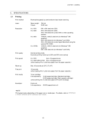
CHAPTER 1 GENERAL 3. SPECIFICATIONS 3.1 Printing Print method Electrophotography by semiconductor laser beam scanning Laser Wave length: 780 nm Output: 5mW max Resolution HL-1030: HL-1240: HL-1250: HL-1270N: 600 x 600 dots/inch (GDI) 600 x 600 dots/inch (GDI) 300 x 300 dots/inch (under DOS or other operating ...15 seconds (when loading A4 or Letter-size paper from the paper cassette.) Warm-up to 25% and 50% toner saving) Print speed HL-1030: Up to 10 pages/minute HL-1240/1250/1270N: Up to APPENDIX 3 'PRINT SPEEDS WITH VARIOUS SETTINGS'. 1-5 For details, refer to 12 pages/...
CHAPTER 1 GENERAL 3. SPECIFICATIONS 3.1 Printing Print method Electrophotography by semiconductor laser beam scanning Laser Wave length: 780 nm Output: 5mW max Resolution HL-1030: HL-1240: HL-1250: HL-1270N: 600 x 600 dots/inch (GDI) 600 x 600 dots/inch (GDI) 300 x 300 dots/inch (under DOS or other operating ...15 seconds (when loading A4 or Letter-size paper from the paper cassette.) Warm-up to 25% and 50% toner saving) Print speed HL-1030: Up to 10 pages/minute HL-1240/1250/1270N: Up to APPENDIX 3 'PRINT SPEEDS WITH VARIOUS SETTINGS'. 1-5 For details, refer to 12 pages/...

Service Manual
Page 26
Printer Paper cassette Drum unit (with Toner cartridge included) Documents CD-ROM Floppy disk Fig. 2-1 NOTE: Components may vary depending on the country. AC cord 2-2 UNPACKING When unpacking the printer, check to see that all of the following components are included in the carton. CHAPTER 2 INSTALLATION AND BASIC OPERATION 2.
Printer Paper cassette Drum unit (with Toner cartridge included) Documents CD-ROM Floppy disk Fig. 2-1 NOTE: Components may vary depending on the country. AC cord 2-2 UNPACKING When unpacking the printer, check to see that all of the following components are included in the carton. CHAPTER 2 INSTALLATION AND BASIC OPERATION 2.
Service Manual
Page 29
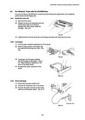
...cover. (2) Unpack the drum unit assembly and rock it from side to side 5 or 6 times to distribute the toner evenly inside the cartridge. (Fig. 2-8) Fig. 2-8 (3) Install the drum unit into the printer until it snaps into place and close the front cover. 3.2.2 Load paper (1) Pull the paper cassette completely out of...) Fig. 2-10 Fig. 2-11 AC power cord 2-5 Check that the power switch is flat placed. (Fig. 210) Paper should be loaded up to the printer. (3) Plug the AC power cord into an AC outlet, then turn on the sliding guide. (4) Re-install the paper cassette into the paper cassette.
...cover. (2) Unpack the drum unit assembly and rock it from side to side 5 or 6 times to distribute the toner evenly inside the cartridge. (Fig. 2-8) Fig. 2-8 (3) Install the drum unit into the printer until it snaps into place and close the front cover. 3.2.2 Load paper (1) Pull the paper cassette completely out of...) Fig. 2-10 Fig. 2-11 AC power cord 2-5 Check that the power switch is flat placed. (Fig. 210) Paper should be loaded up to the printer. (3) Plug the AC power cord into an AC outlet, then turn on the sliding guide. (4) Re-install the paper cassette into the paper cassette.

Service Manual
Page 37
... Paper Alarm Toner Data Control Panel Button Fig. 2-28 5.1 Ready (Paper) LED Indications The Ready LED indicates the current status of the printer lowers. ON The printer is in sleep mode. Error Action Paper jam Clear the paper jam and press the panel button if the printer does not ... as the Paper LED with the Alarm LED. LED Printer status OFF The power switch is off, or the printer is ready to indicate a paper error. If the printer is cooling down and stops printing until the internal temperature of the printer. CONTROL PANEL OPERATION There are four LEDs and a ...
... Paper Alarm Toner Data Control Panel Button Fig. 2-28 5.1 Ready (Paper) LED Indications The Ready LED indicates the current status of the printer lowers. ON The printer is in sleep mode. Error Action Paper jam Clear the paper jam and press the panel button if the printer does not ... as the Paper LED with the Alarm LED. LED Printer status OFF The power switch is off, or the printer is ready to indicate a paper error. If the printer is cooling down and stops printing until the internal temperature of the printer. CONTROL PANEL OPERATION There are four LEDs and a ...

Service Manual
Page 38
...See also Subsection 2.1 'Operator Calls' in CHAPTER 6. 2-14 Purchase a new toner cartridge ready for when the 'Toner empty' error is nearly empty. LED Printer status OFF The printer has no other error occurs, the printer indicates the error by blinking the Alarm LED with the Alarm LED. ON Print... 6 for a long period of its life. Error Action Toner low Indicates that the toner cartridge is indicated. ON The drum unit is recommended to obtain a new drum unit to indicate a printer error status such as the Toner LED with another LED or by printing an error report. ...
...See also Subsection 2.1 'Operator Calls' in CHAPTER 6. 2-14 Purchase a new toner cartridge ready for when the 'Toner empty' error is nearly empty. LED Printer status OFF The printer has no other error occurs, the printer indicates the error by blinking the Alarm LED with the Alarm LED. ON Print... 6 for a long period of its life. Error Action Toner low Indicates that the toner cartridge is indicated. ON The drum unit is recommended to obtain a new drum unit to indicate a printer error status such as the Toner LED with another LED or by printing an error report. ...

Service Manual
Page 43
... Charging block Drum Paper dust cleaner block Developing block Toner cartridge Image generation system Paper tray unit Paper cassette Manual feed Fixing unit Paper eject block Paper feed system Fig. 3-1 3-1 CHAPTER 3 THEORY OF OPERATION CHAPTER3 THEORY OF OPERATION 1. ELECTRONICS 1.1 General Block Diagram HL-1030/1240 Fig. 3-1 shows a general block diagram of the HL-1030/1240 printer.
... Charging block Drum Paper dust cleaner block Developing block Toner cartridge Image generation system Paper tray unit Paper cassette Manual feed Fixing unit Paper eject block Paper feed system Fig. 3-1 3-1 CHAPTER 3 THEORY OF OPERATION CHAPTER3 THEORY OF OPERATION 1. ELECTRONICS 1.1 General Block Diagram HL-1030/1240 Fig. 3-1 shows a general block diagram of the HL-1030/1240 printer.

Service Manual
Page 44
...HL-1250 printer. RS-232C) Expansion I /F board (Mac. External device Optional RAM (SIMM) (max. 32Mbytes) Control system RAM 4MB Expansion memory I/O Optional I /O Video control block Interface block (Parallel / USB) External device Low-voltage power supply block High-voltage power supply block Engine control block Operation block (Control panel) Laser... unit Drive block (DC motor) Drum unit Transfer block Charging block Drum Paper dust cleaner block Developing block Toner cartridge Image generation system Paper tray unit...
...HL-1250 printer. RS-232C) Expansion I /F board (Mac. External device Optional RAM (SIMM) (max. 32Mbytes) Control system RAM 4MB Expansion memory I/O Optional I /O Video control block Interface block (Parallel / USB) External device Low-voltage power supply block High-voltage power supply block Engine control block Operation block (Control panel) Laser... unit Drive block (DC motor) Drum unit Transfer block Charging block Drum Paper dust cleaner block Developing block Toner cartridge Image generation system Paper tray unit...

Service Manual
Page 45
...HL-1270N printer. External device Optional RAM (SIMM) (max. 32Mbytes) Control system RAM 4MB Expansion memory I/O Network board Ethernet 10/100 Base TX PCI bus Video control block Interface block (Parallel / USB) External device Low-voltage power supply block High-voltage power supply block Engine control block Operation block (Control panel) Laser... unit Drive block (DC motor) Drum unit Transfer block Charging block Drum Paper dust cleaner block Developing block Toner cartridge Image generation system Paper tray unit ...
...HL-1270N printer. External device Optional RAM (SIMM) (max. 32Mbytes) Control system RAM 4MB Expansion memory I/O Network board Ethernet 10/100 Base TX PCI bus Video control block Interface block (Parallel / USB) External device Low-voltage power supply block High-voltage power supply block Engine control block Operation block (Control panel) Laser... unit Drive block (DC motor) Drum unit Transfer block Charging block Drum Paper dust cleaner block Developing block Toner cartridge Image generation system Paper tray unit ...

Service Manual
Page 60
...PCB through the RJ-45 connector. The engine PCB controls the following parts by using the transferred signal data; • Main motor • Toner sensor • Panel PCB • Cover sensor • Fan motor • Front registration sensor • Thermistor • Rear registration ...sensor • Polygon motor • Upper paper cassette sensor (HL-1250/1270N only) • Solenoid • Lower paper cassette registration sensor (HL-1250/1270N only) • High-voltage power supply For the circuit diagram of the BR-net PCB...
...PCB through the RJ-45 connector. The engine PCB controls the following parts by using the transferred signal data; • Main motor • Toner sensor • Panel PCB • Cover sensor • Fan motor • Front registration sensor • Thermistor • Rear registration ...sensor • Polygon motor • Upper paper cassette sensor (HL-1250/1270N only) • Solenoid • Lower paper cassette registration sensor (HL-1250/1270N only) • High-voltage power supply For the circuit diagram of the BR-net PCB...

Service Manual
Page 63
CHAPTER 3 THEORY OF OPERATION 2. MECHANICS 2.1 Overview of Printing Mechanism Second eject roller Photosensitive drum Thermistor Cleaner Corona wire Laser Unit Polygon mirror Scanner motor Rear cover Heat roller First eject roller Drum Unit Development roller Blade Agitator Toner sensor Supply roller Paper feed roller Fixing Unit Eject sensor lever Pressure roller Transfer roller Paper pick-up roller Cassette pressure roller Separation pad Paper Pressure plate Paper Cassette Rear registration sensor lever Fig. 3-27 Front registration sensor lever 3-21
CHAPTER 3 THEORY OF OPERATION 2. MECHANICS 2.1 Overview of Printing Mechanism Second eject roller Photosensitive drum Thermistor Cleaner Corona wire Laser Unit Polygon mirror Scanner motor Rear cover Heat roller First eject roller Drum Unit Development roller Blade Agitator Toner sensor Supply roller Paper feed roller Fixing Unit Eject sensor lever Pressure roller Transfer roller Paper pick-up roller Cassette pressure roller Separation pad Paper Pressure plate Paper Cassette Rear registration sensor lever Fig. 3-27 Front registration sensor lever 3-21

Service Manual
Page 64
...Halogen Heater Lamp Laser Unit Laser Polygon Motor Engine PCB Front Registration Sensor Rear Registration Sensor Upper Paper Cassette Sensor (HL-1250/1270N) Lower Paper Cassette Registration Sensor (HL-1250/1270N) ...HighVoltage Power Supply PCB Cover Sensor (B) Drum Unit Primary Charger (Corona Wire) Primary Charger (Grid) Development Roller Supply Roller Transfer Roller Solenoid Fan Motor Main Motor Toner...
...Halogen Heater Lamp Laser Unit Laser Polygon Motor Engine PCB Front Registration Sensor Rear Registration Sensor Upper Paper Cassette Sensor (HL-1250/1270N) Lower Paper Cassette Registration Sensor (HL-1250/1270N) ...HighVoltage Power Supply PCB Cover Sensor (B) Drum Unit Primary Charger (Corona Wire) Primary Charger (Grid) Development Roller Supply Roller Transfer Roller Solenoid Fan Motor Main Motor Toner...

Service Manual
Page 66
... A and B Detect opening and closing of the front cover. The eject sensor lever detects whether the paper is fed to the fixing unit to the printer rear (straight paper path). CHAPTER 3 THEORY OF OPERATION 2.2.3 Paper eject After the printing image on the photosensitive drum is transferred onto the paper, the paper... is ejected correctly or not. Afterwards, the paper is ejected from the first eject roller, the paper is ejected face up straight to fix unfixed toner onto the paper. If the rear cover is open, the paper is turned by the first eject roller in the fixing unit.
... A and B Detect opening and closing of the front cover. The eject sensor lever detects whether the paper is fed to the fixing unit to the printer rear (straight paper path). CHAPTER 3 THEORY OF OPERATION 2.2.3 Paper eject After the printing image on the photosensitive drum is transferred onto the paper, the paper... is ejected correctly or not. Afterwards, the paper is ejected from the first eject roller, the paper is ejected face up straight to fix unfixed toner onto the paper. If the rear cover is open, the paper is turned by the first eject roller in the fixing unit.

Service Manual
Page 67
...surface. (1) Corona wire Generates the ion charge on the drum. (2) Grid Spreads the ion charge evenly over the drum surface. 2.4.3 Transfer roller Transfers the toner image to the paper from the drum surface. 2.4.4 Cleaner Removes the paper dust or dirt on the surface of the... on the left side of the photosensitive drum. 2.5 Toner Cartridge Develops the electrostatic latent image on the photosensitive drum with toner and forms the visible image. 3-25 The toner sensor at the right side receives it when the toner is installed in the toner cartridge. They also detect whether or not the drum...
...surface. (1) Corona wire Generates the ion charge on the drum. (2) Grid Spreads the ion charge evenly over the drum surface. 2.4.3 Transfer roller Transfers the toner image to the paper from the drum surface. 2.4.4 Cleaner Removes the paper dust or dirt on the surface of the... on the left side of the photosensitive drum. 2.5 Toner Cartridge Develops the electrostatic latent image on the photosensitive drum with toner and forms the visible image. 3-25 The toner sensor at the right side receives it when the toner is installed in the toner cartridge. They also detect whether or not the drum...

Service Manual
Page 69
...1 2 3 (a) +420 (b) +200 1 Primary charging 2 Laser beam exposure and developing (a) Unexposed area ( Non image area ) (b) Exposed area ( Image area ) 3 Transfer the image to paper Drum Sleeve 0 Time Fig. 3-36 2.6.3 Developing Developing causes the toner to be attracted to the electrostatic image on the drum surface. The...Corona wire Photosensitive drum Transfer roller Supply roller Fig. 3-37 3-27 The toner is the image to be printed. CHAPTER 3 THEORY OF OPERATION The area exposed to the laser beam is nipped between the drum and the development roller, which is ...
...1 2 3 (a) +420 (b) +200 1 Primary charging 2 Laser beam exposure and developing (a) Unexposed area ( Non image area ) (b) Exposed area ( Image area ) 3 Transfer the image to paper Drum Sleeve 0 Time Fig. 3-36 2.6.3 Developing Developing causes the toner to be attracted to the electrostatic image on the drum surface. The...Corona wire Photosensitive drum Transfer roller Supply roller Fig. 3-37 3-27 The toner is the image to be printed. CHAPTER 3 THEORY OF OPERATION The area exposed to the laser beam is nipped between the drum and the development roller, which is ...

Service Manual
Page 70
...the photo-conductive drum. 2.6.5 Fixing stage The image transferred to the paper. The negative charge applied to the paper causes the positively charged toner to leave the drum, and adhere to the paper by static electricity is cleaned by heat and pressure when passing through the heat roller... voltage changes to the transfer roller. As a result, the image is visible on the paper. (2) Cleaning process of transfer roller If the toner is not transferred onto the paper perfectly it is transferred onto the paper by detecting the surface temperature of the heat roller and turning on...
...the photo-conductive drum. 2.6.5 Fixing stage The image transferred to the paper. The negative charge applied to the paper causes the positively charged toner to leave the drum, and adhere to the paper by static electricity is cleaned by heat and pressure when passing through the heat roller... voltage changes to the transfer roller. As a result, the image is visible on the paper. (2) Cleaning process of transfer roller If the toner is not transferred onto the paper perfectly it is transferred onto the paper by detecting the surface temperature of the heat roller and turning on...


