

Service Manual
Page 2
... lifter bell crank stopper 2 3. Belt 2 OPERATION 3 1. Stitch length 5 6. Needle stop position setting 6 10. Programming 7 12. Rotary hook mechanism 21 5. Needle 4 4. Sewing speed setting 6 8. Presser foot mechanism 21 4. Machine head 2 2. Sewing examples 9 MECHANICAL DESCRIPTIONS 11 1. Feed lock mechanism 11 2. Tension release 18 7. Automatic presser bar lifter (subclasses -900) 19 DISASSEMBLY 20 1. Feed mechanism 23 Threading 4 5. Correction stitching setting 6 11. Thread trimmer mechanism 15 6. Sensor sensitivity...
... lifter bell crank stopper 2 3. Belt 2 OPERATION 3 1. Stitch length 5 6. Needle stop position setting 6 10. Programming 7 12. Rotary hook mechanism 21 5. Needle 4 4. Sewing speed setting 6 8. Presser foot mechanism 21 4. Machine head 2 2. Sewing examples 9 MECHANICAL DESCRIPTIONS 11 1. Feed lock mechanism 11 2. Tension release 18 7. Automatic presser bar lifter (subclasses -900) 19 DISASSEMBLY 20 1. Feed mechanism 23 Threading 4 5. Correction stitching setting 6 11. Thread trimmer mechanism 15 6. Sensor sensitivity...

Service Manual
Page 3
... (B7910) 39 12. Solenoid replacements 43 2. Thread wiper 45 3. Sensor position adjustment (B7910) 41 14. Presser foot mechanism 29 5. Spring installation (B7910) 39 11. Indication adjustment of the distance between the needle hole and the sensor 42 REPLACEMENTS 43 1. Feed mechanism 24 2. Rotary hook position 31 3. Potentiometer adjustment (87910) 38 10. ASSEMBLY 24 1. Synchronizer adjustment 35 7. Photo-cell and reflection sensor replacement (37910) 46 4. Synchronizers 48 GAUGE PART CODE 49 TROUBLESHOOTING GUIDE 53
... (B7910) 39 12. Solenoid replacements 43 2. Thread wiper 45 3. Sensor position adjustment (B7910) 41 14. Presser foot mechanism 29 5. Spring installation (B7910) 39 11. Indication adjustment of the distance between the needle hole and the sensor 42 REPLACEMENTS 43 1. Feed mechanism 24 2. Rotary hook position 31 3. Potentiometer adjustment (87910) 38 10. ASSEMBLY 24 1. Synchronizer adjustment 35 7. Photo-cell and reflection sensor replacement (37910) 46 4. Synchronizers 48 GAUGE PART CODE 49 TROUBLESHOOTING GUIDE 53
Service Manual
Page 4
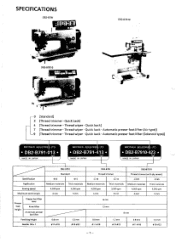
...] 3 [Thread trimmer • Quick back] 4 [Thread trimmer • Thread wiper • Quick back] 7 [Thread trimmer Thread wiper • Quick back • Automatic presser foot lifter (Air type)] -9 [Thread trimmer • Thread wiper • Quick back • Automatic presser foot lifter (Solenoid type)] BROTHER INDUSTRIE LTD. • DB2-B791-013 • MADE IN JAPAN BROTHER INDUSTRI4 LTD. • DB2-B791-413 • MADE IN JAPAN Inv i-I BROTHER INDUSTRIE LTD • DB2-B7910-423 • MADE IN JAPAN Specification Application Sewing speed Maximum stitch length i DB2-8791...
...] 3 [Thread trimmer • Quick back] 4 [Thread trimmer • Thread wiper • Quick back] 7 [Thread trimmer Thread wiper • Quick back • Automatic presser foot lifter (Air type)] -9 [Thread trimmer • Thread wiper • Quick back • Automatic presser foot lifter (Solenoid type)] BROTHER INDUSTRIE LTD. • DB2-B791-013 • MADE IN JAPAN BROTHER INDUSTRI4 LTD. • DB2-B791-413 • MADE IN JAPAN Inv i-I BROTHER INDUSTRIE LTD • DB2-B7910-423 • MADE IN JAPAN Specification Application Sewing speed Maximum stitch length i DB2-8791...

Service Manual
Page 6
To adjust the pressure, turn the presser adjustment screw @. If the oil level falls below the LOW mark, add more oil. (2) If the oil becomes contaminated, remove the oil by turning the oil adjusting screw G. 2. X Use the oil specified by BROTHER: Hi White 70. (4) After removing the face plate, adjust oil absorption by turning the oil regulating valve ©. (5) After tilting the machine head until it stops, adjust oil absorption by removing the oil cover screw 0. (3) Wipe off any...
To adjust the pressure, turn the presser adjustment screw @. If the oil level falls below the LOW mark, add more oil. (2) If the oil becomes contaminated, remove the oil by turning the oil adjusting screw G. 2. X Use the oil specified by BROTHER: Hi White 70. (4) After removing the face plate, adjust oil absorption by turning the oil regulating valve ©. (5) After tilting the machine head until it stops, adjust oil absorption by removing the oil cover screw 0. (3) Wipe off any...
Service Manual
Page 7
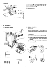
... needle-groove Insert the needle 0 completely, making sure that the long groove of the needle is on the left to the highest position 0 9 3 Pow' 10 Pass the thread through the needle hole from the bobbin case tension spring 0. Then remove the bobbin@ by pulling its tab. Bobbin threading [Removal] Remove the bobbin case 0 by releasing the tab. [Installation] (1) Set the bobbin @ into the bobbin case 0. (2) Put the thread into the slot@ and then slide the thread under the bobbin case tension spring...
... needle-groove Insert the needle 0 completely, making sure that the long groove of the needle is on the left to the highest position 0 9 3 Pow' 10 Pass the thread through the needle hole from the bobbin case tension spring 0. Then remove the bobbin@ by pulling its tab. Bobbin threading [Removal] Remove the bobbin case 0 by releasing the tab. [Installation] (1) Set the bobbin @ into the bobbin case 0. (2) Put the thread into the slot@ and then slide the thread under the bobbin case tension spring...

Service Manual
Page 8
... its own weight from the bobbin thread when it is suspended from the end of the thread take -up spring tension, turn the upper tension regulator bracket assembly. • The standard tension at the top, and release the reverse feed lever 0. ).'< The larger the number is, the longer the stitch length is. • The reverse stitching device is an automaticresetting type; After lowering the presser foot, adjust the needle thread tension by turning the tension control nut 0.
... its own weight from the bobbin thread when it is suspended from the end of the thread take -up spring tension, turn the upper tension regulator bracket assembly. • The standard tension at the top, and release the reverse feed lever 0. ).'< The larger the number is, the longer the stitch length is. • The reverse stitching device is an automaticresetting type; After lowering the presser foot, adjust the needle thread tension by turning the tension control nut 0.

Service Manual
Page 9
... cases, set the sensitivity control switch 0 to THIN. • When thick materials are sewn, set the needle position switch @ to an adjustable maximum speed. 8. Sewing speed setting CON 0 El EXEDRA* brother 01 0 2 0 07 0 30 SET START PLY INPUT PROGRAMM 1:7 1:1 111 C 111 (Need N MAX "SPEED ow H Set the power switch 0 to THICK. 9. Correction stitching setting 0 • To stop the needle (release the treadle) under the needle plate when sewing, set ON, the machine sews a material in the correction stitching...
... cases, set the sensitivity control switch 0 to THIN. • When thick materials are sewn, set the needle position switch @ to an adjustable maximum speed. 8. Sewing speed setting CON 0 El EXEDRA* brother 01 0 2 0 07 0 30 SET START PLY INPUT PROGRAMM 1:7 1:1 111 C 111 (Need N MAX "SPEED ow H Set the power switch 0 to THICK. 9. Correction stitching setting 0 • To stop the needle (release the treadle) under the needle plate when sewing, set ON, the machine sews a material in the correction stitching...

Service Manual
Page 10
... pattern can now be sewn automatically. -9- Its indicator goes on . (2) Set the material (thin part of the body) under the presser foot and press the PLY SENSOR key 61. Its indicator goes on . (10) Set the margin-to -seam width using the I A 'kCS) 0 AB if. OF STITCH key O. SELECT 4 0 cat 01 i c ) c). ± +as C A B D 11 0 A;' Al . 0 I , [ + 0.5], or [-] Stitch number sewing keys. (6) After sewing seam A, lift the presser foot...
... pattern can now be sewn automatically. -9- Its indicator goes on . (2) Set the material (thin part of the body) under the presser foot and press the PLY SENSOR key 61. Its indicator goes on . (10) Set the margin-to -seam width using the I A 'kCS) 0 AB if. OF STITCH key O. SELECT 4 0 cat 01 i c ) c). ± +as C A B D 11 0 A;' Al . 0 I , [ + 0.5], or [-] Stitch number sewing keys. (6) After sewing seam A, lift the presser foot...

Service Manual
Page 11
... INPUT key 0 at position B). (9) Press the MARGIN key O. (10) Set the margin-to-seam width. (11) After sewing to be stopped halfway (position E), follow the procedures below: 1) Press the NO. OF STITCH key 0. (6) Sew from sewing start position is under the presser foot and press the PLY SENSOR key 0. The programmed pattern can now be sewn automatically. - 10 - Name tag attaching ---- --- OF STITCH key 0. (Seams a to b and...
... INPUT key 0 at position B). (9) Press the MARGIN key O. (10) Set the margin-to-seam width. (11) After sewing to be stopped halfway (position E), follow the procedures below: 1) Press the NO. OF STITCH key 0. (6) Sew from sewing start position is under the presser foot and press the PLY SENSOR key 0. The programmed pattern can now be sewn automatically. - 10 - Name tag attaching ---- --- OF STITCH key 0. (Seams a to b and...
Service Manual
Page 18
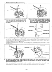
... the shuttle body. At this point the needle thread take -up is caught by the movable knife as shown in the figure above from its stroke. Needle and bobbin threads trimming 0 (1) When the needle rises 2 mm (2.2 mm with fixed knife removed (4) The needle and bobbin threads caught by the rotary hook point under the needle plate, and the loop spreading occurs. Q-9 Bobbin thread O Fixed knife Needle thread Movable knife Lower thread finger...
... the shuttle body. At this point the needle thread take -up is caught by the movable knife as shown in the figure above from its stroke. Needle and bobbin threads trimming 0 (1) When the needle rises 2 mm (2.2 mm with fixed knife removed (4) The needle and bobbin threads caught by the rotary hook point under the needle plate, and the loop spreading occurs. Q-9 Bobbin thread O Fixed knife Needle thread Movable knife Lower thread finger...

Service Manual
Page 21
... screw 0 of the needle bar clamp 0 and remove the needle bar upward. (3) Remove the two screws O and the needle bar bracket guide 0. (4) Loosen the screws ® and 0. Needle bar mechanism Om, P a / r• 0 (1) Remove the oil caps and . (2) Set the needle bar 0 at the lowest position by turning the machine pulley. Machine covers • s -6( • • (1) Loosen the screw 0 and remove the needle @. (2) Remove the three screws 0, then remove the face plate 0 and the face plate packing 0. (3) Remove the eight screws ®, then remove the rear cover...
... screw 0 of the needle bar clamp 0 and remove the needle bar upward. (3) Remove the two screws O and the needle bar bracket guide 0. (4) Loosen the screws ® and 0. Needle bar mechanism Om, P a / r• 0 (1) Remove the oil caps and . (2) Set the needle bar 0 at the lowest position by turning the machine pulley. Machine covers • s -6( • • (1) Loosen the screw 0 and remove the needle @. (2) Remove the three screws 0, then remove the face plate 0 and the face plate packing 0. (3) Remove the eight screws ®, then remove the rear cover...

Service Manual
Page 29
... needle 0 and the rotary hook point to 0.05-0.1 mm. (5) Install the needle plate. (6) Install the slide plate O. (7) Adjust the feed timing. (8) Set the feed amount to pass easily. 0 Make sure the rotary hook ©does not strike the lower thread finger. - 28 - To adjust the timing, turn the level feed eccentric wheel m and the feed lifting eccentric wheel ®by turning the machine pulley (2.2 mm when sewing thick materials). X In model DB2-B7910, install the needle plate...
... needle 0 and the rotary hook point to 0.05-0.1 mm. (5) Install the needle plate. (6) Install the slide plate O. (7) Adjust the feed timing. (8) Set the feed amount to pass easily. 0 Make sure the rotary hook ©does not strike the lower thread finger. - 28 - To adjust the timing, turn the level feed eccentric wheel m and the feed lifting eccentric wheel ®by turning the machine pulley (2.2 mm when sewing thick materials). X In model DB2-B7910, install the needle plate...

Service Manual
Page 35
... and reverse feed stitch length are adjusted together. (1) Set the feed regulating dial 0 to mark 3. (2) Sew 11 stitches forward and reverse at the inching speed (215 spm). (3) Adjust as follows when the forward and reverse feed stitch lengths are different. 1) Remove the rear cover. 2) Loosen the screw 0. 3) When the stitch length for forward feed is less than for reverse feed, set the hole of the pin upper. When the stitch length for forward feed is greater than for reverse feed, set the hole of the pin 0 lower. 5. X Feed adjustment should reverse...
... and reverse feed stitch length are adjusted together. (1) Set the feed regulating dial 0 to mark 3. (2) Sew 11 stitches forward and reverse at the inching speed (215 spm). (3) Adjust as follows when the forward and reverse feed stitch lengths are different. 1) Remove the rear cover. 2) Loosen the screw 0. 3) When the stitch length for forward feed is less than for reverse feed, set the hole of the pin upper. When the stitch length for forward feed is greater than for reverse feed, set the hole of the pin 0 lower. 5. X Feed adjustment should reverse...

Service Manual
Page 39
... number is decreased when the potentiometer is rotated clockwise. (2) Sew several stitches. (3) Repeat (1) and (2) to match the indicated pitch with the indicated one if the feed dog height is matched, firmly tighten the screws €4. )K Apply a small amount of grease on the branch of the reverse link lever assembly 0 and on the display. 2 Make sure the actual pitch is different, adjust...
... number is decreased when the potentiometer is rotated clockwise. (2) Sew several stitches. (3) Repeat (1) and (2) to match the indicated pitch with the indicated one if the feed dog height is matched, firmly tighten the screws €4. )K Apply a small amount of grease on the branch of the reverse link lever assembly 0 and on the display. 2 Make sure the actual pitch is different, adjust...

Service Manual
Page 41
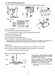
... the right and left adjustment of the sensor position can be done by loosening the screw 0. (2) Raise the presser foot 0 using the presser bar lifter 0. (3) After loosening the screw 0, remove the sensor guard O and the presser foot 0. (4) Slide the slide plate 0 in the range of the arrow. (5) Remove the screw 0 and the needle plate O. X Do not damage the cover O when removing the needle plate O. X Drill a sensor hole with the hole of sensor guards...
... the right and left adjustment of the sensor position can be done by loosening the screw 0. (2) Raise the presser foot 0 using the presser bar lifter 0. (3) After loosening the screw 0, remove the sensor guard O and the presser foot 0. (4) Slide the slide plate 0 in the range of the arrow. (5) Remove the screw 0 and the needle plate O. X Do not damage the cover O when removing the needle plate O. X Drill a sensor hole with the hole of sensor guards...
Service Manual
Page 42
... materials. (3) Disconnect the synchronizer cord @. (4) Set the correction switch 0 to ON. (5) Set the sensitivity control switch() to 0.5-1 mm, using the screw 0. The number should blink. When the feed dog is changed. 0 0 0 0 0 qt„r, NEDgyLPmOESIT S%E "g" Distance indication 0 2 PLY SENSOR A B C D CORRECTION Lni] 0 0 481 Oy 14 TACK STITCHES 0 0 (1) Turn off the power. (2) Seta material under the needle plate, adjust the gap between the upper surface needle plate 0 and the bottom of...
... materials. (3) Disconnect the synchronizer cord @. (4) Set the correction switch 0 to ON. (5) Set the sensitivity control switch() to 0.5-1 mm, using the screw 0. The number should blink. When the feed dog is changed. 0 0 0 0 0 qt„r, NEDgyLPmOESIT S%E "g" Distance indication 0 2 PLY SENSOR A B C D CORRECTION Lni] 0 0 481 Oy 14 TACK STITCHES 0 0 (1) Turn off the power. (2) Seta material under the needle plate, adjust the gap between the upper surface needle plate 0 and the bottom of...

Service Manual
Page 50
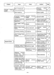
... z Replace needle. Needle breakage Improper timing feed --I Needle bar rise Improper needle to rotary hook timing Needle bar height HNeedle to rotary hook gap Thread wiper too high Thread position wiper Adjust feed timing. 32 Adjust needle to 31 rotary hook timing. Bent needle. Reinstall needle. TROUBLESHOOTING GUIDE 1. Machine head Problem Cause Improper needle installation Bent needle. Adjust needle to 31 rotary hook timing. Adjust thread wiper. 45 Thread breakage Improper threading threading Rethread. Blunt needle tip, jammed eye. Adjust bobbin 5 thread tension...
... z Replace needle. Needle breakage Improper timing feed --I Needle bar rise Improper needle to rotary hook timing Needle bar height HNeedle to rotary hook gap Thread wiper too high Thread position wiper Adjust feed timing. 32 Adjust needle to 31 rotary hook timing. Bent needle. Reinstall needle. TROUBLESHOOTING GUIDE 1. Machine head Problem Cause Improper needle installation Bent needle. Adjust needle to 31 rotary hook timing. Adjust thread wiper. 45 Thread breakage Improper threading threading Rethread. Blunt needle tip, jammed eye. Adjust bobbin 5 thread tension...
Service Manual
Page 51
... Page Thread breaks frays Burr in material. Needle tip Blunt rotary hook point Rotary hook point Reinstall needle. 4 Replace needle with sandpaper. Improper threading Threading Rethread. 4 Poor presser foot contact Presser bar pressure Presser bar height Skipped stitches --I Blunt needle tip Remove with larger count needle. i Bobbin spins during thread cutting and bobbin thread remainder gets too short; Thread take-u spring tension Adjust take -up spring tension too weak, won 't rise. Adjust needle to rotary hook timing _1Needle thread remainder...
... Page Thread breaks frays Burr in material. Needle tip Blunt rotary hook point Rotary hook point Reinstall needle. 4 Replace needle with sandpaper. Improper threading Threading Rethread. 4 Poor presser foot contact Presser bar pressure Presser bar height Skipped stitches --I Blunt needle tip Remove with larger count needle. i Bobbin spins during thread cutting and bobbin thread remainder gets too short; Thread take-u spring tension Adjust take -up spring tension too weak, won 't rise. Adjust needle to rotary hook timing _1Needle thread remainder...
Service Manual
Page 52
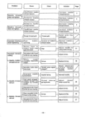
... - Adjust needle to rotary hook stop gap too small H Improper thread cutting Movable knife, fixed knife do not overlap 1 c. replace thread cutter solenoid. not cut Worn, rough movable, fixed knife edges Movable knife does not move Gap Knives Thread cutter signal relayed? Improper needle installation Needle facing - Bobbin thread Poor movable knife, fixed knife cutting. Improper looping stitch tightening Poor bobbin spinning Tension of bobbin thread leader Replace bobbin, z ,Z rotary hook. Problem Cause Check Solution Page Needle thread...
... - Adjust needle to rotary hook stop gap too small H Improper thread cutting Movable knife, fixed knife do not overlap 1 c. replace thread cutter solenoid. not cut Worn, rough movable, fixed knife edges Movable knife does not move Gap Knives Thread cutter signal relayed? Improper needle installation Needle facing - Bobbin thread Poor movable knife, fixed knife cutting. Improper looping stitch tightening Poor bobbin spinning Tension of bobbin thread leader Replace bobbin, z ,Z rotary hook. Problem Cause Check Solution Page Needle thread...

Service Manual
Page 53
.../ Replace with tester Adjust tension release. Excessive material, presser foot resistance Timing too early; - wipes thread before tension disc closes. dThread cutter signal not relayed dNeedle thread remainder too long Thread wiper does not function. Adjust pretension. 5 Needle size Delay up Thread 1 cutter Thread cutter solenoid does not function. Thread wiper operation too short Tension opening disc Thread take -up needle 35 stop position Check with presser foot have back channel. 7 Adjust operating time. z Adjust operating time. - 56 - Problem Cause...
.../ Replace with tester Adjust tension release. Excessive material, presser foot resistance Timing too early; - wipes thread before tension disc closes. dThread cutter signal not relayed dNeedle thread remainder too long Thread wiper does not function. Adjust pretension. 5 Needle size Delay up Thread 1 cutter Thread cutter solenoid does not function. Thread wiper operation too short Tension opening disc Thread take -up needle 35 stop position Check with presser foot have back channel. 7 Adjust operating time. z Adjust operating time. - 56 - Problem Cause...


