
Parts Manual - Multi
Page 6
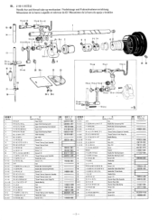
...-up Lever Link 5- WrAfif.: Needle bar and thread take-up Lever Hinge Pin Needle Bearing 7 m/PF Felt 97 L₹4X4 Wick 4X4 97 E₹4 X4 Wick 4X4 F .$*7/6.35947 7: Screw if ii 4, Washer /SU /WS,/ 5)3-U Needle Bar Bushing (Upper) /, 9 tfr,/ , 9/PD Needle Bar Bushing (Lower) F 1 *7/5.95 /s 9 *ky Screw 5.95 Needle Bar E. 7., 7, /, 9 Needle 7979₹FY.*'.93.18 ,, 9 4Irr, 7 3, / -4 i3, 7 -7 Screw 3.18 Needle Bar Guide Slide Block ,• 9 ,Nr,-1 F 7.f4 /.u..g, Needle Bar Thread Guide Needle Plate #54h7/4.31 Screw 4.37 A.: 94999 Shuttle...
...-up Lever Link 5- WrAfif.: Needle bar and thread take-up Lever Hinge Pin Needle Bearing 7 m/PF Felt 97 L₹4X4 Wick 4X4 97 E₹4 X4 Wick 4X4 F .$*7/6.35947 7: Screw if ii 4, Washer /SU /WS,/ 5)3-U Needle Bar Bushing (Upper) /, 9 tfr,/ , 9/PD Needle Bar Bushing (Lower) F 1 *7/5.95 /s 9 *ky Screw 5.95 Needle Bar E. 7., 7, /, 9 Needle 7979₹FY.*'.93.18 ,, 9 4Irr, 7 3, / -4 i3, 7 -7 Screw 3.18 Needle Bar Guide Slide Block ,• 9 ,Nr,-1 F 7.f4 /.u..g, Needle Bar Thread Guide Needle Plate #54h7/4.31 Screw 4.37 A.: 94999 Shuttle...
Parts Manual - Multi
Page 17
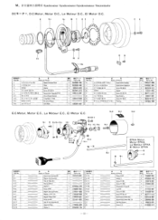
... Parts Screw 3 X6D Washer 4 Screw 4X10D Screw 4X I2DA Synchronizer Cover #3 Level #2 Screw 4 X 10DC Screw 476-32X14 Synchronizer Holder Bar Synchronizer Holder Bar 115 Slip Ring Support Screw 4.37 Me irl,3A - a Name of Parts Syncronizer Assjmely #18 Magnet Stud Assembly Hole IC Holder #13 Bearing 6201VV Washer 3 Screw 3 X6D Magnet Setting Bracket Magnet 12X10.7X6 Magnet Holder Plate Screw 6 X25D Hole IC Cord Assembly #4 Adjusting Plate Washer 3 1@1≥3 06a7- f',1-t -m Gord Holder L f^7357 -40X6 Screw 357-40X6 y- >is i;',..s. V Q'ty Parts...
... Parts Screw 3 X6D Washer 4 Screw 4X10D Screw 4X I2DA Synchronizer Cover #3 Level #2 Screw 4 X 10DC Screw 476-32X14 Synchronizer Holder Bar Synchronizer Holder Bar 115 Slip Ring Support Screw 4.37 Me irl,3A - a Name of Parts Syncronizer Assjmely #18 Magnet Stud Assembly Hole IC Holder #13 Bearing 6201VV Washer 3 Screw 3 X6D Magnet Setting Bracket Magnet 12X10.7X6 Magnet Holder Plate Screw 6 X25D Hole IC Cord Assembly #4 Adjusting Plate Washer 3 1@1≥3 06a7- f',1-t -m Gord Holder L f^7357 -40X6 Screw 357-40X6 y- >is i;',..s. V Q'ty Parts...
Parts Manual - Multi
Page 26
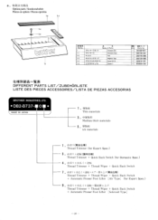
... BROTHER INDUSTRIES, LTD. • DB2-B737- 0 N • MADE IN JAPAN 1 . Medium thick materials 5 P-4i--t-til1 ick materials • (tiMf±a) Thread Trimmer (for Export Spec.) 3 . -`f:E/II)+4.C(1=1A{±4) Thread Trimmer + Quick Back Switch (for Domestic Spec.) 41:-VJ ') + .;(f:4"1, -f + Thread Trimmer + Thread Wiper + Quick Back Switch • 41:-W +4"t+ -LT -1T -1 -± r (VI •f±41) Thread Trimmer + Thread Wiper + Quick Back Switch + Automatic Presser Foot Lifter [Air Type] (for Export Spec.) 9. Thread...
... BROTHER INDUSTRIES, LTD. • DB2-B737- 0 N • MADE IN JAPAN 1 . Medium thick materials 5 P-4i--t-til1 ick materials • (tiMf±a) Thread Trimmer (for Export Spec.) 3 . -`f:E/II)+4.C(1=1A{±4) Thread Trimmer + Quick Back Switch (for Domestic Spec.) 41:-VJ ') + .;(f:4"1, -f + Thread Trimmer + Thread Wiper + Quick Back Switch • 41:-W +4"t+ -LT -1T -1 -± r (VI •f±41) Thread Trimmer + Thread Wiper + Quick Back Switch + Automatic Presser Foot Lifter [Air Type] (for Export Spec.) 9. Thread...
Parts Manual - Multi
Page 27
B-8 B-8-1 B-10 B-11-1 B-11-2 B-15 „;„A Name of Parts 5- .,' E,5.',,,:.-.. - ./' L: -3.:, 4 7/ - 1•) OR** Ref.No.
B-8 B-8-1 B-10 B-11-1 B-11-2 B-15 „;„A Name of Parts 5- .,' E,5.',,,:.-.. - ./' L: -3.:, 4 7/ - 1•) OR** Ref.No.
Network Users Manual - English
Page 2
... EACH COMPONENT 2 (NAME OF EACH PART) 3 .CONFIGURATION; 4 (PRINCIPLE OF CONTROL SYSTEM) 5 1-ADJUSTMENT 7 DC Servomotor 7 I i Needle position detector (synchronizer) 7 r31 C•ontrol box 9 T• readle 10 O Brush replacement 10 lel Motor brake spacing 11 pi Checking the lamp terminal code 11 Standing work machine 12 pi Application to production control system 13 ((OPERATION INSTRUCTION 14 Installation of operation box 14 M Motor and control box (Models DB2-B737 • B747 • B748...
... EACH COMPONENT 2 (NAME OF EACH PART) 3 .CONFIGURATION; 4 (PRINCIPLE OF CONTROL SYSTEM) 5 1-ADJUSTMENT 7 DC Servomotor 7 I i Needle position detector (synchronizer) 7 r31 C•ontrol box 9 T• readle 10 O Brush replacement 10 lel Motor brake spacing 11 pi Checking the lamp terminal code 11 Standing work machine 12 pi Application to production control system 13 ((OPERATION INSTRUCTION 14 Installation of operation box 14 M Motor and control box (Models DB2-B737 • B747 • B748...
Network Users Manual - English
Page 4
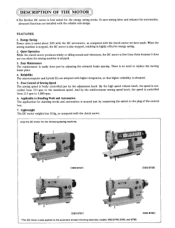
... sewing speed knob, the speed is controlled from 215 spm to 3,000 spm. 6. When the sewing machine is stopped, the DC motor is no need to replace the moving brake plate. 4. And by adjusting the solenoid brake spacing. ©DESCRIPTION OF THE MOTOR *The Brother DC motor is best suited for the following sewing machines. [DB2-B7371 4 ,7 [DB2-6738] 4 [DB2-67911 *The DC motor is also applied to the automatic thread trimming machines, models DB2...
... sewing speed knob, the speed is controlled from 215 spm to 3,000 spm. 6. When the sewing machine is stopped, the DC motor is no need to replace the moving brake plate. 4. And by adjusting the solenoid brake spacing. ©DESCRIPTION OF THE MOTOR *The Brother DC motor is best suited for the following sewing machines. [DB2-B7371 4 ,7 [DB2-6738] 4 [DB2-67911 *The DC motor is also applied to the automatic thread trimming machines, models DB2...

Network Users Manual - English
Page 6
... Operation box Speed detection CPU Solenoid brake transistor CONTROL CIRCUIT UNIT NOTE: The sections enclosed by the broken line indicate where high voltage is applied. In setting down the machine head or touching the needle, be sure to turn off the power switch, remove the front cover and confirm the pilot lamp "OFF". * It is dangerous to ground. (A ground code...
... Operation box Speed detection CPU Solenoid brake transistor CONTROL CIRCUIT UNIT NOTE: The sections enclosed by the broken line indicate where high voltage is applied. In setting down the machine head or touching the needle, be sure to turn off the power switch, remove the front cover and confirm the pilot lamp "OFF". * It is dangerous to ground. (A ground code...
Network Users Manual - English
Page 9
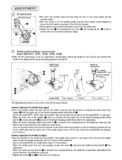
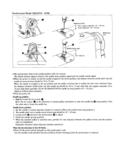
... to loosen the belt tension sometimes. ADJUSTMENT D 1 DC Servomotor Rotating direction 10 mm 0 0 o • • C) 0 ooS *Set down . Synchronizer detects the needle by two hole IC and controls the needle down hole IC 0 is 22-26 mm.) Position Adjustment for Needle Up Signal *Stop the machine at the needle down stop hole IC 0 for adjustment. And when in the reverse direction, the needle bar comes down the machine head and then hang...
... to loosen the belt tension sometimes. ADJUSTMENT D 1 DC Servomotor Rotating direction 10 mm 0 0 o • • C) 0 ooS *Set down . Synchronizer detects the needle by two hole IC and controls the needle down hole IC 0 is 22-26 mm.) Position Adjustment for Needle Up Signal *Stop the machine at the needle down stop hole IC 0 for adjustment. And when in the reverse direction, the needle bar comes down the machine head and then hang...
Network Users Manual - English
Page 10
... the power switch and pull out the synchronizer code. The thread trimmer signal is timed to adjust. * Check the needle up position 1. Use the machine with standard function (without thread trimming) until the synchronizer is within the belt cover reference lines, the distance between needle plate top and needle set screws 0 in the up position and the pulley reference line is replaced. Needle down position, the distance between needle plate top and needle...
... the power switch and pull out the synchronizer code. The thread trimmer signal is timed to adjust. * Check the needle up position 1. Use the machine with standard function (without thread trimming) until the synchronizer is within the belt cover reference lines, the distance between needle plate top and needle set screws 0 in the up position and the pulley reference line is replaced. Needle down position, the distance between needle plate top and needle...
Network Users Manual - English
Page 11
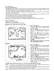
... 3: When any volume knob is changed by mistake, turn off the front cover. 2. 131 Control box Control Box (Model DB2-B737) The high speed volume, backtack stitch volume, power lamp, needle position switch, one 15A fuse for the 110-240V single-phase type, two 5A fuses for the 200240V three-phase type and two 3A fuses for adjustment. The power circuit board is at 1800 spm...
... 3: When any volume knob is changed by mistake, turn off the front cover. 2. 131 Control box Control Box (Model DB2-B737) The high speed volume, backtack stitch volume, power lamp, needle position switch, one 15A fuse for the 110-240V single-phase type, two 5A fuses for the 200240V three-phase type and two 3A fuses for adjustment. The power circuit board is at 1800 spm...
Network Users Manual - English
Page 12
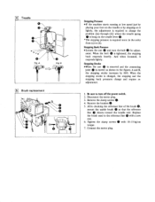
... turn off the power switch. 2. And when loosened, it lightly, the adjustment is required to turn the bolt 0 for adjust- Be sure to change the position [(a) through (d)] where the treadle spring is hung on the treadle lever 0 * The stepping pressure is changed, the stepping and the stepping back pressures change and require readjustment. 1. Replace the brush used to (d). Connect the motor plug. . Remove the clamp screws 0. 4. ment. When...
... turn off the power switch. 2. And when loosened, it lightly, the adjustment is required to turn the bolt 0 for adjust- Be sure to change the position [(a) through (d)] where the treadle spring is hung on the treadle lever 0 * The stepping pressure is changed, the stepping and the stepping back pressures change and require readjustment. 1. Replace the brush used to (d). Connect the motor plug. . Remove the clamp screws 0. 4. ment. When...

Network Users Manual - English
Page 14
.../disconnecting the plug. 1. Secure the screw 0 with the nut 0 , or it happens to affect the function of 100 mA or more to be loose. Go. Treadle Lever Position *While keeping the treadle lever 0 lowered, turn off the power switch before connecting/disconnecting the plug. *Remove the motor cover. 8 Standing work machine *The code connection and the treadle lever are fixed for the timer, relay, sensor...
.../disconnecting the plug. 1. Secure the screw 0 with the nut 0 , or it happens to affect the function of 100 mA or more to be loose. Go. Treadle Lever Position *While keeping the treadle lever 0 lowered, turn off the power switch before connecting/disconnecting the plug. *Remove the motor cover. 8 Standing work machine *The code connection and the treadle lever are fixed for the timer, relay, sensor...
Network Users Manual - English
Page 16
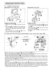
... is turned on the Table 1. Four screws 0 are provided. The start backtack speed increases. And use (Models DB2-B737 • B747 • B748 • B791 • B795 • B798) Power switch O0 a 11 brother 0©000 *Push the "ON" button of operation box Models DB2-B737 • B747 • B748 • B791 • • :g• Models DB2-B793 • B795- Fix the mounting plate 0 on , the machine starts running in proportion...
... is turned on the Table 1. Four screws 0 are provided. The start backtack speed increases. And use (Models DB2-B737 • B747 • B748 • B791 • B795 • B798) Power switch O0 a 11 brother 0©000 *Push the "ON" button of operation box Models DB2-B737 • B747 • B748 • B791 • • :g• Models DB2-B793 • B795- Fix the mounting plate 0 on , the machine starts running in proportion...
Network Users Manual - English
Page 17
... working with the counter switches A, B, C and D. And when the lower switch is pressed, the number increases. *The machine runs according to "0" for the fixed stitch sewing N. 2. O For Fixed Stitch Sewing and Thread Trimming With the switch 0 pressed, the fixed stitch sewing is pressed, the number of stitches decreases. 3 Operation box (Models DB2-B737 • B747 • B791 • B793 • B795 • B798) *The switch settings and the number of stitches cannot be set using...
... working with the counter switches A, B, C and D. And when the lower switch is pressed, the number increases. *The machine runs according to "0" for the fixed stitch sewing N. 2. O For Fixed Stitch Sewing and Thread Trimming With the switch 0 pressed, the fixed stitch sewing is pressed, the number of stitches decreases. 3 Operation box (Models DB2-B737 • B747 • B791 • B793 • B795 • B798) *The switch settings and the number of stitches cannot be set using...

Network Users Manual - English
Page 18
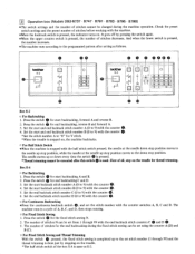
... is operating, the machine enters the reverse sewing mode. Thread trimming is performed after end backtack when the treadle is set to the reverse position. If the actuator is pressed while the machine is pressed. • . . O Guide to reverse) Start backtack End backtack Start/end backtack Fixed stitch sewing with thread trimming ON (thread trimming performed with treadle depressed forward) Fixed stitch sewing Start backtack End backtack Start/end backtack Continuous backtack (Automatic thread trimming...
... is operating, the machine enters the reverse sewing mode. Thread trimming is performed after end backtack when the treadle is set to the reverse position. If the actuator is pressed while the machine is pressed. • . . O Guide to reverse) Start backtack End backtack Start/end backtack Fixed stitch sewing with thread trimming ON (thread trimming performed with treadle depressed forward) Fixed stitch sewing Start backtack End backtack Start/end backtack Continuous backtack (Automatic thread trimming...
Network Users Manual - English
Page 19
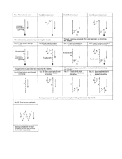
No.1 Normal lock stitch Actuator correction No.2 Start backtack B/ A1 / V 4 Thread trimming activated by reversing the treadle. No.5 Fixed stitch sewing only No.6 Start backtack and fixed stitch sewing Fixed stitch I N Actuator I correction I B/ Ai / N Fixed stitch I No.3 End backtack No.4 Start/end backtack A I B/ / A C/ I /B/ Ii"A Thread trimming activated by reversing the treadle. No.7 Fixed stitch sewing and end backtack No.8 Start/end backtack and fixed stitch sewing Fixed stitch NI 1 A i B/ NI Fixed stitch I / ID A C/ / ID Thread trimming activated after end ...
No.1 Normal lock stitch Actuator correction No.2 Start backtack B/ A1 / V 4 Thread trimming activated by reversing the treadle. No.5 Fixed stitch sewing only No.6 Start backtack and fixed stitch sewing Fixed stitch I N Actuator I correction I B/ Ai / N Fixed stitch I No.3 End backtack No.4 Start/end backtack A I B/ / A C/ I /B/ Ii"A Thread trimming activated by reversing the treadle. No.7 Fixed stitch sewing and end backtack No.8 Start/end backtack and fixed stitch sewing Fixed stitch NI 1 A i B/ NI Fixed stitch I / ID A C/ / ID Thread trimming activated after end ...
Network Users Manual - English
Page 23
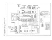
...O 11) rO N Potentiometer 3 2 Hem detection Machine head Thread wiper solenoid 5.00 Reverse Reverse solenoid 7.40 Cycle utput 2 2 4 8 4 0 Thread trimming solenoid 6.7O 2 3 Solenoid presser foot ch lifter 15W.1O4 4 2 O 0 Presser foot litre 2 switch Brake Brake coil 8.00 -r Treadle unit Power switch r 0ro 0 000 .0.0^0/\ O O...used for 380-415V versions. Red Synchronizer #13-2 (internal) DN UP ENC 4 2 Gray Black White Yellow Brown 1 GND 2 +5V 3 DN 4 OV 5 NO.SYC 6 GND 7 UP 8 ENC 2 O-rj 1 4 .1.7:-,0 3 111°426 1O3--COI OO--O O 1119153 1290 0C--0a 197 Operation...
...O 11) rO N Potentiometer 3 2 Hem detection Machine head Thread wiper solenoid 5.00 Reverse Reverse solenoid 7.40 Cycle utput 2 2 4 8 4 0 Thread trimming solenoid 6.7O 2 3 Solenoid presser foot ch lifter 15W.1O4 4 2 O 0 Presser foot litre 2 switch Brake Brake coil 8.00 -r Treadle unit Power switch r 0ro 0 000 .0.0^0/\ O O...used for 380-415V versions. Red Synchronizer #13-2 (internal) DN UP ENC 4 2 Gray Black White Yellow Brown 1 GND 2 +5V 3 DN 4 OV 5 NO.SYC 6 GND 7 UP 8 ENC 2 O-rj 1 4 .1.7:-,0 3 111°426 1O3--COI OO--O O 1119153 1290 0C--0a 197 Operation...
Network Users Manual - English
Page 24
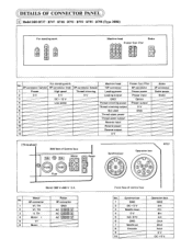
... 1 GND 2 DC + 5 V 3 Needle down 4 0 V 5 NO. SYC 6 GND 7 Needle up 8 Encoder 9 10 Operation box GND Din Cin Bin Ain Cout Bout Aout 0 V DC + 5 V TH 4 Motor + 5 Vf 6 Motor - TH 3 if. TH 2 Vf. .DETAILS OF CONNECTOR PANEL 1 Model DB2-B737 • B747 • B748 • B791 • B793 • B795 • B798 (Type 3O0B) For standing work O th` 0 CD CD Machine head Presser foot lifter 000...
... 1 GND 2 DC + 5 V 3 Needle down 4 0 V 5 NO. SYC 6 GND 7 Needle up 8 Encoder 9 10 Operation box GND Din Cin Bin Ain Cout Bout Aout 0 V DC + 5 V TH 4 Motor + 5 Vf 6 Motor - TH 3 if. TH 2 Vf. .DETAILS OF CONNECTOR PANEL 1 Model DB2-B737 • B747 • B748 • B791 • B793 • B795 • B798 (Type 3O0B) For standing work O th` 0 CD CD Machine head Presser foot lifter 000...

Network Users Manual - English
Page 25
... V Low speed [Single-phase] Side face of control box 15A Motor Power O O Fuse Machine head No. 12P connector 1 Leading power 2 Leading output 3 GND 4 Thread trimming power 5 Thread trimming output 6 Not used 7 Thread wiper power 8 Thread wiper output - 9 Reverse input 10 Reverse power 11 Reverse output 12 0V Presser foot lifter 6P connector Cloth presser power Presser input Option Cloth presser output 0 GND Brake No. 2P connector 1 Brake power 2 Brake Front face of control box Operation panel...
... V Low speed [Single-phase] Side face of control box 15A Motor Power O O Fuse Machine head No. 12P connector 1 Leading power 2 Leading output 3 GND 4 Thread trimming power 5 Thread trimming output 6 Not used 7 Thread wiper power 8 Thread wiper output - 9 Reverse input 10 Reverse power 11 Reverse output 12 0V Presser foot lifter 6P connector Cloth presser power Presser input Option Cloth presser output 0 GND Brake No. 2P connector 1 Brake power 2 Brake Front face of control box Operation panel...
Network Users Manual - English
Page 26
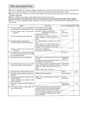
... not work. (thread trimming, reverse rotation, thread wiper, and presser) 9. Abnormality related to plug into another outlet.) Fuse blown: 3-phase 5 A fuse (2 pcs.) Single-phase 15 A fuse (1 pc.) (Replace with the treadle set at high speed. Check the power source voltage. (Try to automatic backtacking, etc. 10. The machine pulley is so heavy to the maximum.► Control box Power switch assembly Control box 5. The machine starts running...
... not work. (thread trimming, reverse rotation, thread wiper, and presser) 9. Abnormality related to plug into another outlet.) Fuse blown: 3-phase 5 A fuse (2 pcs.) Single-phase 15 A fuse (1 pc.) (Replace with the treadle set at high speed. Check the power source voltage. (Try to automatic backtacking, etc. 10. The machine pulley is so heavy to the maximum.► Control box Power switch assembly Control box 5. The machine starts running...


