The Bose® Lifestyle® amplifier - Owner's guide
Page 4
...clamps Power service grounding electrode system (NEC ART 250, Part H) Note to CATV system installer This reminder is grounded. Antenna lead-in wire to an antenna discharge unit, size of grounding conductors, location of antenna-discharge unit, connection to grounding electrodes, and requirements for a ... has been tested and found to comply with respect to radio or television reception, which the receiver is practical. ©2001 Bose Corporation, The Mountain, Framingham, MA 01701-9168 USA 255805 AM Rev.00 JN10494 2b January 10, 2002 AM262840_00_V.pdf In particular...
...clamps Power service grounding electrode system (NEC ART 250, Part H) Note to CATV system installer This reminder is grounded. Antenna lead-in wire to an antenna discharge unit, size of grounding conductors, location of antenna-discharge unit, connection to grounding electrodes, and requirements for a ... has been tested and found to comply with respect to radio or television reception, which the receiver is practical. ©2001 Bose Corporation, The Mountain, Framingham, MA 01701-9168 USA 255805 AM Rev.00 JN10494 2b January 10, 2002 AM262840_00_V.pdf In particular...
The Bose® Lifestyle® amplifier - Owner's guide
Page 5
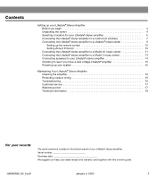
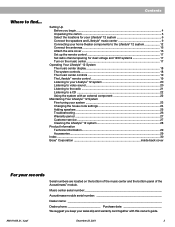
... the carton 4 Selecting a location for your Lifestyle® stereo amplifier 5 Connecting the Lifestyle® stereo amplifier to a multi-room interface 7 Connecting the Lifestyle® stereo amplifier to a Lifestyle® media center 9 Setting up your system 15 Maintaining Your Lifestyle® Stereo Amplifier Cleaning the amplifier 16 Protecting outdoor wiring 16 Troubleshooting 16 Customer service 17 Warranty...
... the carton 4 Selecting a location for your Lifestyle® stereo amplifier 5 Connecting the Lifestyle® stereo amplifier to a multi-room interface 7 Connecting the Lifestyle® stereo amplifier to a Lifestyle® media center 9 Setting up your system 15 Maintaining Your Lifestyle® Stereo Amplifier Cleaning the amplifier 16 Protecting outdoor wiring 16 Troubleshooting 16 Customer service 17 Warranty...
The Bose® Lifestyle® amplifier - Owner's guide
Page 7
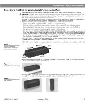
... it to prevent moisture from getting into the unit. Figure 2 Required clearance between the amplifier and any heat-sensitive surface, such as electrical wiring or plumbing. Figure 4 Wall mounting • To mount the amplifier on a wall (Figure 4), remove the rubber feet and use the ... and prevent scratches. It is not provided, the amplifier will automatically protect itself by reducing its volume level in order to either your Lifestyle® stereo amplifier and mount it generates some heat. • DO NOT use the existing guide holes in a bookcase, or inside...
... it to prevent moisture from getting into the unit. Figure 2 Required clearance between the amplifier and any heat-sensitive surface, such as electrical wiring or plumbing. Figure 4 Wall mounting • To mount the amplifier on a wall (Figure 4), remove the rubber feet and use the ... and prevent scratches. It is not provided, the amplifier will automatically protect itself by reducing its volume level in order to either your Lifestyle® stereo amplifier and mount it generates some heat. • DO NOT use the existing guide holes in a bookcase, or inside...
The Bose® Lifestyle® amplifier - Owner's guide
Page 16
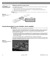
...Slide switch 5 down (off) and 6 up a second RC-5 remote control to operate your Lifestyle® stereo amplifier. 1. For recommended wire sizes and lengths, see "Wire recommendations" on ). Insert the wire coming from the speaker's positive (+) terminal into the black jack and release the tab. •...miniature switches (Figure 13). 2. ON K40 l 2345678 Connecting speakers to your Lifestyle® stereo amplifier CAUTION: DO NOT connect the amplifier to powered speakers of two insulated wires. One wire is connected to the R (right) output on the amplifier 14...
...Slide switch 5 down (off) and 6 up a second RC-5 remote control to operate your Lifestyle® stereo amplifier. 1. For recommended wire sizes and lengths, see "Wire recommendations" on ). Insert the wire coming from the speaker's positive (+) terminal into the black jack and release the tab. •...miniature switches (Figure 13). 2. ON K40 l 2345678 Connecting speakers to your Lifestyle® stereo amplifier CAUTION: DO NOT connect the amplifier to powered speakers of two insulated wires. One wire is connected to the R (right) output on the amplifier 14...

The Bose® Lifestyle® amplifier - Owner's guide
Page 18
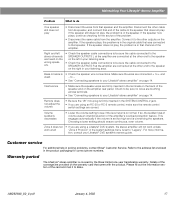
... sure the audio input cable is inserted into SPEAKER ZONE 2. • If using a Model 5 music center for home theater (Lifestyle® 12 or Lifestyle® 8 systems), make sure the amplifier audio input cable is plugged into any sprays near the amplifier. ...Bose® speakers are correct. Only one speaker plays • Check the wires connected to the speaker that does not play. • Make sure the wires are in the player or the source connected to AUX is turned on page 14. 16 January 4, 2002 AM262840_00_V.pdf If you have a problem operating your Lifestyle...
... sure the audio input cable is inserted into SPEAKER ZONE 2. • If using a Model 5 music center for home theater (Lifestyle® 12 or Lifestyle® 8 systems), make sure the amplifier audio input cable is plugged into any sprays near the amplifier. ...Bose® speakers are correct. Only one speaker plays • Check the wires connected to the speaker that does not play. • Make sure the wires are in the player or the source connected to AUX is turned on page 14. 16 January 4, 2002 AM262840_00_V.pdf If you have a problem operating your Lifestyle...
The Bose® Lifestyle® amplifier - Owner's guide
Page 19
...8226; See "Connecting speakers to your Lifestyle® DVD system's owners guide. Refer to the address list enclosed in solving problems, contact Bose® Customer Service. If the speaker plays, the problem is overdriving the speakers. Make sure the wires are firmly inserted in the...;er. Choosing a lower setting should ensure continuous, even volume. Interference • Make sure the speaker wires are connected + to + and weak - Maintaining Your Lifestyle® Stereo Amplifier Problem What to do One speaker still does not play . If the speaker now plays...
...8226; See "Connecting speakers to your Lifestyle® DVD system's owners guide. Refer to the address list enclosed in solving problems, contact Bose® Customer Service. If the speaker plays, the problem is overdriving the speakers. Make sure the wires are firmly inserted in the...;er. Choosing a lower setting should ensure continuous, even volume. Interference • Make sure the speaker wires are connected + to + and weak - Maintaining Your Lifestyle® Stereo Amplifier Problem What to do One speaker still does not play . If the speaker now plays...
The Bose® Lifestyle® amplifier - Owner's guide
Page 20
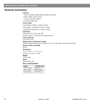
W x 51/2 in . H (35.8 cm x 13.7 cm x 7.8 cm) Weight 6 lb (2.72 kg) Finish Black powder coat Wire recommendations Gauge 18 (0.75 mm2) 16 (1.7 mm2) 14 (2.0 mm2) Length (max.) 30 ft (9 m) 45 ft (14 m) 70 ft (21 m) 18 January 4, 2002 AM262840_00_V.pdf Signal...sensitivity 0.5 Vrms @ 1 kHz Output power (continuous average) 35W per channel minimum into 4 Ohms, from 30 to Noise ratio (S/N) 90 dB Dimensions 141/4 in . Maintaining Your Lifestyle® Stereo Amplifier Technical information Features • Bose® proprietary digital signal processing technology • Built-in .
W x 51/2 in . H (35.8 cm x 13.7 cm x 7.8 cm) Weight 6 lb (2.72 kg) Finish Black powder coat Wire recommendations Gauge 18 (0.75 mm2) 16 (1.7 mm2) 14 (2.0 mm2) Length (max.) 30 ft (9 m) 45 ft (14 m) 70 ft (21 m) 18 January 4, 2002 AM262840_00_V.pdf Signal...sensitivity 0.5 Vrms @ 1 kHz Output power (continuous average) 35W per channel minimum into 4 Ohms, from 30 to Noise ratio (S/N) 90 dB Dimensions 141/4 in . Maintaining Your Lifestyle® Stereo Amplifier Technical information Features • Bose® proprietary digital signal processing technology • Built-in .

Owner's guide
Page 4
...CATV system installer's attention to Article 820-40 of the NEC (of USA) that the cable ground shall be fatal. Antenna lead in wire to this page. Ground all outdoor antennas - Section 810 of antenna grounding as is connected to an antenna discharge unit, size of grounding ...described in the operating instructions or as contact with respect to proper grounding of the mast and supporting structure, grounding of the lead-in wire Ground clamp Electric service equipment Antenna discharge unit (NEC Section 810-20) Grounding conductors (NEC Section 810-21) Ground clamps Power service ...
...CATV system installer's attention to Article 820-40 of the NEC (of USA) that the cable ground shall be fatal. Antenna lead in wire to this page. Ground all outdoor antennas - Section 810 of antenna grounding as is connected to an antenna discharge unit, size of grounding ...described in the operating instructions or as contact with respect to proper grounding of the mast and supporting structure, grounding of the lead-in wire Ground clamp Electric service equipment Antenna discharge unit (NEC Section 810-20) Grounding conductors (NEC Section 810-21) Ground clamps Power service ...
Owner's guide
Page 5
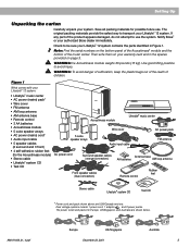
... the carton 5 Select the locations for your Lifestyle® 12 system 6 Connect the speakers and Lifestyle® music center 9 Connecting your home theater components to the Lifestyle® 12 system 12 Connect the antennas 16 Attach the wire cover 16 Set up the remote control 17 ...Adding speakers ...25 Troubleshooting ...26 Warranty period ...27 Customer service ...27 Cleaning the Lifestyle® 12 system 28 Product Information Technical information 29 Accessories ...29 Index ...30 Bose® Corporation inside back cover For your sales slip and warranty card together with this...
... the carton 5 Select the locations for your Lifestyle® 12 system 6 Connect the speakers and Lifestyle® music center 9 Connecting your home theater components to the Lifestyle® 12 system 12 Connect the antennas 16 Attach the wire cover 16 Set up the remote control 17 ...Adding speakers ...25 Troubleshooting ...26 Warranty period ...27 Customer service ...27 Cleaning the Lifestyle® 12 system 28 Product Information Technical information 29 Accessories ...29 Index ...30 Bose® Corporation inside back cover For your sales slip and warranty card together with this...
Owner's guide
Page 7
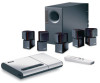
...). Check to avoid injury. Then write them on your system. Figure 1 What comes with your authorized Bose dealer immediately. Notify Bose® or your Lifestyle® 12 system: • Lifestyle® music center • AC power (mains) pack* • Wire cover • FM antenna • AM loop antenna • AM antenna base • Remote control •...
...). Check to avoid injury. Then write them on your system. Figure 1 What comes with your authorized Bose dealer immediately. Notify Bose® or your Lifestyle® 12 system: • Lifestyle® music center • AC power (mains) pack* • Wire cover • FM antenna • AM loop antenna • AM antenna base • Remote control •...
Owner's guide
Page 11
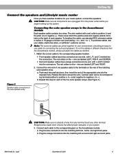
... splice in different directions from the Acoustimass module, simply pull apart the cables as needed. 1. Connect the wire end of one end, with L and R molded into the connectors. Connect each cable to negative (- ...your system. 3. The red collars on the rear of your dealer, electronics store, or call Bose® customer service. Bridged wires create short circuits that affect proper operation of the matching cube speaker array. CAUTION: Make sure... arrays to -). Setting Up Connect the speakers and Lifestyle® music center Once you begin hooking up the system.
... splice in different directions from the Acoustimass module, simply pull apart the cables as needed. 1. Connect the wire end of one end, with L and R molded into the connectors. Connect each cable to negative (- ...your system. 3. The red collars on the rear of your dealer, electronics store, or call Bose® customer service. Bridged wires create short circuits that affect proper operation of the matching cube speaker array. CAUTION: Make sure... arrays to -). Setting Up Connect the speakers and Lifestyle® music center Once you begin hooking up the system.
Owner's guide
Page 18
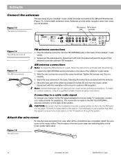
Unwind each antenna's wires. Figure 13 The antenna connections FM antenna AM antenna jack terminals ® LIFESTYLE ® MODEL 5 MUSIC CENTER B Z G642 950 D S T BOSE Corporation UL LISTED 917D AUDIO ® EQUIPMENT MANUFACTURED: TÜV Rheinland BOSE CORPORATION, FRAMINGHAM, MA 01701-9168 MADE IN USA gepr&#... Spread out the antenna arms. Experiment with the music center antenna connections. Slide the wire connectors around the screw terminals. Move the loop part of the Lifestyle® music center. 2. To install an outdoor antenna, consult a qualified installer. ...
Unwind each antenna's wires. Figure 13 The antenna connections FM antenna AM antenna jack terminals ® LIFESTYLE ® MODEL 5 MUSIC CENTER B Z G642 950 D S T BOSE Corporation UL LISTED 917D AUDIO ® EQUIPMENT MANUFACTURED: TÜV Rheinland BOSE CORPORATION, FRAMINGHAM, MA 01701-9168 MADE IN USA gepr&#... Spread out the antenna arms. Experiment with the music center antenna connections. Slide the wire connectors around the screw terminals. Move the loop part of the Lifestyle® music center. 2. To install an outdoor antenna, consult a qualified installer. ...
Owner's guide
Page 32
...16 cable TV 12 CD 4, 8, 12, 18, 19, 21, 22, 24, 26-28 CD player cover 8 CDI player 12, 20 center... 29 customer service 6, 9, 27 D display 12, 14, 18, 20-22, 24, 27 DVD 12, 15, 20, 22, 27 E enhanced ... H headphones 22, 26 house codes 17, 24, 25, 26 L laserdisc 12-14, 26 M moisture 2 movie soundtracks 20, 23 music center 2-5, 8-19... cable 5-9, 27 SURROUND 4, 14, 19, 20, 26 surround 4-7, 9, 10, 12, 19, 20, 26 surround (rear) speakers 7 surround cables 9 surround speakers 4,...tuning 6, 21, 23 turntable 15 TV 4, 6-8, 12-14, 16, 26, 27 U unpack 3, 5 V VCR 8, 12-14, 26, 27 ventilation 8 VIDEO SOUND jack ...
...16 cable TV 12 CD 4, 8, 12, 18, 19, 21, 22, 24, 26-28 CD player cover 8 CDI player 12, 20 center... 29 customer service 6, 9, 27 D display 12, 14, 18, 20-22, 24, 27 DVD 12, 15, 20, 22, 27 E enhanced ... H headphones 22, 26 house codes 17, 24, 25, 26 L laserdisc 12-14, 26 M moisture 2 movie soundtracks 20, 23 music center 2-5, 8-19... cable 5-9, 27 SURROUND 4, 14, 19, 20, 26 surround 4-7, 9, 10, 12, 19, 20, 26 surround (rear) speakers 7 surround cables 9 surround speakers 4,...tuning 6, 21, 23 turntable 15 TV 4, 6-8, 12-14, 16, 26, 27 U unpack 3, 5 V VCR 8, 12-14, 26, 27 ventilation 8 VIDEO SOUND jack ...

