Owner's guide
Page 3
... other sources 15 Other component connections 15 Connecting your TV to the system 16 Connecting your VCR to the system 16 Attaching the supplied antennas 17 Connecting cable FM radio 18 Make the power connection after all the others 18 Turning off the internal speakers in your TV 18 Installing remote control...
... other sources 15 Other component connections 15 Connecting your TV to the system 16 Connecting your VCR to the system 16 Attaching the supplied antennas 17 Connecting cable FM radio 18 Make the power connection after all the others 18 Turning off the internal speakers in your TV 18 Installing remote control...
Owner's guide
Page 8
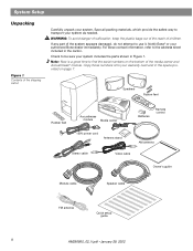
... center Batteries Remote control 120V power cord Antenna stand AM antenna Stereo cable Video cable Owner's guide Module cable Speaker cable FM antenna Quick setup guide 8 AM256950_02_V.pdf • January 29, 2002 Check to be sure your authorized Bose dealer immediately. For Bose contact information, refer to use it. Notify Bose® or your system includes the...
... center Batteries Remote control 120V power cord Antenna stand AM antenna Stereo cable Video cable Owner's guide Module cable Speaker cable FM antenna Quick setup guide 8 AM256950_02_V.pdf • January 29, 2002 Check to be sure your authorized Bose dealer immediately. For Bose contact information, refer to use it. Notify Bose® or your system includes the...
Owner's guide
Page 13
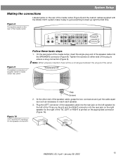
... Model 3•2•1 system make it ) and the RIGHT connector into the rear jack on the rear of the media center VIDEO 1 D L 75 Ω FM AM LOOP ANTENNA ANTENNA OPTICAL R AUDIO INPUT VIDEO 2 L D R D AUX L VIDEO INPUT C VIDEO OUTPUT C AUDIO OUTPUT L R S S R SPEAKERS ACOUSTIMASS MODULE Figure 9 Completed connection of speaker cable to the right of...
... Model 3•2•1 system make it ) and the RIGHT connector into the rear jack on the rear of the media center VIDEO 1 D L 75 Ω FM AM LOOP ANTENNA ANTENNA OPTICAL R AUDIO INPUT VIDEO 2 L D R D AUX L VIDEO INPUT C VIDEO OUTPUT C AUDIO OUTPUT L R S S R SPEAKERS ACOUSTIMASS MODULE Figure 9 Completed connection of speaker cable to the right of...
Owner's guide
Page 14
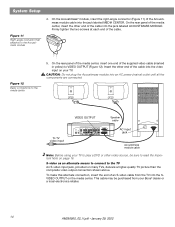
RIGHT LEFT To TV video input VIDEO OUTPUT Speaker cable VIDEO D L 75 Ω FM AM LOOP ANTENNA ANTENNA OPTICAL R AUDIO INPUT IDEO 2 L D R D AUX L VIDEO INPUT C VIDEO OUTPUT C AUDIO OUTPUT L SPEAKERS R S ACOUSTIMASS MODULE S R AC input jack AC INPUT MUSIC CENTER ... page 16. On the Acoustimass® module, insert the right-angle connector (Figure 11) of the cable into the SVIDEO OUTPUT on your Bose® dealer or a local electronics retailer. 14 AM256950_02_V.pdf • January 29, 2002 Insert the other end of the Acoustimass module cable into...
RIGHT LEFT To TV video input VIDEO OUTPUT Speaker cable VIDEO D L 75 Ω FM AM LOOP ANTENNA ANTENNA OPTICAL R AUDIO INPUT IDEO 2 L D R D AUX L VIDEO INPUT C VIDEO OUTPUT C AUDIO OUTPUT L SPEAKERS R S ACOUSTIMASS MODULE S R AC input jack AC INPUT MUSIC CENTER ... page 16. On the Acoustimass® module, insert the right-angle connector (Figure 11) of the cable into the SVIDEO OUTPUT on your Bose® dealer or a local electronics retailer. 14 AM256950_02_V.pdf • January 29, 2002 Insert the other end of the Acoustimass module cable into...
Owner's guide
Page 16
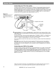
For most TV models*, there is available at your VCR does not have neither a composite video nor an S-Video input. VIDEO 1 D L 75 Ω FM AM LOOP ANTENNA ANTENNA OPTICAL R AUDIO INPUT VIDEO 2 L D R D AUX L VIDEO INPUT C VIDEO OUTPUT C AUDIO OUTPUT L SPEAKERS R S ACOUSTIMASS MODULE S R Media center VIDEO IN AUDIO OUT L R TV Supplied video cable TV/...
For most TV models*, there is available at your VCR does not have neither a composite video nor an S-Video input. VIDEO 1 D L 75 Ω FM AM LOOP ANTENNA ANTENNA OPTICAL R AUDIO INPUT VIDEO 2 L D R D AUX L VIDEO INPUT C VIDEO OUTPUT C AUDIO OUTPUT L SPEAKERS R S ACOUSTIMASS MODULE S R Media center VIDEO IN AUDIO OUT L R TV Supplied video cable TV/...

Owner's guide
Page 17
... VCR to the composite video input on the supplied base, or mount it on the media center Figure 16 Adding the AM and FM antennas VIDEO 1 D L 75 Ω AM FM LOOP ANTENNA ANTENNA OPTICAL R AUDIO INPUT VIDEO 2 L D R D AUX L VIDEO INPUT C VIDEO AUDIO OUTPUT OUTPUT C L SPEAKERS R S ACOUSTIMASS MODULE S R Media center VIDEO OUT AUDIO OUT Video cable...
... VCR to the composite video input on the supplied base, or mount it on the media center Figure 16 Adding the AM and FM antennas VIDEO 1 D L 75 Ω AM FM LOOP ANTENNA ANTENNA OPTICAL R AUDIO INPUT VIDEO 2 L D R D AUX L VIDEO INPUT C VIDEO AUDIO OUTPUT OUTPUT C L SPEAKERS R S ACOUSTIMASS MODULE S R Media center VIDEO OUT AUDIO OUT Video cable...
Owner's guide
Page 20
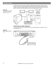
..., VIDEO 1) on your remote to select the sound from any video program you to the media center. This allows you play. VIDEO I D L 75 Ω AM FM LOOP ANTENNA ANTENNA OPTICAL R AUDIO INPUT VIDEO 2 L D AUX L VIDEO INPUT C VIDEO OUTPUT C AUDIO OUTPUT L SPEAKERS R D R S S R ACOUSTIMASS MODULE RECORD INPUT Media center L R Recording component 20 AM256950_02_V.pdf •...
..., VIDEO 1) on your remote to select the sound from any video program you to the media center. This allows you play. VIDEO I D L 75 Ω AM FM LOOP ANTENNA ANTENNA OPTICAL R AUDIO INPUT VIDEO 2 L D AUX L VIDEO INPUT C VIDEO OUTPUT C AUDIO OUTPUT L SPEAKERS R D R S S R ACOUSTIMASS MODULE RECORD INPUT Media center L R Recording component 20 AM256950_02_V.pdf •...
Owner's guide
Page 21
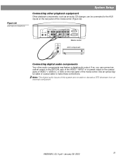
... optical digital cable or coaxial cable to decode a DTS bitstream from an external component. AM256950_02_V.pdf • January 29, 2002 21 VIDEO I D L 75 Ω AM FM LOOP ANTENNA ANTENNA OPTICAL R AUDIO INPUT VIDEO 2 L D R D AUX L VIDEO INPUT C VIDEO AUDIO OUTPUT OUTPUT C L R S S R SPEAKERS ACOUSTIMASS MODULE Media center AUDIO OUT AUX component L R Connecting digital audio components...
... optical digital cable or coaxial cable to decode a DTS bitstream from an external component. AM256950_02_V.pdf • January 29, 2002 21 VIDEO I D L 75 Ω AM FM LOOP ANTENNA ANTENNA OPTICAL R AUDIO INPUT VIDEO 2 L D R D AUX L VIDEO INPUT C VIDEO AUDIO OUTPUT OUTPUT C L R S S R SPEAKERS ACOUSTIMASS MODULE Media center AUDIO OUT AUX component L R Connecting digital audio components...
Owner's guide
Page 39
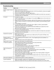
...38. Clean the disc. See "Cleaning discs" on page 38. • The disc may be in the CD tray. • Connect the FM and AM antennas. • Unplug the Acoustimass module power cord from the outlet for a minute, then reconnect it is • Check batteries and their polarity ...on the other electronic equipment. • You may be upright. • Move antennas farther from the media center. • Adjust antenna position to reset itself . This allows the unit to select a source (CD/DVD, AM/FM, etc.). • Unplug the Acoustimass module power cord from any external components....
...38. Clean the disc. See "Cleaning discs" on page 38. • The disc may be in the CD tray. • Connect the FM and AM antennas. • Unplug the Acoustimass module power cord from the outlet for a minute, then reconnect it is • Check batteries and their polarity ...on the other electronic equipment. • You may be upright. • Move antennas farther from the media center. • Adjust antenna position to reset itself . This allows the unit to select a source (CD/DVD, AM/FM, etc.). • Unplug the Acoustimass module power cord from any external components....


