
TForce 6100 user's manual
Page 1
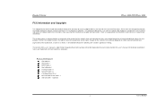
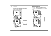
... CHECKLIST FDD Cable x 1 HDD Cable x 1 SPDIF Cable x 1 User's Manual x 1 Overclock Guide x 1 Serial ATA Cable x 2 Fully Setup Driver CD x 1 Rear I/O Panel for any party beforehand. Biostar T-Series TForce 6100-939/ TForce 6100 FCC Information and Copyright This equipment has been tested and found in this publication, in part or in whole, is not allowed without first...
... CHECKLIST FDD Cable x 1 HDD Cable x 1 SPDIF Cable x 1 User's Manual x 1 Overclock Guide x 1 Serial ATA Cable x 2 Fully Setup Driver CD x 1 Rear I/O Panel for any party beforehand. Biostar T-Series TForce 6100-939/ TForce 6100 FCC Information and Copyright This equipment has been tested and found in this publication, in part or in whole, is not allowed without first...
TForce 6100 user's manual
Page 2
...(CPU) for Socket 939...1 B. Memory Space...3 C. Card and I CHAPTER 1: INTRODUCTION ...1 1.1 MOTHERBOARD FEATURES ...1 1.2 LAYOUT AND COMPONENTS: TFORCE 6100-939...2 1.3 LAYOUT AND COMPONENTS: TFORCE 6100 ...3 CHAPTER 2: HARDWARE INSTALLATIONS ...1 2.1 CPU ASSEMBLY ...1 A. Central Processing Unit (CPU) for Socket 754...1 C. DDR Installation Notice...3 D. ...22 ii User's Manual Know your CPU version ...3 2.3 PERIPHERALS ...4 A. Biostar T-Series TForce 6100-939/ TForce 6100 PACKAGE CHECKLIST ...I /O Slots:...4 B. About FAN Headers ...2 2.2 SYSTEM MEMORY...2 A.
...(CPU) for Socket 939...1 B. Memory Space...3 C. Card and I CHAPTER 1: INTRODUCTION ...1 1.1 MOTHERBOARD FEATURES ...1 1.2 LAYOUT AND COMPONENTS: TFORCE 6100-939...2 1.3 LAYOUT AND COMPONENTS: TFORCE 6100 ...3 CHAPTER 2: HARDWARE INSTALLATIONS ...1 2.1 CPU ASSEMBLY ...1 A. Central Processing Unit (CPU) for Socket 754...1 C. DDR Installation Notice...3 D. ...22 ii User's Manual Know your CPU version ...3 2.3 PERIPHERALS ...4 A. Biostar T-Series TForce 6100-939/ TForce 6100 PACKAGE CHECKLIST ...I /O Slots:...4 B. About FAN Headers ...2 2.2 SYSTEM MEMORY...2 A.
TForce 6100 user's manual
Page 3
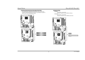
... Dimensions Micro ATX Form Factor: 24.5cm (W) x 24.45cm (L) Main Memory Supports Dual Channel DDR. Supports DDR 266/333/400. TForce 6100-939/ TForce 6100 Chipset North Bridge: NVIDIA Geforce6100. Super I /O Connectors and Ports 4 USB 2.0 Ports. 1 VGA Port. 1 Serial Port. 1 ... slot. Two SATA ports. Back Panel I /O Chip: ITE IT8712F. Biostar T-Series Chapter 1: Introduction 1.1 MOTHERBOARD FEATURES TForce 6100-939 CPU Supports Socket 939. Two PCI slots. TForce 6100 CPU Supports Socket 754. Supports HyperTransport Technology up to 1600MT/s. Dimensions Micro ATX...
... Dimensions Micro ATX Form Factor: 24.5cm (W) x 24.45cm (L) Main Memory Supports Dual Channel DDR. Supports DDR 266/333/400. TForce 6100-939/ TForce 6100 Chipset North Bridge: NVIDIA Geforce6100. Super I /O Connectors and Ports 4 USB 2.0 Ports. 1 VGA Port. 1 Serial Port. 1 ... slot. Two SATA ports. Back Panel I /O Chip: ITE IT8712F. Biostar T-Series Chapter 1: Introduction 1.1 MOTHERBOARD FEATURES TForce 6100-939 CPU Supports Socket 939. Two PCI slots. TForce 6100 CPU Supports Socket 754. Supports HyperTransport Technology up to 1600MT/s. Dimensions Micro ATX...
TForce 6100 user's manual
Page 4
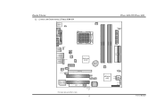
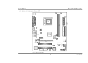
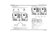
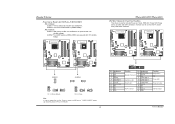
Biostar T-Series 1.2 LAYOUT AND COMPONENTS: TFORCE 6100-939 JKBMS1 JKBV1 J CFAN 1 CPU1 TForce 6100-939/ TForce 6100 J DDR _0V> 3V JCOM1 Socket 939 JPRNT1 DIMMB1 DIMMB2 DIMMA1 DIMMA2 JVGA1 JUSB1 JUS BV1 JATXPWR2 JUSBLAN1 JAUDIO1 JAUDIO2 LAN PHY JNFAN1 J CD IN1 PCI-EX1_1 GeForce 6100 BAT1 Codec JSPDIF_O UT1 PCI-EX16 PCI1 J US BV2 JUS B2 JUSB3 Super I/O PCI2...
Biostar T-Series 1.2 LAYOUT AND COMPONENTS: TFORCE 6100-939 JKBMS1 JKBV1 J CFAN 1 CPU1 TForce 6100-939/ TForce 6100 J DDR _0V> 3V JCOM1 Socket 939 JPRNT1 DIMMB1 DIMMB2 DIMMA1 DIMMA2 JVGA1 JUSB1 JUS BV1 JATXPWR2 JUSBLAN1 JAUDIO1 JAUDIO2 LAN PHY JNFAN1 J CD IN1 PCI-EX1_1 GeForce 6100 BAT1 Codec JSPDIF_O UT1 PCI-EX16 PCI1 J US BV2 JUS B2 JUSB3 Super I/O PCI2...
TForce 6100 user's manual
Page 5
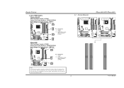
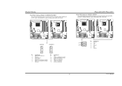
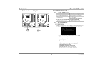
Biostar T-Series 1.3 LAYOUT AND COMPONENTS: TFORCE 6100 JKBMS1 TForce 6100-939/ TForce 6100 JCFAN1 J SFAN 2 J DD R_0V> 3V JCOM1 Socket 754 JPRNT1 JVGA1 JUSB1 JUS BV1 JATXPWR2 CPU1 DIMM2 DIMM1 JATXPWR1 L ED _D 1 L ED _D 2 L ED_DI MM L ED_P W R IDE1 IDE2 JUSBLAN1 JAUDIO1 J FAU D IO1 LAN PHY PCI-EX1_1 JCD I N1 Codec JSPDIF_O UT1 GeForce 6100 JNB FAN1 BAT1 PCI-EX16 JSFAN1 RSTSW2 PW R SW 1 PCI1 Super I/O PCI2 FDD1 Note: ■ represents the 1st pin. JUS B3 JUS BV2 JUS B2 BIOS nForce 410 JSATA 2 JSATA 1 JCI1 JCMOS 1 J PANEL 1 3 User's Manual
Biostar T-Series 1.3 LAYOUT AND COMPONENTS: TFORCE 6100 JKBMS1 TForce 6100-939/ TForce 6100 JCFAN1 J SFAN 2 J DD R_0V> 3V JCOM1 Socket 754 JPRNT1 JVGA1 JUSB1 JUS BV1 JATXPWR2 CPU1 DIMM2 DIMM1 JATXPWR1 L ED _D 1 L ED _D 2 L ED_DI MM L ED_P W R IDE1 IDE2 JUSBLAN1 JAUDIO1 J FAU D IO1 LAN PHY PCI-EX1_1 JCD I N1 Codec JSPDIF_O UT1 GeForce 6100 JNB FAN1 BAT1 PCI-EX16 JSFAN1 RSTSW2 PW R SW 1 PCI1 Super I/O PCI2 FDD1 Note: ■ represents the 1st pin. JUS B3 JUS BV2 JUS B2 BIOS nForce 410 JSATA 2 JSATA 1 JCI1 JCMOS 1 J PANEL 1 3 User's Manual
TForce 6100 user's manual
Page 6
...angle. The CPU will fit only in the correct orientation. Connect the CPU FAN power cable into the JCFAN1. B. This completes the installation. Biostar T-Series Chapter 2: Hardware Installations 2.1 CPU ASSEMBLY A. This completes the installation. 1 User's Manual The CPU will fit only in the correct...retention frame. Step 4: Hold the CPU down firmly, and then lower the lever to locked position to complete the installation. TForce 6100-939/ TForce 6100 Step 5: Put the CPU Fan and heatsink assembly on the CPU and buckle it on CPU should point towards this triangular cut...
...angle. The CPU will fit only in the correct orientation. Connect the CPU FAN power cable into the JCFAN1. B. This completes the installation. Biostar T-Series Chapter 2: Hardware Installations 2.1 CPU ASSEMBLY A. This completes the installation. 1 User's Manual The CPU will fit only in the correct...retention frame. Step 4: Hold the CPU down firmly, and then lower the lever to locked position to complete the installation. TForce 6100-939/ TForce 6100 Step 5: Put the CPU Fan and heatsink assembly on the CPU and buckle it on CPU should point towards this triangular cut...
TForce 6100 user's manual
Page 7
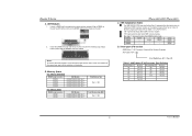
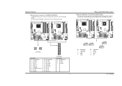
Biostar T-Series C. About FAN Headers TForce 6100-939 CPU Fan Power Header: JCFAN1 System Fan Power Headers: JSFAN1/JSFAN2 North Bridge Fan Power Header: JNFAN1 JCFAN1 31 JNFAN1 3 Pin Assignment 1 1 Ground 2 +12V 3 FAN RPM rate sense JSFAN1 (Does not support JSFAN2.) 13 JSFAN2 3 1 TForce 6100 CPU...#2, and the black wire is Ground and should be connected to GND. 2.2 SYSTEM MEMORY TForce 6100-939 2 DIMMB2 DIMMB1 DIMMA2 DIMMA1 DIMMB2 DIMMB1 TForce 6100-939/ TForce 6100 TForce 6100 User's Manual When connecting with Smart Fan Control utilities. It supports 3 pin head connector.
Biostar T-Series C. About FAN Headers TForce 6100-939 CPU Fan Power Header: JCFAN1 System Fan Power Headers: JSFAN1/JSFAN2 North Bridge Fan Power Header: JNFAN1 JCFAN1 31 JNFAN1 3 Pin Assignment 1 1 Ground 2 +12V 3 FAN RPM rate sense JSFAN1 (Does not support JSFAN2.) 13 JSFAN2 3 1 TForce 6100 CPU...#2, and the black wire is Ground and should be connected to GND. 2.2 SYSTEM MEMORY TForce 6100-939 2 DIMMB2 DIMMB1 DIMMA2 DIMMA1 DIMMB2 DIMMB1 TForce 6100-939/ TForce 6100 TForce 6100 User's Manual When connecting with Smart Fan Control utilities. It supports 3 pin head connector.
TForce 6100 user's manual
Page 8
Biostar T-Series A. Notes: To remove the DDR modules, push the ejector tabs at both...Part Definition BN BP BO BY BW Revision Rev E4 Rev E3 Rev E3 Rev E6 Rev E6 3 User's Manual TForce 6100-939/ TForce 6100 C. DDR Installation Notice For AMD K8 939 CPU launched before Rev. "DS" represents Double Side DDR memory module....Revision) "SS" represents Single Side DDR memory module. Star sign "*" represents leave the DIMM socket empty. Memory Space For TForce 6100-939 DIMM Socket Location DIMMA1 DIMMA2 DIMMB1 DIMMB2 DDR Module 128MB/256MB/512MB/1GB *1 128MB/256MB/512MB/1GB *1 128MB/256MB/...
Biostar T-Series A. Notes: To remove the DDR modules, push the ejector tabs at both...Part Definition BN BP BO BY BW Revision Rev E4 Rev E3 Rev E3 Rev E6 Rev E6 3 User's Manual TForce 6100-939/ TForce 6100 C. DDR Installation Notice For AMD K8 939 CPU launched before Rev. "DS" represents Double Side DDR memory module....Revision) "SS" represents Single Side DDR memory module. Star sign "*" represents leave the DIMM socket empty. Memory Space For TForce 6100-939 DIMM Socket Location DIMMA1 DIMMA2 DIMMB1 DIMMB2 DDR Module 128MB/256MB/512MB/1GB *1 128MB/256MB/512MB/1GB *1 128MB/256MB/...
TForce 6100 user's manual
Page 9
... hard drive should always be connected to four hard disk drives. TForce 6100-939 TForce 6100-939/ TForce 6100 Hard Disk Connectors: IDE1/IDE2 The motherboard has two 32-bit Enhanced PCI IDE Controllers that supports 360K, 720K, 1.2M, 1.44M and 2.88M floppy disk types. Biostar T-Series 2.3 PERIPHERALS A. It has two HDD connectors IDE1 (primary) and IDE2...
... hard drive should always be connected to four hard disk drives. TForce 6100-939 TForce 6100-939/ TForce 6100 Hard Disk Connectors: IDE1/IDE2 The motherboard has two 32-bit Enhanced PCI IDE Controllers that supports 360K, 720K, 1.2M, 1.44M and 2.88M floppy disk types. Biostar T-Series 2.3 PERIPHERALS A. It has two HDD connectors IDE1 (primary) and IDE2...
TForce 6100 user's manual
Page 10
.... - PCI-EX1_1: - Maximum bandwidth is up to 250MB/s per direction. Biostar T-Series Peripheral Component Interconnect Slots: PCI1~PCI2 This motherboard is designated as 32 bits. TForce 6100-939 TForce 6100 PCI1 PCI2 TForce 6100 PCI-EX1_1 PCI-EX16 5 User's Manual PCI Express 1.0a compliant. - TForce 6100-939 TForce 6100-939/ TForce 6100 PCI-Express Slots PCI-EX16: - PCI stands for expansion cards. Maximum...
.... - PCI-EX1_1: - Maximum bandwidth is up to 250MB/s per direction. Biostar T-Series Peripheral Component Interconnect Slots: PCI1~PCI2 This motherboard is designated as 32 bits. TForce 6100-939 TForce 6100 PCI1 PCI2 TForce 6100 PCI-EX1_1 PCI-EX16 5 User's Manual PCI Express 1.0a compliant. - TForce 6100-939 TForce 6100-939/ TForce 6100 PCI-Express Slots PCI-EX16: - PCI stands for expansion cards. Maximum...
TForce 6100 user's manual
Page 11
... OFF OFF CPU / Chipset Error LED_DIMM: This LED indicates the voltage of memory is "closed . TForce 6100-939/ TForce 6100 LED Indicators and Buttons There are 4 LED indicators on . TForce 6100-939 TForce 6100 JDDR_OV>3V 13 13 31 31 13 31 Pin 1-2 Close Pin 2-3 Close (Default) Note: 1....Reset button. Please refer to the table below for Power-on the motherboard to 3V. (Consulting your DDR supports up jumpers. Biostar T-Series B. The default setting is placed on diagnostics. Before setting memory voltage overclocking, please ensure that means the jumper is...
... OFF OFF CPU / Chipset Error LED_DIMM: This LED indicates the voltage of memory is "closed . TForce 6100-939/ TForce 6100 LED Indicators and Buttons There are 4 LED indicators on . TForce 6100-939 TForce 6100 JDDR_OV>3V 13 13 31 31 13 31 Pin 1-2 Close Pin 2-3 Close (Default) Note: 1....Reset button. Please refer to the table below for Power-on the motherboard to 3V. (Consulting your DDR supports up jumpers. Biostar T-Series B. The default setting is placed on diagnostics. Before setting memory voltage overclocking, please ensure that means the jumper is...
TForce 6100 user's manual
Page 12
... By connecting JATXPWR2, it will provide +12V to connect additional USB cables at Front Panel: JUSB2~JUSB3 This connector allows user to CPU power circuit. TForce 6100-939 TForce 6100 11 24 4 3 1 4 1 2 2 3 JATXPWR2 JATXPWR1: Pin Assignment Pin Assignment 1 +3.3V 13 +3.3V 2 +3.3V 14 -12V ...3 USB- 4 USB- 5 USB+ JUSB3 10 9 Pin Assignment 6 USB+ 7 Ground 8 Ground 9 Key 10 NC JUSB3 2 1 JUSB2 10 9 User's Manual Biostar T-Series ATX Power Source Connectors: JATXPWR1/JATXPWR2 JATXPWR1 allows user to connect 24-pin power connector on the ATX power supply.
... By connecting JATXPWR2, it will provide +12V to connect additional USB cables at Front Panel: JUSB2~JUSB3 This connector allows user to CPU power circuit. TForce 6100-939 TForce 6100 11 24 4 3 1 4 1 2 2 3 JATXPWR2 JATXPWR1: Pin Assignment Pin Assignment 1 +3.3V 13 +3.3V 2 +3.3V 14 -12V ...3 USB- 4 USB- 5 USB+ JUSB3 10 9 Pin Assignment 6 USB+ 7 Ground 8 Ground 9 Key 10 NC JUSB3 2 1 JUSB2 10 9 User's Manual Biostar T-Series ATX Power Source Connectors: JATXPWR1/JATXPWR2 JATXPWR1 allows user to connect 24-pin power connector on the ATX power supply.
TForce 6100 user's manual
Page 13
... at JUSB1 and JUSBLAN1. TForce 6100-939 TForce 6100 TForce 6100-939/ TForce 6100 JPANEL1: Header for Front Panel Facilities This 24-pin connector includes Power-on button IrDA Connector User's Manual TForce 6100-939 TForce 6100 JUSBV1 1 3 JUSBV2 31... 13 1 31 3 13 Pin 1-2 Close (Default) 1 31 3 Pin 2-3 Close 13 Note: In order to connect the PC case's front panel switch functions. JUSBV2: Front USB headers (JUSB2/JUSB3) are powered with +5V standby voltage. JUSBV2: +5V for front USB headers (JUSB2/JUSB3). Biostar...
... at JUSB1 and JUSBLAN1. TForce 6100-939 TForce 6100 TForce 6100-939/ TForce 6100 JPANEL1: Header for Front Panel Facilities This 24-pin connector includes Power-on button IrDA Connector User's Manual TForce 6100-939 TForce 6100 JUSBV1 1 3 JUSBV2 31... 13 1 31 3 13 Pin 1-2 Close (Default) 1 31 3 Pin 2-3 Close 13 Note: In order to connect the PC case's front panel switch functions. JUSBV2: Front USB headers (JUSB2/JUSB3) are powered with +5V standby voltage. JUSBV2: +5V for front USB headers (JUSB2/JUSB3). Biostar...
TForce 6100 user's manual
Page 14
TForce 6100-939 TForce 6100 JAUDIO2 1 JFAUDIO1 2 13 Pin Assignment 1 MIC-in/ Stereo MIC-in R 2 Ground 3 Stereo MIC-in L 4 Audio power 5 Right line-out/ Speaker-out Right 6 Right line-out/ ... the front audio output headers on back panel audio connectors. Biostar T-Series Front Panel Audio-out Header: JAUDIO2/JFAUDIO1 This connector will disable the output on the PC case. It will allow user to connect with transfer rate of 3.0 Gb/s. TForce 6100-939 TForce 6100 TForce 6100-939/ TForce 6100 Serial ATA Connectors: JSATA1~JSATA2 The motherboard has an...
TForce 6100-939 TForce 6100 JAUDIO2 1 JFAUDIO1 2 13 Pin Assignment 1 MIC-in/ Stereo MIC-in R 2 Ground 3 Stereo MIC-in L 4 Audio power 5 Right line-out/ Speaker-out Right 6 Right line-out/ ... the front audio output headers on back panel audio connectors. Biostar T-Series Front Panel Audio-out Header: JAUDIO2/JFAUDIO1 This connector will disable the output on the PC case. It will allow user to connect with transfer rate of 3.0 Gb/s. TForce 6100-939 TForce 6100 TForce 6100-939/ TForce 6100 Serial ATA Connectors: JSATA1~JSATA2 The motherboard has an...
TForce 6100 user's manual
Page 15
... Pin 2-3 Close: PS/2 keyboard and mouse are powered with +5V standby voltage. Set the jumper to "Pin 1-2 Close". 5. TForce 6100-939/ TForce 6100 Power Source Header for PS/2 Keyboard/Mouse: JKBV1 Pin 1-2 Close: +5V for five seconds. 4. Reset your desired password or clear ... the CMOS data, please carefully follow the procedures to avoid damaging the motherboard. Biostar T-Series Clear CMOS Header: JCMOS1 By placing the jumper on Pin 2-3. 10 User's Manual Set the jumper to "Pin 2-3 Close". 3. TForce 6100-939 TForce 6100 JCMOS1 1 3 1 3 Pin 1-2 Close Normal Operation (Default). 1 3 ...
... Pin 2-3 Close: PS/2 keyboard and mouse are powered with +5V standby voltage. Set the jumper to "Pin 1-2 Close". 5. TForce 6100-939/ TForce 6100 Power Source Header for PS/2 Keyboard/Mouse: JKBV1 Pin 1-2 Close: +5V for five seconds. 4. Reset your desired password or clear ... the CMOS data, please carefully follow the procedures to avoid damaging the motherboard. Biostar T-Series Clear CMOS Header: JCMOS1 By placing the jumper on Pin 2-3. 10 User's Manual Set the jumper to "Pin 2-3 Close". 3. TForce 6100-939 TForce 6100 JCMOS1 1 3 1 3 Pin 1-2 Close Normal Operation (Default). 1 3 ...
TForce 6100 user's manual
Page 16
...PCI sound card, PCI TV tuner card etc.. Biostar T-Series CD-ROM Audio-in Connector: JCDIN1 This connector allows user to the CMOS and show the message on next boot-up. TForce 6100-939 TForce 6100 TForce 6100-939/ TForce 6100 Case Open Header: JCI1 This connector allows system ...to monitor PC case open signal 2 Ground 11 User's Manual TForce 6100-939 TForce 6100 JCDIN1 1 4 Pin Assignment 1 Left channel input 2 Ground 3...
...PCI sound card, PCI TV tuner card etc.. Biostar T-Series CD-ROM Audio-in Connector: JCDIN1 This connector allows user to the CMOS and show the message on next boot-up. TForce 6100-939 TForce 6100 TForce 6100-939/ TForce 6100 Case Open Header: JCI1 This connector allows system ...to monitor PC case open signal 2 Ground 11 User's Manual TForce 6100-939 TForce 6100 JCDIN1 1 4 Pin Assignment 1 Left channel input 2 Ground 3...
TForce 6100 user's manual
Page 17
... Flash Utility "AWDFLASH.exe" from Biostar website. 4. Copy "AWDFLASH.exe" and respective BIOS onto floppy disk. 5. System will shut down automatically One Short beep when system boots-up of the system, it means the BIOS contents are corrupted. TForce 6100-939 TForce 6100 JSPDIF_OUT 3 1 Pin Assignment 1 +5V 2 SPDIF OUT 3 Ground TForce 6100-939/ TForce 6100 CHAPTER 3: USEFUL HELP 3.1 AWARD...
... Flash Utility "AWDFLASH.exe" from Biostar website. 4. Copy "AWDFLASH.exe" and respective BIOS onto floppy disk. 5. System will shut down automatically One Short beep when system boots-up of the system, it means the BIOS contents are corrupted. TForce 6100-939 TForce 6100 JSPDIF_OUT 3 1 Pin Assignment 1 +5V 2 SPDIF OUT 3 Ground TForce 6100-939/ TForce 6100 CHAPTER 3: USEFUL HELP 3.1 AWARD...
TForce 6100 user's manual
Page 18
...section) 2. No power to relieve the CPU protection function. 1. Backing up the system. can be booted from hard disk 1. TForce 6100-939/ TForce 6100 3.3 TROUBLESHOOTING Problem Solution 1. Replace cable. Hard disk can be used but booting from optical drive. 1. Back up data and ... is securely Power light don't illuminate, fan plugged in the standard CMOS setup. Wait for compatibility with the CPU surface. 2. Biostar T-Series B. When the CPU is impossible. Or you can be read and applications 2. inside power supply does not 2. turn ...
...section) 2. No power to relieve the CPU protection function. 1. Backing up the system. can be booted from hard disk 1. TForce 6100-939/ TForce 6100 3.3 TROUBLESHOOTING Problem Solution 1. Replace cable. Hard disk can be used but booting from optical drive. 1. Back up data and ... is securely Power light don't illuminate, fan plugged in the standard CMOS setup. Wait for compatibility with the CPU surface. 2. Biostar T-Series B. When the CPU is impossible. Or you can be read and applications 2. inside power supply does not 2. turn ...


