Setup Manual
Page 4
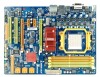
... compliant. RAID 0,1,5,1+0 support LAN Realtek RTL 8111DL 10 / 100 Mb/s / 1Gb/s auto negotiation Half / Full duplex capability Sound ALC888 7.1channels audio out Supports HD Audio 2 Motherboard Manual 1.3 MOTHERBOARD FEATURES SPEC Socket AM2+ / AM3 AMD 64 Architecture enables 32 and 64 bit CPU AMD Athlon 64 / Athlon 64 FX / Athlon 64 x2 computing / Sempron...
... compliant. RAID 0,1,5,1+0 support LAN Realtek RTL 8111DL 10 / 100 Mb/s / 1Gb/s auto negotiation Half / Full duplex capability Sound ALC888 7.1channels audio out Supports HD Audio 2 Motherboard Manual 1.3 MOTHERBOARD FEATURES SPEC Socket AM2+ / AM3 AMD 64 Architecture enables 32 and 64 bit CPU AMD Athlon 64 / Athlon 64 FX / Athlon 64 x2 computing / Sempron...

Setup Manual
Page 6
... different display panels simultaneously. 4 The chipset uses the same channel to control HDMI and DVI-D, so these two interfaces cannot work at the same time. Motherboard Manual 1.4 REAR PANEL CONNECTORS X PS/2 Mouse Port Y PS/2 Keyboard Port Z HDMI Port The High-Definition Multimedia Interface (HDMI) is a video interface transmitting digital video signals to...
... different display panels simultaneously. 4 The chipset uses the same channel to control HDMI and DVI-D, so these two interfaces cannot work at the same time. Motherboard Manual 1.4 REAR PANEL CONNECTORS X PS/2 Mouse Port Y PS/2 Keyboard Port Z HDMI Port The High-Definition Multimedia Interface (HDMI) is a video interface transmitting digital video signals to...

Setup Manual
Page 8
Motherboard Manual CHAPTER 2: HARDWARE INSTALLATION 2.1 INSTALLING CENTRAL PROCESSING UNIT (CPU) Step 1: Remove the socket protection cap. Step 3: Look for the white triangle on socket, and the gold triangle on CPU should point towards this white triangle. The CPU will fit only in the correct orientation. 6 Step 2: Pull the lever toward direction A from the socket and then raise the lever up to a 90-degree angle.
Motherboard Manual CHAPTER 2: HARDWARE INSTALLATION 2.1 INSTALLING CENTRAL PROCESSING UNIT (CPU) Step 1: Remove the socket protection cap. Step 3: Look for the white triangle on socket, and the gold triangle on CPU should point towards this white triangle. The CPU will fit only in the correct orientation. 6 Step 2: Pull the lever toward direction A from the socket and then raise the lever up to a 90-degree angle.

Setup Manual
Page 10
... Headers SYS_FAN1 Pin Assignment 1 Ground 2 +12V 3 FAN RPM rate sense 13 SYS_ FAN 2 Note: The CPU_FAN1, SYS_FAN1, and SYS_FAN2 support 4-pin and 3-pin head connectors. Motherboard Manual 2.2 FAN HEADERS These fan headers support cooling-fans built in the computer.
... Headers SYS_FAN1 Pin Assignment 1 Ground 2 +12V 3 FAN RPM rate sense 13 SYS_ FAN 2 Note: The CPU_FAN1, SYS_FAN1, and SYS_FAN2 support 4-pin and 3-pin head connectors. Motherboard Manual 2.2 FAN HEADERS These fan headers support cooling-fans built in the computer.

Setup Manual
Page 12
.../512MB/1GB/2GB/4GB 256MB/512MB/1GB/2GB/4GB 256MB/512MB/1GB/2GB/4GB 256MB/512MB/1GB/2GB/4GB Total Memory Size Max is 16GB. C. Motherboard Manual B.
.../512MB/1GB/2GB/4GB 256MB/512MB/1GB/2GB/4GB 256MB/512MB/1GB/2GB/4GB 256MB/512MB/1GB/2GB/4GB Total Memory Size Max is 16GB. C. Motherboard Manual B.

Setup Manual
Page 14
Pin Assignment 1 4 1 +12V 2 Ground 3 Ground 4 VCC 12 Exclusive power for graphics cards. SATA1 -2 SATA3-4 SATA5 -6 AUXPWR1: Auxiliary Power for Graphics This connector is an auxiliary power connection for the graphics card provides better graphics performance. Motherboard Manual SATA1-2/SATA3-4/SATA5-6: Serial ATA Connectors The motherboard has a PCI to SATA Controller with 6 channels SATA interface, it satisfies the SATA 2.0 spec and with transfer rate of 3.0Gb/s.
Pin Assignment 1 4 1 +12V 2 Ground 3 Ground 4 VCC 12 Exclusive power for graphics cards. SATA1 -2 SATA3-4 SATA5 -6 AUXPWR1: Auxiliary Power for Graphics This connector is an auxiliary power connection for the graphics card provides better graphics performance. Motherboard Manual SATA1-2/SATA3-4/SATA5-6: Serial ATA Connectors The motherboard has a PCI to SATA Controller with 6 channels SATA interface, it satisfies the SATA 2.0 spec and with transfer rate of 3.0Gb/s.

Setup Manual
Page 16
...x8 Speed Mode: Maximum theoretical realized bandwidth of 4GB/s simultaneously per direction, for an aggregate of this motherboard supports dual PCI-Express graphics cards using CrossFireX, this motherboard supports dual PCI-Express graphics cards using CrossFireX. - The design of 8GB/s totally. (Without DCCFX... a raw bit-rate of 8GB/s totally. - This slot is master and runs with DCCFX-P2 in PEX16_2 or using CrossFireX) - Motherboard Manual PEX16_1: PCI-Express Gen2 x16 Slot (x16/x8 Speed) - x8 Speed Mode: Maximum theoretical realized bandwidth of 4GB/s simultaneously per direction,...
...x8 Speed Mode: Maximum theoretical realized bandwidth of 4GB/s simultaneously per direction, for an aggregate of this motherboard supports dual PCI-Express graphics cards using CrossFireX, this motherboard supports dual PCI-Express graphics cards using CrossFireX. - The design of 8GB/s totally. (Without DCCFX... a raw bit-rate of 8GB/s totally. - This slot is master and runs with DCCFX-P2 in PEX16_2 or using CrossFireX) - Motherboard Manual PEX16_1: PCI-Express Gen2 x16 Slot (x16/x8 Speed) - x8 Speed Mode: Maximum theoretical realized bandwidth of 4GB/s simultaneously per direction,...
Setup Manual
Page 18
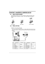
... (+) Power LED (+) Power LED (-) Power button Ground Function N/A N/A Power LED Power-on pins, the jumper is "close", if not, that means the jumper is "open". Motherboard Manual CHAPTER 3: HEADERS & JUMPERS SETUP 3.1 HOW TO SETUP JUMPERS The illustration shows how to connect the PC case's front panel switch functions. Pin opened Pin closed...
... (+) Power LED (+) Power LED (-) Power button Ground Function N/A N/A Power LED Power-on pins, the jumper is "close", if not, that means the jumper is "open". Motherboard Manual CHAPTER 3: HEADERS & JUMPERS SETUP 3.1 HOW TO SETUP JUMPERS The illustration shows how to connect the PC case's front panel switch functions. Pin opened Pin closed...

Setup Manual
Page 20
... 3 Ground 4 Right Channel Input SPDIF1: Digital Audio-out Connector This connector allows user to connect the front audio output cable with the PC front panel. Motherboard Manual F_AUDIO1: Front Panel Audio Header This header allows user to connect the PCI bracket SPDIF output header. 13 Pin Assignment 1 +5V 2 SPDIF_OUT 3 Ground 18 This...
... 3 Ground 4 Right Channel Input SPDIF1: Digital Audio-out Connector This connector allows user to connect the front audio output cable with the PC front panel. Motherboard Manual F_AUDIO1: Front Panel Audio Header This header allows user to connect the PCI bracket SPDIF output header. 13 Pin Assignment 1 +5V 2 SPDIF_OUT 3 Ground 18 This...

Setup Manual
Page 22
JUSBV2: +5V for USB ports at USB1/ RJ45USB1. Pin 2-3 Close: JUSBV1: +5V STB for USB ports at front panel (F_USB1~F_USB3). JUSBV2: +5V STB for USB ports at USB1/RJ45USB1. JUSBV1 1 3 13 JUSBV2 1 3 Pin 1-2 close 1 3 Pin 2-3 close 20 Motherboard Manual JUSBV1/JUSBV2: Power Source Headers for USB Ports Pin 1-2 Close: JUSBV1: +5V for USB ports at front panel (F_USB1~F_USB3).
JUSBV2: +5V for USB ports at USB1/ RJ45USB1. Pin 2-3 Close: JUSBV1: +5V STB for USB ports at front panel (F_USB1~F_USB3). JUSBV2: +5V STB for USB ports at USB1/RJ45USB1. JUSBV1 1 3 13 JUSBV2 1 3 Pin 1-2 close 1 3 Pin 2-3 close 20 Motherboard Manual JUSBV1/JUSBV2: Power Source Headers for USB Ports Pin 1-2 Close: JUSBV1: +5V for USB ports at front panel (F_USB1~F_USB3).
Setup Manual
Page 24
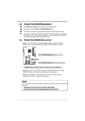
... mode. 4.4 HYBRID CROSSFIREX INSTALLATION Step 1: Insert the Hybrid CrossFireX-Ready graphics card into PEX16_1 (Master), and insert the DCCFX-P2 Paddle Card into slots completely. Motherboard Manual 4.3 HYBRID CROSSFIREX REQUIREMENTS Only Windows Vista supports Hybrid CrossFireX function. The graphics card driver should support Hybrid CrossFireX technology. Step 2: Connect a 4-pin ATX power cable...
... mode. 4.4 HYBRID CROSSFIREX INSTALLATION Step 1: Insert the Hybrid CrossFireX-Ready graphics card into PEX16_1 (Master), and insert the DCCFX-P2 Paddle Card into slots completely. Motherboard Manual 4.3 HYBRID CROSSFIREX REQUIREMENTS Only Windows Vista supports Hybrid CrossFireX function. The graphics card driver should support Hybrid CrossFireX technology. Step 2: Connect a 4-pin ATX power cable...

Setup Manual
Page 26
Motherboard Manual CHAPTER 5: RAID FUNCTIONS 5.1 OPERATING SYSTEM Supports Windows XP and Windows VISTA. 5.2 RAID ARRAYS RAID supports the following types of disk capacity. 5.3 HOW RAID WORKS RAID 0: ...
Motherboard Manual CHAPTER 5: RAID FUNCTIONS 5.1 OPERATING SYSTEM Supports Windows XP and Windows VISTA. 5.2 RAID ARRAYS RAID supports the following types of disk capacity. 5.3 HOW RAID WORKS RAID 0: ...

Setup Manual
Page 28
... RAID level 1. Fault Tolerance: Yes. Block 1 Block 3 Block 5 Block 1 Block 3 Block 5 Block 2 Block 4 Block 6 Block 2 Block 4 Block 6 26 May be stripped using RAID 0 techniques. Motherboard Manual RAID 1+0: RAID 1 drives can be simultaneously used with other RAID levels in a RAID 1+0 solution for automatic redundancy.
... RAID level 1. Fault Tolerance: Yes. Block 1 Block 3 Block 5 Block 1 Block 3 Block 5 Block 2 Block 4 Block 6 Block 2 Block 4 Block 6 26 May be stripped using RAID 0 techniques. Motherboard Manual RAID 1+0: RAID 1 drives can be simultaneously used with other RAID levels in a RAID 1+0 solution for automatic redundancy.
Setup Manual
Page 30
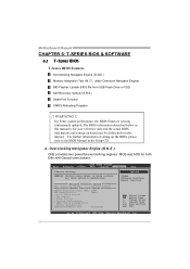
Motherboard Manual CHAPTER 6: T-SERIES BIOS & SOFTWARE 6.1 T-SERIES BIOS T-Series BIOS Features Overclocking Navigator Engine (O.N.E.) Memory Integration Test (M.I.T., under Overclock Navigator Engine) BIO-Flasher: Update BIOS file from this manual is being continuously updated. For better system ...values in below in the Setup CD. OverClock Navigator [Normal] =========== Automate OverClock System =========== Auto OverClock System [V6-Tech Engine] Manual OverClock System CPU/HT Reference Clock (MHz) [200] CPU Configuration [Auto] > G.P.U Phase Control > CPU Tuning > Clock ...
Motherboard Manual CHAPTER 6: T-SERIES BIOS & SOFTWARE 6.1 T-SERIES BIOS T-Series BIOS Features Overclocking Navigator Engine (O.N.E.) Memory Integration Test (M.I.T., under Overclock Navigator Engine) BIO-Flasher: Update BIOS file from this manual is being continuously updated. For better system ...values in below in the Setup CD. OverClock Navigator [Normal] =========== Automate OverClock System =========== Auto OverClock System [V6-Tech Engine] Manual OverClock System CPU/HT Reference Clock (MHz) [200] CPU Configuration [Auto] > G.P.U Phase Control > CPU Tuning > Clock ...

Setup Manual
Page 32
...Chipset T-Series Exit T-Series Settings WARNING: Setting wrong values in below sections may be caused by overclocking. Motherboard Manual CPU Tuning Enter this function for more clock settings. We also will not be responsible for any overclocking...may cause system to malfunction. OverClock Navigator [Normal] =========== Automate OverClock System =========== Auto ===== CPU/H CPU C > G.P OverClock Syst ======= Manual T Reference Cl onfiguration .U Phase Contr ooeOclmvker(CMlHozc)NMAkaou[[[nrtS2VAumoy06uaams0-tlOlat]Toptee]OtemcviheoO=rnv=ECse=nlr=goC=icl=nko=ec=]k=== = > CPU Tuning...
...Chipset T-Series Exit T-Series Settings WARNING: Setting wrong values in below sections may be caused by overclocking. Motherboard Manual CPU Tuning Enter this function for more clock settings. We also will not be responsible for any overclocking...may cause system to malfunction. OverClock Navigator [Normal] =========== Automate OverClock System =========== Auto ===== CPU/H CPU C > G.P OverClock Syst ======= Manual T Reference Cl onfiguration .U Phase Contr ooeOclmvker(CMlHozc)NMAkaou[[[nrtS2VAumoy06uaams0-tlOlat]Toptee]OtemcviheoO=rnv=ECse=nlr=goC=icl=nko=ec=]k=== = > CPU Tuning...
Setup Manual
Page 34
...values in below sections may cause system to malfunction. OverClock Navigator [Normal] =========== Automate OverClock System =========== Auto OverClock System [V6-Tech Engine] Manual OverClock System CPU/HT Reference Clock (MHz) [200] CPU Configuration [Auto] > G.P.U Phase Control > CPU Tuning > Clock Control > Voltage...Option F1 General Help F10 Save and Exit ESC Exit vxx.xx (C)Copyright 1985-200x, American Megatrends, Inc. B. Motherboard Manual Notices: Not all types of AMD CPU perform above overclock setting ideally; the condition parameter should be based on ...
...values in below sections may cause system to malfunction. OverClock Navigator [Normal] =========== Automate OverClock System =========== Auto OverClock System [V6-Tech Engine] Manual OverClock System CPU/HT Reference Clock (MHz) [200] CPU Configuration [Auto] > G.P.U Phase Control > CPU Tuning > Clock Control > Voltage...Option F1 General Help F10 Save and Exit ESC Exit vxx.xx (C)Copyright 1985-200x, American Megatrends, Inc. B. Motherboard Manual Notices: Not all types of AMD CPU perform above overclock setting ideally; the condition parameter should be based on ...
Setup Manual
Page 36
... Megatrends, Inc. 34 When the system hangs up due to control CPU/System Temperature vs. Fan speed. This function will automatically log in "Advanced Menu". Motherboard Manual D. E.
... Megatrends, Inc. 34 When the system hangs up due to control CPU/System Temperature vs. Fan speed. This function will automatically log in "Advanced Menu". Motherboard Manual D. E.
Setup Manual
Page 38
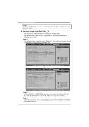
Motherboard Manual 6.2 T-SERIES SOFTWARE Installing T-Series Software 1. Insert the Setup CD to launch T-Series utility. In this panel you will see current CPU Speed and CPU/Memory/...
Motherboard Manual 6.2 T-SERIES SOFTWARE Installing T-Series Software 1. Insert the Setup CD to launch T-Series utility. In this panel you will see current CPU Speed and CPU/Memory/...

Setup Manual
Page 40
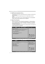
... will execute a series of testing until system fail. We strongly recommend you test every speed you can also manually adjust CPU clock by using Watchdog function. Motherboard Manual Then the utility will be saved into system registry. For beginners in over-clock field, this button and the... utility will do a fail-safe rebooting. After manually adjust the CPU clock, you should click TEST button and the utility will ...
... will execute a series of testing until system fail. We strongly recommend you test every speed you can also manually adjust CPU clock by using Watchdog function. Motherboard Manual Then the utility will be saved into system registry. For beginners in over-clock field, this button and the... utility will do a fail-safe rebooting. After manually adjust the CPU clock, you should click TEST button and the utility will ...
Setup Manual
Page 42
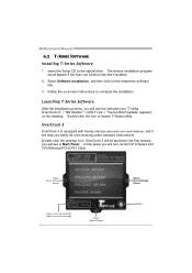
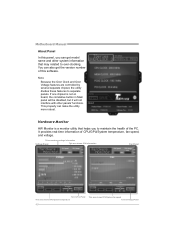
... ormation Fan Panel Turn to Fan Panel This area shows CPU/System t emperat ure This area shows CPU/System f an speed Turn to separate panels. Motherboard Manual About Panel In this software. This property can also get model name and other panels' functions. Hardware Monitor HW Monitor is not on board, the...
... ormation Fan Panel Turn to Fan Panel This area shows CPU/System t emperat ure This area shows CPU/System f an speed Turn to separate panels. Motherboard Manual About Panel In this software. This property can also get model name and other panels' functions. Hardware Monitor HW Monitor is not on board, the...


