Setup Manual
Page 2
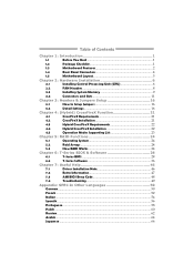
Table of Contents Chapter 1: Introduction 1 1.1 Before You Start 1 1.2 Package Checklist 1 1.3 Motherboard Features 2 1.4 Rear Panel Connectors 4 1.5 Motherboard Layout 5 Chapter 2: Hardware Installation 6 2.1 Installing Central Processing Unit (CPU 6 2.2 FAN Headers 8 2.3 Installing System Memory 9 2.4 Connectors and Slots 11 Chapter 3: Headers & Jumpers Setup 16 3.1 How to ...
Table of Contents Chapter 1: Introduction 1 1.1 Before You Start 1 1.2 Package Checklist 1 1.3 Motherboard Features 2 1.4 Rear Panel Connectors 4 1.5 Motherboard Layout 5 Chapter 2: Hardware Installation 6 2.1 Installing Central Processing Unit (CPU 6 2.2 FAN Headers 8 2.3 Installing System Memory 9 2.4 Connectors and Slots 11 Chapter 3: Headers & Jumpers Setup 16 3.1 How to ...
Setup Manual
Page 3
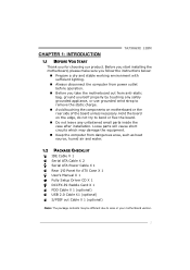
... the rear side of the board unless necessary. Before you start installing the motherboard, please make sure you follow the instructions below: „ Prepare a dry and stable working environment with sufficient lighting. „ Always disconnect ... computer from anti-static bag, ground yourself properly by touching any unfastened small parts inside the case after installation. CHAPTER 1: INTRODUCTION TA790GXE 128M 1.1 BEFORE YOU START Thank you take the motherboard out from dangerous area, such as heat source, humid air and water. 1.2 PACKAGE CHECKLIST IDE Cable X 1 Serial ATA Cable ...
... the rear side of the board unless necessary. Before you start installing the motherboard, please make sure you follow the instructions below: „ Prepare a dry and stable working environment with sufficient lighting. „ Always disconnect ... computer from anti-static bag, ground yourself properly by touching any unfastened small parts inside the case after installation. CHAPTER 1: INTRODUCTION TA790GXE 128M 1.1 BEFORE YOU START Thank you take the motherboard out from dangerous area, such as heat source, humid air and water. 1.2 PACKAGE CHECKLIST IDE Cable X 1 Serial ATA Cable ...
Setup Manual
Page 4
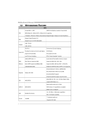
Motherboard Manual 1.3 MOTHERBOARD FEATURES SPEC Socket AM2+ / AM3 AMD 64 Architecture enables 32 and 64 bit CPU AMD Athlon 64 / Athlon 64 FX / Athlon 64 x2 computing / Sempron / ...
Motherboard Manual 1.3 MOTHERBOARD FEATURES SPEC Socket AM2+ / AM3 AMD 64 Architecture enables 32 and 64 bit CPU AMD Athlon 64 / Athlon 64 FX / Athlon 64 x2 computing / Sempron / ...

Setup Manual
Page 6
... different display panels simultaneously. 4 The chipset uses the same channel to control HDMI and DVI-D, so these two interfaces cannot work at the same time. Motherboard Manual 1.4 REAR PANEL CONNECTORS X PS/2 Mouse Port Y PS/2 Keyboard Port Z HDMI Port The High-Definition Multimedia Interface (HDMI) is a video interface transmitting digital video signals...
... different display panels simultaneously. 4 The chipset uses the same channel to control HDMI and DVI-D, so these two interfaces cannot work at the same time. Motherboard Manual 1.4 REAR PANEL CONNECTORS X PS/2 Mouse Port Y PS/2 Keyboard Port Z HDMI Port The High-Definition Multimedia Interface (HDMI) is a video interface transmitting digital video signals...
Setup Manual
Page 7
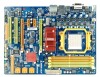
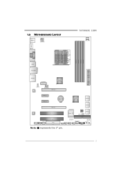
1.5 MOTHERBOARD LAYOUT KBMS 1 ATXPWR1 TA790GXE 128M CPU_ FAN1 HDMI1 S ocket A M 2+ DVI VG A PH1 PH2 PH3 PH4 DIMM A1 DIMM B1 DIMM A2 DIMM B2 USB1 RJ4 5USB1 ATXPWR2 AUDIO2 AUXPWR1 AMD 790GX JUSBV1 L AN SYS_FAN1 PEX16_ 2 PEX1 _1 PEX1 _2 BAT1 AMD SB750 SATA5-6 PEX16_ 1 SATA3-4 Co de c PCI1 Super I/O BI O S JCMOS1 SATA1-2 S PDIF1 F_AUDIO1 CD_IN1 PCI2 FDD1 IDE1 SYS_FA N2 LED_D1 LED_D2 SW_ RST JUSBV 2 F_USB 3 F_USB2 F_USB 1 PANEL1 SW_P WR Note: ■ represents the 1st pin. 5
1.5 MOTHERBOARD LAYOUT KBMS 1 ATXPWR1 TA790GXE 128M CPU_ FAN1 HDMI1 S ocket A M 2+ DVI VG A PH1 PH2 PH3 PH4 DIMM A1 DIMM B1 DIMM A2 DIMM B2 USB1 RJ4 5USB1 ATXPWR2 AUDIO2 AUXPWR1 AMD 790GX JUSBV1 L AN SYS_FAN1 PEX16_ 2 PEX1 _1 PEX1 _2 BAT1 AMD SB750 SATA5-6 PEX16_ 1 SATA3-4 Co de c PCI1 Super I/O BI O S JCMOS1 SATA1-2 S PDIF1 F_AUDIO1 CD_IN1 PCI2 FDD1 IDE1 SYS_FA N2 LED_D1 LED_D2 SW_ RST JUSBV 2 F_USB 3 F_USB2 F_USB 1 PANEL1 SW_P WR Note: ■ represents the 1st pin. 5

Setup Manual
Page 8
Step 2: Pull the lever toward direction A from the socket and then raise the lever up to a 90-degree angle. Motherboard Manual CHAPTER 2: HARDWARE INSTALLATION 2.1 INSTALLING CENTRAL PROCESSING UNIT (CPU) Step 1: Remove the socket protection cap. The CPU will fit only in the correct orientation. 6 Step 3: Look for the white triangle on socket, and the gold triangle on CPU should point towards this white triangle.
Step 2: Pull the lever toward direction A from the socket and then raise the lever up to a 90-degree angle. Motherboard Manual CHAPTER 2: HARDWARE INSTALLATION 2.1 INSTALLING CENTRAL PROCESSING UNIT (CPU) Step 1: Remove the socket protection cap. The CPU will fit only in the correct orientation. 6 Step 3: Look for the white triangle on socket, and the gold triangle on CPU should point towards this white triangle.

Setup Manual
Page 10
Motherboard Manual 2.2 FAN HEADERS These fan headers support cooling-fans built in the computer. CPU_FAN1: CPU Fan Header 1 4 Pin Assignment 1 Ground 2 +12V 3 FAN RPM rate sense 4 ...
Motherboard Manual 2.2 FAN HEADERS These fan headers support cooling-fans built in the computer. CPU_FAN1: CPU Fan Header 1 4 Pin Assignment 1 Ground 2 +12V 3 FAN RPM rate sense 4 ...

Setup Manual
Page 12
... refer to the following requirements to activate Dual Channel function: Install memory module of the memory module must be the same (x8 or x16) 10 Motherboard Manual B.
... refer to the following requirements to activate Dual Channel function: Install memory module of the memory module must be the same (x8 or x16) 10 Motherboard Manual B.
Setup Manual
Page 13
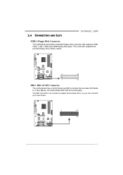
2.4 CONNECTORS AND SLOTS TA790GXE 128M FDD1: Floppy Disk Connector The motherboard provides a standard floppy disk connector that provides PIO Mode 0~4, Bus Master, and Ultra DMA 33/66/100/133 functionality. This connector supports the provided floppy drive ribbon cables. 2 34 1 33 IDE1: IDE/ATAPI Connector The motherboard has a 32-bit Enhanced IDE Controller that supports 360K, 720K, 1.2M, 1.44M and 2.88M floppy disk types. The IDE connector can connect a master and a slave drive, so you can connect up to two drives. 2 40 1 39 11
2.4 CONNECTORS AND SLOTS TA790GXE 128M FDD1: Floppy Disk Connector The motherboard provides a standard floppy disk connector that provides PIO Mode 0~4, Bus Master, and Ultra DMA 33/66/100/133 functionality. This connector supports the provided floppy drive ribbon cables. 2 34 1 33 IDE1: IDE/ATAPI Connector The motherboard has a 32-bit Enhanced IDE Controller that supports 360K, 720K, 1.2M, 1.44M and 2.88M floppy disk types. The IDE connector can connect a master and a slave drive, so you can connect up to two drives. 2 40 1 39 11

Setup Manual
Page 14
Pin Assignment 1 4 1 +12V 2 Ground 3 Ground 4 VCC 12 Motherboard Manual SATA1-2/SATA3-4/SATA5-6: Serial ATA Connectors The motherboard has a PCI to SATA Controller with 6 channels SATA interface, it satisfies the SATA 2.0 spec and with transfer rate of 3.0Gb/s. Exclusive power for graphics cards. SATA1 -2 SATA3-4 SATA5 -6 AUXPWR1: Auxiliary Power for Graphics This connector is an auxiliary power connection for the graphics card provides better graphics performance.
Pin Assignment 1 4 1 +12V 2 Ground 3 Ground 4 VCC 12 Motherboard Manual SATA1-2/SATA3-4/SATA5-6: Serial ATA Connectors The motherboard has a PCI to SATA Controller with 6 channels SATA interface, it satisfies the SATA 2.0 spec and with transfer rate of 3.0Gb/s. Exclusive power for graphics cards. SATA1 -2 SATA3-4 SATA5 -6 AUXPWR1: Auxiliary Power for Graphics This connector is an auxiliary power connection for the graphics card provides better graphics performance.

Setup Manual
Page 16
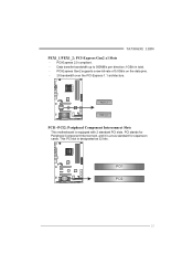
... is reserved for graphics or video cards. PCI-Express Gen2 supports a raw bit-rate of 16GB/s totally. (Must be with multiple displays. Motherboard Manual PEX16_1: PCI-Express Gen2 x16 Slot (x16/x8 Speed) - PEX16_1 slot is reserved for graphics or video cards. When using CrossFireX, this... motherboard supports dual PCI-Express graphics cards using CrossFireX technology with x16 speed, please insert the Paddle Card DCCFX-P2 into PEX16_2. PEX16_2:...
... is reserved for graphics or video cards. PCI-Express Gen2 supports a raw bit-rate of 16GB/s totally. (Must be with multiple displays. Motherboard Manual PEX16_1: PCI-Express Gen2 x16 Slot (x16/x8 Speed) - PEX16_1 slot is reserved for graphics or video cards. When using CrossFireX, this... motherboard supports dual PCI-Express graphics cards using CrossFireX technology with x16 speed, please insert the Paddle Card DCCFX-P2 into PEX16_2. PEX16_2:...
Setup Manual
Page 17
This PCI slot is a bus standard for expansion cards. PCI1 PCI2 15 PCI-Express Gen2 supports a raw bit-rate of 5.0Gb/s on the data pins. - 2X bandwidth over the PCI-Express 1.1 architecture. PCI stands for Peripheral Component Interconnect, and it is designated as 32 bits. PCI-Express 2.0 compliant. - P E X 1_ 1 P E X 1_ 2 PCI1~PCI2: Peripheral Component Interconnect Slots This motherboard is equipped with 2 standard PCI slots. Data transfer bandwidth up to 500MB/s per direction; 1GB/s in total. - TA790GXE 128M PEX1_1/PEX1_2: PCI-Express Gen2 x1 Slots -
This PCI slot is a bus standard for expansion cards. PCI1 PCI2 15 PCI-Express Gen2 supports a raw bit-rate of 5.0Gb/s on the data pins. - 2X bandwidth over the PCI-Express 1.1 architecture. PCI stands for Peripheral Component Interconnect, and it is designated as 32 bits. PCI-Express 2.0 compliant. - P E X 1_ 1 P E X 1_ 2 PCI1~PCI2: Peripheral Component Interconnect Slots This motherboard is equipped with 2 standard PCI slots. Data transfer bandwidth up to 500MB/s per direction; 1GB/s in total. - TA790GXE 128M PEX1_1/PEX1_2: PCI-Express Gen2 x1 Slots -
Setup Manual
Page 18
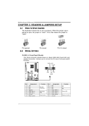
... LED, and speaker connection. Pin opened Pin closed 3.2 DETAIL SETTINGS Pin1-2 closed PANEL1: Front Panel Header This 16-pin connector includes Power-on button 16 Motherboard Manual CHAPTER 3: HEADERS & JUMPERS SETUP 3.1 HOW TO SETUP JUMPERS The illustration shows how to connect the PC case's front panel switch functions. It allows user...
... LED, and speaker connection. Pin opened Pin closed 3.2 DETAIL SETTINGS Pin1-2 closed PANEL1: Front Panel Header This 16-pin connector includes Power-on button 16 Motherboard Manual CHAPTER 3: HEADERS & JUMPERS SETUP 3.1 HOW TO SETUP JUMPERS The illustration shows how to connect the PC case's front panel switch functions. It allows user...
Setup Manual
Page 19
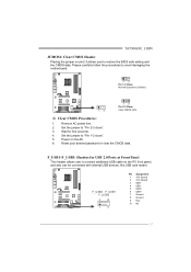
Wait for USB 2.0 Ports at Front Panel This header allows user to avoid damaging the motherboard. 13 Pin 1-2 Close: Normal Operation (Default). 1 3 13 Pin 2-3 Close: Clear CMOS data. ※ Clear CMOS Procedures: 1. F_USB1~F_USB3: Headers for five seconds. 4. Reset your desired ... with internal USB devices, like USB card reader. Remove AC power line. 2. Set the jumper to restore the BIOS safe setting and the CMOS data. TA790GXE 128M JCMOS1: Clear CMOS Header Placing the jumper on pin2-3 allows user to "Pin 2-3 close ". 5. Set the jumper to "Pin 1-2 close...
Wait for USB 2.0 Ports at Front Panel This header allows user to avoid damaging the motherboard. 13 Pin 1-2 Close: Normal Operation (Default). 1 3 13 Pin 2-3 Close: Clear CMOS data. ※ Clear CMOS Procedures: 1. F_USB1~F_USB3: Headers for five seconds. 4. Reset your desired ... with internal USB devices, like USB card reader. Remove AC power line. 2. Set the jumper to restore the BIOS safe setting and the CMOS data. TA790GXE 128M JCMOS1: Clear CMOS Header Placing the jumper on pin2-3 allows user to "Pin 2-3 close ". 5. Set the jumper to "Pin 1-2 close...

Setup Manual
Page 20
... 3 Ground 4 Right Channel Input SPDIF1: Digital Audio-out Connector This connector allows user to connect the front audio output cable with the PC front panel. Motherboard Manual F_AUDIO1: Front Panel Audio Header This header allows user to connect the PCI bracket SPDIF output header. 13 Pin Assignment 1 +5V 2 SPDIF_OUT 3 Ground 18...
... 3 Ground 4 Right Channel Input SPDIF1: Digital Audio-out Connector This connector allows user to connect the front audio output cable with the PC front panel. Motherboard Manual F_AUDIO1: Front Panel Audio Header This header allows user to connect the PCI bracket SPDIF output header. 13 Pin Assignment 1 +5V 2 SPDIF_OUT 3 Ground 18...

Setup Manual
Page 22
JUSBV1 1 3 13 JUSBV2 1 3 Pin 1-2 close 1 3 Pin 2-3 close 20 JUSBV2: +5V STB for USB ports at USB1/RJ45USB1. Motherboard Manual JUSBV1/JUSBV2: Power Source Headers for USB Ports Pin 1-2 Close: JUSBV1: +5V for USB ports at front panel (F_USB1~F_USB3). JUSBV2: +5V for USB ports at front panel (F_USB1~F_USB3). Pin 2-3 Close: JUSBV1: +5V STB for USB ports at USB1/ RJ45USB1.
JUSBV1 1 3 13 JUSBV2 1 3 Pin 1-2 close 1 3 Pin 2-3 close 20 JUSBV2: +5V STB for USB ports at USB1/RJ45USB1. Motherboard Manual JUSBV1/JUSBV2: Power Source Headers for USB Ports Pin 1-2 Close: JUSBV1: +5V for USB ports at front panel (F_USB1~F_USB3). JUSBV2: +5V for USB ports at front panel (F_USB1~F_USB3). Pin 2-3 Close: JUSBV1: +5V STB for USB ports at USB1/ RJ45USB1.
Setup Manual
Page 24
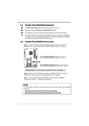
...-P2 Pad d le C ard PEX16 _1(Master) Rad eon HD3450 Rad eon HD3470 Notice: Make sure both cards are seated into PEX16_2 (Slave). Installation completes. Motherboard Manual 4.3 HYBRID CROSSFIREX REQUIREMENTS Only Windows Vista supports Hybrid CrossFireX function. The power supply unit must provide at least the minimum power required by the...
...-P2 Pad d le C ard PEX16 _1(Master) Rad eon HD3450 Rad eon HD3470 Notice: Make sure both cards are seated into PEX16_2 (Slave). Installation completes. Motherboard Manual 4.3 HYBRID CROSSFIREX REQUIREMENTS Only Windows Vista supports Hybrid CrossFireX function. The power supply unit must provide at least the minimum power required by the...

Setup Manual
Page 26
Motherboard Manual CHAPTER 5: RAID FUNCTIONS 5.1 OPERATING SYSTEM Supports Windows XP and Windows VISTA. 5.2 RAID ARRAYS RAID supports the following types of the RAID set during the ...
Motherboard Manual CHAPTER 5: RAID FUNCTIONS 5.1 OPERATING SYSTEM Supports Windows XP and Windows VISTA. 5.2 RAID ARRAYS RAID supports the following types of the RAID set during the ...

Setup Manual
Page 28
... improved resiliency, performance and rebuild performance. May be stripped using RAID 0 techniques. Block 1 Block 3 Block 5 Block 1 Block 3 Block 5 Block 2 Block 4 Block 6 Block 2 Block 4 Block 6 26 Motherboard Manual RAID 1+0: RAID 1 drives can be simultaneously used with other RAID levels in a RAID 1+0 solution for automatic redundancy.
... improved resiliency, performance and rebuild performance. May be stripped using RAID 0 techniques. Block 1 Block 3 Block 5 Block 1 Block 3 Block 5 Block 2 Block 4 Block 6 Block 2 Block 4 Block 6 26 Motherboard Manual RAID 1+0: RAID 1 drives can be simultaneously used with other RAID levels in a RAID 1+0 solution for automatic redundancy.
Setup Manual
Page 30
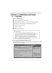
... CD. The BIOS information described below sections may be different from USB Flash Drive or FDD Self Recovery System (S.R.S) Smart Fan Function CMOS Reloading Program !! Motherboard Manual CHAPTER 6: T-SERIES BIOS & SOFTWARE 6.1 T-SERIES BIOS T-Series BIOS Features Overclocking Navigator Engine (O.N.E.) Memory Integration Test (M.I.T., under Overclock Navigator Engine) BIO-Flasher: Update BIOS file...
... CD. The BIOS information described below sections may be different from USB Flash Drive or FDD Self Recovery System (S.R.S) Smart Fan Function CMOS Reloading Program !! Motherboard Manual CHAPTER 6: T-SERIES BIOS & SOFTWARE 6.1 T-SERIES BIOS T-Series BIOS Features Overclocking Navigator Engine (O.N.E.) Memory Integration Test (M.I.T., under Overclock Navigator Engine) BIO-Flasher: Update BIOS file...

