Setup Manual
Page 1
...and used in accordance with the instructions, may cause harmful interference to provide reasonable protection against harmful interference in this user's manual is subject to notify any party beforehand. There is not allowed without notice and we will not occur in writing. All ...particular installation. Duplication of this publication and to make changes to the contents here without obligation to be responsible for any purpose. TA790GXE 128MSetup Manual FCC Information and Copyright This equipment has been tested and found to comply with the limits of a Class B digital device, ...
...and used in accordance with the instructions, may cause harmful interference to provide reasonable protection against harmful interference in this user's manual is subject to notify any party beforehand. There is not allowed without notice and we will not occur in writing. All ...particular installation. Duplication of this publication and to make changes to the contents here without obligation to be responsible for any purpose. TA790GXE 128MSetup Manual FCC Information and Copyright This equipment has been tested and found to comply with the limits of a Class B digital device, ...
Setup Manual
Page 3
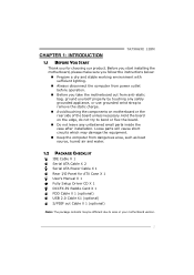
... dry and stable working environment with sufficient lighting. „ Always disconnect the computer from power outlet before operation. „ Before you for ATX Case X 1 User's Manual X 1 Fully Setup Driver CD X 1 DCCFX-P2 Paddle Card X 1 FDD Cable X 1 (optional) USB 2.0 Cable X1 (optional) S/PDIF out Cable X 1...or your motherboard version. 1 Hold the board on motherboard or the rear side of the board unless necessary. CHAPTER 1: INTRODUCTION TA790GXE 128M 1.1 BEFORE YOU START Thank you take the motherboard out from anti-static bag, ground yourself properly by touching any unfastened ...
... dry and stable working environment with sufficient lighting. „ Always disconnect the computer from power outlet before operation. „ Before you for ATX Case X 1 User's Manual X 1 Fully Setup Driver CD X 1 DCCFX-P2 Paddle Card X 1 FDD Cable X 1 (optional) USB 2.0 Cable X1 (optional) S/PDIF out Cable X 1...or your motherboard version. 1 Hold the board on motherboard or the rear side of the board unless necessary. CHAPTER 1: INTRODUCTION TA790GXE 128M 1.1 BEFORE YOU START Thank you take the motherboard out from anti-static bag, ground yourself properly by touching any unfastened ...
Setup Manual
Page 4
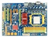
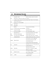
Motherboard Manual 1.3 MOTHERBOARD FEATURES SPEC Socket AM2+ / AM3 AMD 64 Architecture enables 32 and 64 bit CPU AMD Athlon 64 / Athlon 64 FX / Athlon 64 x2 computing / ...
Motherboard Manual 1.3 MOTHERBOARD FEATURES SPEC Socket AM2+ / AM3 AMD 64 Architecture enables 32 and 64 bit CPU AMD Athlon 64 / Athlon 64 FX / Athlon 64 x2 computing / ...

Setup Manual
Page 6
... Transmit analog video signals to computer monitor or any compatible digital audio and/or video monitor, such as flat panel LCDs or digital projectors. Motherboard Manual 1.4 REAR PANEL CONNECTORS X PS/2 Mouse Port Y PS/2 Keyboard Port Z HDMI Port The High-Definition Multimedia Interface (HDMI) is a video interface transmitting digital video signals to...
... Transmit analog video signals to computer monitor or any compatible digital audio and/or video monitor, such as flat panel LCDs or digital projectors. Motherboard Manual 1.4 REAR PANEL CONNECTORS X PS/2 Mouse Port Y PS/2 Keyboard Port Z HDMI Port The High-Definition Multimedia Interface (HDMI) is a video interface transmitting digital video signals to...

Setup Manual
Page 8
Motherboard Manual CHAPTER 2: HARDWARE INSTALLATION 2.1 INSTALLING CENTRAL PROCESSING UNIT (CPU) Step 1: Remove the socket protection cap. Step 2: Pull the lever toward direction A from the socket and then raise the lever up to a 90-degree angle. Step 3: Look for the white triangle on socket, and the gold triangle on CPU should point towards this white triangle. The CPU will fit only in the correct orientation. 6
Motherboard Manual CHAPTER 2: HARDWARE INSTALLATION 2.1 INSTALLING CENTRAL PROCESSING UNIT (CPU) Step 1: Remove the socket protection cap. Step 2: Pull the lever toward direction A from the socket and then raise the lever up to a 90-degree angle. Step 3: Look for the white triangle on socket, and the gold triangle on CPU should point towards this white triangle. The CPU will fit only in the correct orientation. 6

Setup Manual
Page 10
... red wire is the positive and should be connected to pin#2, and the black wire is Ground and should be different according to pin#1. Motherboard Manual 2.2 FAN HEADERS These fan headers support cooling-fans built in the computer.
... red wire is the positive and should be connected to pin#2, and the black wire is Ground and should be different according to pin#1. Motherboard Manual 2.2 FAN HEADERS These fan headers support cooling-fans built in the computer.

Setup Manual
Page 12
... to the following requirements to activate Dual Channel function: Install memory module of the memory module must be the same (x8 or x16) 10 C. Motherboard Manual B. Memory Capacity DIMM Socket Location DIMMA1 DIMMB1 DIMMA2 DIMMB2 DDR2 Module 256MB/512MB/1GB/2GB/4GB 256MB/512MB/1GB/2GB/4GB 256MB/512MB/1GB/2GB...
... to the following requirements to activate Dual Channel function: Install memory module of the memory module must be the same (x8 or x16) 10 C. Motherboard Manual B. Memory Capacity DIMM Socket Location DIMMA1 DIMMB1 DIMMA2 DIMMB2 DDR2 Module 256MB/512MB/1GB/2GB/4GB 256MB/512MB/1GB/2GB/4GB 256MB/512MB/1GB/2GB...

Setup Manual
Page 14
Motherboard Manual SATA1-2/SATA3-4/SATA5-6: Serial ATA Connectors The motherboard has a PCI to SATA Controller with 6 channels SATA interface, it satisfies the SATA 2.0 spec and with transfer rate of 3.0Gb/s. Pin Assignment 1 4 1 +12V 2 Ground 3 Ground 4 VCC 12 Exclusive power for graphics cards. SATA1 -2 SATA3-4 SATA5 -6 AUXPWR1: Auxiliary Power for Graphics This connector is an auxiliary power connection for the graphics card provides better graphics performance.
Motherboard Manual SATA1-2/SATA3-4/SATA5-6: Serial ATA Connectors The motherboard has a PCI to SATA Controller with 6 channels SATA interface, it satisfies the SATA 2.0 spec and with transfer rate of 3.0Gb/s. Pin Assignment 1 4 1 +12V 2 Ground 3 Ground 4 VCC 12 Exclusive power for graphics cards. SATA1 -2 SATA3-4 SATA5 -6 AUXPWR1: Auxiliary Power for Graphics This connector is an auxiliary power connection for the graphics card provides better graphics performance.

Setup Manual
Page 16
.... - x8 Speed Mode: Maximum theoretical realized bandwidth of 8GB/s totally. - When using CrossFireX. - Note: NVIDIA Dual Graphics is reserved for graphics or video cards. Motherboard Manual PEX16_1: PCI-Express Gen2 x16 Slot (x16/x8 Speed) - PCI-Express Gen2 supports a raw bit-rate of 5.0Gb/s on the data pins. - 2X bandwidth over...
.... - x8 Speed Mode: Maximum theoretical realized bandwidth of 8GB/s totally. - When using CrossFireX. - Note: NVIDIA Dual Graphics is reserved for graphics or video cards. Motherboard Manual PEX16_1: PCI-Express Gen2 x16 Slot (x16/x8 Speed) - PCI-Express Gen2 supports a raw bit-rate of 5.0Gb/s on the data pins. - 2X bandwidth over...
Setup Manual
Page 18
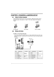
... 16 Assignment N/A N/A N/A Power LED (+) Power LED (+) Power LED (-) Power button Ground Function N/A N/A Power LED Power-on , Reset, HDD LED, Power LED, and speaker connection. Motherboard Manual CHAPTER 3: HEADERS & JUMPERS SETUP 3.1 HOW TO SETUP JUMPERS The illustration shows how to connect the PC case's front panel switch functions. When the jumper cap...
... 16 Assignment N/A N/A N/A Power LED (+) Power LED (+) Power LED (-) Power button Ground Function N/A N/A Power LED Power-on , Reset, HDD LED, Power LED, and speaker connection. Motherboard Manual CHAPTER 3: HEADERS & JUMPERS SETUP 3.1 HOW TO SETUP JUMPERS The illustration shows how to connect the PC case's front panel switch functions. When the jumper cap...

Setup Manual
Page 20
... 4 Right Channel Input SPDIF1: Digital Audio-out Connector This connector allows user to connect the front audio output cable with the PC front panel. Motherboard Manual F_AUDIO1: Front Panel Audio Header This header allows user to connect the PCI bracket SPDIF output header. 13 Pin Assignment 1 +5V 2 SPDIF_OUT 3 Ground 18...
... 4 Right Channel Input SPDIF1: Digital Audio-out Connector This connector allows user to connect the front audio output cable with the PC front panel. Motherboard Manual F_AUDIO1: Front Panel Audio Header This header allows user to connect the PCI bracket SPDIF output header. 13 Pin Assignment 1 +5V 2 SPDIF_OUT 3 Ground 18...

Setup Manual
Page 22
Pin 2-3 Close: JUSBV1: +5V STB for USB ports at front panel (F_USB1~F_USB3). JUSBV2: +5V for USB ports at USB1/ RJ45USB1. Motherboard Manual JUSBV1/JUSBV2: Power Source Headers for USB Ports Pin 1-2 Close: JUSBV1: +5V for USB ports at front panel (F_USB1~F_USB3). JUSBV2: +5V STB for USB ports at USB1/RJ45USB1. JUSBV1 1 3 13 JUSBV2 1 3 Pin 1-2 close 1 3 Pin 2-3 close 20
Pin 2-3 Close: JUSBV1: +5V STB for USB ports at front panel (F_USB1~F_USB3). JUSBV2: +5V for USB ports at USB1/ RJ45USB1. Motherboard Manual JUSBV1/JUSBV2: Power Source Headers for USB Ports Pin 1-2 Close: JUSBV1: +5V for USB ports at front panel (F_USB1~F_USB3). JUSBV2: +5V STB for USB ports at USB1/RJ45USB1. JUSBV1 1 3 13 JUSBV2 1 3 Pin 1-2 close 1 3 Pin 2-3 close 20
Setup Manual
Page 24
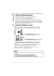
... slots completely. A graphics card with Radeon HD3450/HD3470 GPU. Step 2: Connect a 4-pin ATX power cable to Auxiliary Power Connector (AUXPWR1), this will be unstable. Motherboard Manual 4.3 HYBRID CROSSFIREX REQUIREMENTS Only Windows Vista supports Hybrid CrossFireX function. The power supply unit must provide at least the minimum power required by the system...
... slots completely. A graphics card with Radeon HD3450/HD3470 GPU. Step 2: Connect a 4-pin ATX power cable to Auxiliary Power Connector (AUXPWR1), this will be unstable. Motherboard Manual 4.3 HYBRID CROSSFIREX REQUIREMENTS Only Windows Vista supports Hybrid CrossFireX function. The power supply unit must provide at least the minimum power required by the system...

Setup Manual
Page 26
... 1 defines techniques for parity. Drawbacks: Does not deliver any drive in a RAID 0 array system. If any fault tolerance. Depending on the system environment. Motherboard Manual CHAPTER 5: RAID FUNCTIONS 5.1 OPERATING SYSTEM Supports Windows XP and Windows VISTA. 5.2 RAID ARRAYS RAID supports the following types of RAID arrays: RAID 0: RAID 0 defines a disk...
... 1 defines techniques for parity. Drawbacks: Does not deliver any drive in a RAID 0 array system. If any fault tolerance. Depending on the system environment. Motherboard Manual CHAPTER 5: RAID FUNCTIONS 5.1 OPERATING SYSTEM Supports Windows XP and Windows VISTA. 5.2 RAID ARRAYS RAID supports the following types of RAID arrays: RAID 0: RAID 0 defines a disk...
Setup Manual
Page 27
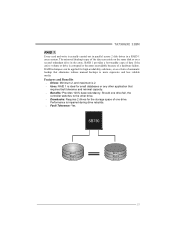
...the storage space of data if the active volume or drive is actually carried out in parallel across 2 disk drives in the array. TA790GXE 128M RAID 1: Every read and write is corrupted or becomes unavailable because of a hardware failure. RAID 1 provides a hot-standby copy ... or any other drive. Drawbacks: Requires 2 drives for high-availability solutions, or as a form of automatic backup that eliminates tedious manual backups to the other application that requires fault tolerance and minimal capacity. Benefits: Provides 100% data redundancy. Features and Benefits ...
...the storage space of data if the active volume or drive is actually carried out in parallel across 2 disk drives in the array. TA790GXE 128M RAID 1: Every read and write is corrupted or becomes unavailable because of a hardware failure. RAID 1 provides a hot-standby copy ... or any other drive. Drawbacks: Requires 2 drives for high-availability solutions, or as a form of automatic backup that eliminates tedious manual backups to the other application that requires fault tolerance and minimal capacity. Benefits: Provides 100% data redundancy. Features and Benefits ...

Setup Manual
Page 28
... Drives: Minimum 4, and maximum is 6 or 8, depending on the platform. Benefits: Optimizes for both fault tolerance and performance, allowing for automatic redundancy. Motherboard Manual RAID 1+0: RAID 1 drives can be simultaneously used with other RAID levels in a RAID 1+0 solution for improved resiliency, performance and rebuild performance.
... Drives: Minimum 4, and maximum is 6 or 8, depending on the platform. Benefits: Optimizes for both fault tolerance and performance, allowing for automatic redundancy. Motherboard Manual RAID 1+0: RAID 1 drives can be simultaneously used with other RAID levels in a RAID 1+0 solution for improved resiliency, performance and rebuild performance.
Setup Manual
Page 30
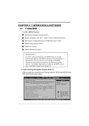
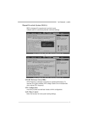
...: Setting wrong values in below in the Setup CD. OverClock Navigator [Normal] =========== Automate OverClock System =========== Auto OverClock System [V6-Tech Engine] Manual OverClock System CPU/HT Reference Clock (MHz) [200] CPU Configuration [Auto] > G.P.U Phase Control > CPU Tuning > Clock Control > Voltage Configuation...AOS for your reference only and the actual BIOS information and settings on board may cause system to the BIOS Manual in this manual. Change Option F1 General Help F10 Save and Exit ESC Exit vxx.xx (C)Copyright 1985-200x, American Megatrends...
...: Setting wrong values in below in the Setup CD. OverClock Navigator [Normal] =========== Automate OverClock System =========== Auto OverClock System [V6-Tech Engine] Manual OverClock System CPU/HT Reference Clock (MHz) [200] CPU Configuration [Auto] > G.P.U Phase Control > CPU Tuning > Clock Control > Voltage Configuation...AOS for your reference only and the actual BIOS information and settings on board may cause system to the BIOS Manual in this manual. Change Option F1 General Help F10 Save and Exit ESC Exit vxx.xx (C)Copyright 1985-200x, American Megatrends...
Setup Manual
Page 31
...Clock Control > Voltage Configuation > DRAM Timing Configuration > Memory Configuration Integrated Memory Test [Disabled] Options Normal Automate OverClock Manual OverClock Select Screen Select Item +- G.P.U Phase Control Enter this function for experienced overclock users. Change Option F1 General ...> Voltage Configuation > DRAM Timing Configuration > Memory Configuration Integrated Memory Test [Disabled] Options Normal Automate OverClock Manual OverClock Select Screen Select Item +- Main Advanced PCIPnP BIOS SETUP UTILITY Boot Chipset T-Series Exit T-Series Settings...
...Clock Control > Voltage Configuation > DRAM Timing Configuration > Memory Configuration Integrated Memory Test [Disabled] Options Normal Automate OverClock Manual OverClock Select Screen Select Item +- G.P.U Phase Control Enter this function for experienced overclock users. Change Option F1 General ...> Voltage Configuation > DRAM Timing Configuration > Memory Configuration Integrated Memory Test [Disabled] Options Normal Automate OverClock Manual OverClock Select Screen Select Item +- Main Advanced PCIPnP BIOS SETUP UTILITY Boot Chipset T-Series Exit T-Series Settings...

Setup Manual
Page 32
... clock settings. OverClock Navigator [Normal] =========== Automate OverClock System =========== Auto ===== CPU/H CPU C > G.P OverClock Syst ======= Manual T Reference Cl onfiguration .U Phase Contr ooeOclmvker(CMlHozc)NMAkaou[[[nrtS2VAumoy06uaams0-tlOlat]Toptee]OtemcviheoO=rnv=ECse=nlr=goC=icl=nko=ec=]k=== =... > Voltage Configuation > DRAM Timing Configuration > Memory Configuration Integrated Memory Test [Disabled] Options Normal Automate OverClock Manual OverClock Select Screen Select Item +- Therefore, we will not guarantee any hardware damage which may cause system to...
... clock settings. OverClock Navigator [Normal] =========== Automate OverClock System =========== Auto ===== CPU/H CPU C > G.P OverClock Syst ======= Manual T Reference Cl onfiguration .U Phase Contr ooeOclmvker(CMlHozc)NMAkaou[[[nrtS2VAumoy06uaams0-tlOlat]Toptee]OtemcviheoO=rnv=ECse=nlr=goC=icl=nko=ec=]k=== =... > Voltage Configuation > DRAM Timing Configuration > Memory Configuration Integrated Memory Test [Disabled] Options Normal Automate OverClock Manual OverClock Select Screen Select Item +- Therefore, we will not guarantee any hardware damage which may cause system to...
Setup Manual
Page 33
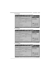
...Change Option F1 General Help F10 Save and Exit ESC Exit vxx.xx (C)Copyright 1985-200x, American Megatrends, Inc. TA790GXE 128M V6 Tech Engine This engine will make a better over-clock performance. Main Advanced PCIPnP BIOS SETUP UTILITY Boot ...(C)Copyright 1985-200x, American Megatrends, Inc. 31 OverClock Navigator [Automate OverClock] =========== Automate OverClock System =========== Auto OverClock System [V6-Tech Engine] Manual OverClock System CPU/HT Reference Clock (MHz) [200] CPU Configuration [Auto] > G.P.U Phase Control > CPU Tuning > Clock Control > Voltage...
...Change Option F1 General Help F10 Save and Exit ESC Exit vxx.xx (C)Copyright 1985-200x, American Megatrends, Inc. TA790GXE 128M V6 Tech Engine This engine will make a better over-clock performance. Main Advanced PCIPnP BIOS SETUP UTILITY Boot ...(C)Copyright 1985-200x, American Megatrends, Inc. 31 OverClock Navigator [Automate OverClock] =========== Automate OverClock System =========== Auto OverClock System [V6-Tech Engine] Manual OverClock System CPU/HT Reference Clock (MHz) [200] CPU Configuration [Auto] > G.P.U Phase Control > CPU Tuning > Clock Control > Voltage...

