Setup Manual
Page 3
CHAPTER 1: INTRODUCTION TA790GXE 128M 1.1 BEFORE YOU START Thank you take the motherboard out from dangerous area, such as heat source, humid air and water. 1.2 PACKAGE CHECKLIST IDE Cable X 1 Serial ATA Cable X 2 Serial ATA Power Cable X 1 Rear I/O Panel...charge. „ Avoid touching the components on the edge, do not try to area or your motherboard version. 1 Hold the board on motherboard or the rear side of the board unless necessary. Before you start installing the motherboard, please make sure you follow the instructions below: „ Prepare a dry and stable working ...
CHAPTER 1: INTRODUCTION TA790GXE 128M 1.1 BEFORE YOU START Thank you take the motherboard out from dangerous area, such as heat source, humid air and water. 1.2 PACKAGE CHECKLIST IDE Cable X 1 Serial ATA Cable X 2 Serial ATA Power Cable X 1 Rear I/O Panel...charge. „ Avoid touching the components on the edge, do not try to area or your motherboard version. 1 Hold the board on motherboard or the rear side of the board unless necessary. Before you start installing the motherboard, please make sure you follow the instructions below: „ Prepare a dry and stable working ...
Setup Manual
Page 7
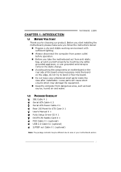
1.5 MOTHERBOARD LAYOUT KBMS 1 ATXPWR1 TA790GXE 128M CPU_ FAN1 HDMI1 S ocket A M 2+ DVI VG A PH1 PH2 PH3 PH4 DIMM A1 DIMM B1 DIMM A2 DIMM B2 USB1 RJ4 5USB1 ATXPWR2 AUDIO2 AUXPWR1 AMD 790GX JUSBV1 L AN SYS_FAN1 PEX16_ 2 PEX1 _1 PEX1 _2 BAT1 AMD SB750 SATA5-6 PEX16_ 1 SATA3-4 Co de c PCI1 Super I/O BI O S JCMOS1 SATA1-2 S PDIF1 F_AUDIO1 CD_IN1 PCI2 FDD1 IDE1 SYS_FA N2 LED_D1 LED_D2 SW_ RST JUSBV 2 F_USB 3 F_USB2 F_USB 1 PANEL1 SW_P WR Note: ■ represents the 1st pin. 5
1.5 MOTHERBOARD LAYOUT KBMS 1 ATXPWR1 TA790GXE 128M CPU_ FAN1 HDMI1 S ocket A M 2+ DVI VG A PH1 PH2 PH3 PH4 DIMM A1 DIMM B1 DIMM A2 DIMM B2 USB1 RJ4 5USB1 ATXPWR2 AUDIO2 AUXPWR1 AMD 790GX JUSBV1 L AN SYS_FAN1 PEX16_ 2 PEX1 _1 PEX1 _2 BAT1 AMD SB750 SATA5-6 PEX16_ 1 SATA3-4 Co de c PCI1 Super I/O BI O S JCMOS1 SATA1-2 S PDIF1 F_AUDIO1 CD_IN1 PCI2 FDD1 IDE1 SYS_FA N2 LED_D1 LED_D2 SW_ RST JUSBV 2 F_USB 3 F_USB2 F_USB 1 PANEL1 SW_P WR Note: ■ represents the 1st pin. 5
Setup Manual
Page 13
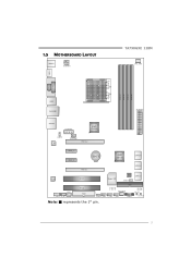
The IDE connector can connect a master and a slave drive, so you can connect up to two drives. 2 40 1 39 11 This connector supports the provided floppy drive ribbon cables. 2 34 1 33 IDE1: IDE/ATAPI Connector The motherboard has a 32-bit Enhanced IDE Controller that supports 360K, 720K, 1.2M, 1.44M and 2.88M floppy disk types. 2.4 CONNECTORS AND SLOTS TA790GXE 128M FDD1: Floppy Disk Connector The motherboard provides a standard floppy disk connector that provides PIO Mode 0~4, Bus Master, and Ultra DMA 33/66/100/133 functionality.
The IDE connector can connect a master and a slave drive, so you can connect up to two drives. 2 40 1 39 11 This connector supports the provided floppy drive ribbon cables. 2 34 1 33 IDE1: IDE/ATAPI Connector The motherboard has a 32-bit Enhanced IDE Controller that supports 360K, 720K, 1.2M, 1.44M and 2.88M floppy disk types. 2.4 CONNECTORS AND SLOTS TA790GXE 128M FDD1: Floppy Disk Connector The motherboard provides a standard floppy disk connector that provides PIO Mode 0~4, Bus Master, and Ultra DMA 33/66/100/133 functionality.
Setup Manual
Page 17
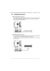
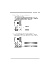
PCI-Express Gen2 supports a raw bit-rate of 5.0Gb/s on the data pins. - 2X bandwidth over the PCI-Express 1.1 architecture. PCI-Express 2.0 compliant. - PCI stands for expansion cards. TA790GXE 128M PEX1_1/PEX1_2: PCI-Express Gen2 x1 Slots - Data transfer bandwidth up to 500MB/s per direction; 1GB/s in total. - P E X 1_ 1 P E X 1_ 2 PCI1~PCI2: Peripheral Component Interconnect Slots This motherboard is a bus standard for Peripheral Component Interconnect, and it is equipped with 2 standard PCI slots. PCI1 PCI2 15 This PCI slot is designated as 32 bits.
PCI-Express Gen2 supports a raw bit-rate of 5.0Gb/s on the data pins. - 2X bandwidth over the PCI-Express 1.1 architecture. PCI-Express 2.0 compliant. - PCI stands for expansion cards. TA790GXE 128M PEX1_1/PEX1_2: PCI-Express Gen2 x1 Slots - Data transfer bandwidth up to 500MB/s per direction; 1GB/s in total. - P E X 1_ 1 P E X 1_ 2 PCI1~PCI2: Peripheral Component Interconnect Slots This motherboard is a bus standard for Peripheral Component Interconnect, and it is equipped with 2 standard PCI slots. PCI1 PCI2 15 This PCI slot is designated as 32 bits.
Setup Manual
Page 19
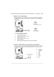
... (fused) 2 +5V (fused) 3 USB4 USB5 USB+ 6 USB+ 7 Ground 8 Ground 9 Key 10 NC 17 Set the jumper to avoid damaging the motherboard. 13 Pin 1-2 Close: Normal Operation (Default). 1 3 13 Pin 2-3 Close: Clear CMOS data. ※ Clear CMOS Procedures: 1. TA790GXE 128M JCMOS1: Clear CMOS Header Placing the jumper on the AC. 6. Remove AC power line. 2.
... (fused) 2 +5V (fused) 3 USB4 USB5 USB+ 6 USB+ 7 Ground 8 Ground 9 Key 10 NC 17 Set the jumper to avoid damaging the motherboard. 13 Pin 1-2 Close: Normal Operation (Default). 1 3 13 Pin 2-3 Close: Clear CMOS data. ※ Clear CMOS Procedures: 1. TA790GXE 128M JCMOS1: Clear CMOS Header Placing the jumper on the AC. 6. Remove AC power line. 2.
Setup Manual
Page 35
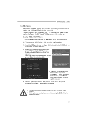
BIOS update completes. TA790GXE 128M C. Press to the USB port or the floppy disk drive. 4. BIO-Flasher BIO-Flasher is built in the BIOS chip. Insert the USB pen drive ... proceed. The utility will lead to reboot the system. Select the proper BIOS file and press then to download the latest BIOS file for the motherboard. 2. Go to the website to perform the BIOS update process. 6. A select dialog as the picture on or reset the computer and then press during the...
BIOS update completes. TA790GXE 128M C. Press to the USB port or the floppy disk drive. 4. BIO-Flasher BIO-Flasher is built in the BIOS chip. Insert the USB pen drive ... proceed. The utility will lead to reboot the system. Select the proper BIOS file and press then to download the latest BIOS file for the motherboard. 2. Go to the website to perform the BIOS update process. 6. A select dialog as the picture on or reset the computer and then press during the...
Setup Manual
Page 45
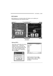
... to save file and enter file name. (We recommend that the file name should be English/number and no longer than 7 characters.) Then click Save. TA790GXE 128M BIOS Update BIOS Update is a convenient utility which allows you to complete the BIOS Backup procedure. 43 After the saving process, finish dialog will show...
... to save file and enter file name. (We recommend that the file name should be English/number and no longer than 7 characters.) Then click Save. TA790GXE 128M BIOS Update BIOS Update is a convenient utility which allows you to complete the BIOS Backup procedure. 43 After the saving process, finish dialog will show...
Setup Manual
Page 49
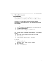
... to avoid a damage of the CPU, and the system may not power on the system again. 47 CPU fan speed is over heated, the motherboard will shutdown automatically to relief the CPU protection function. 1. Remove the power cord from power supply for seconds, that means the CPU protection function has... JCMOS1" section) 2. In this case, please double check: 1. The CPU cooler surface is rotated normally. 3. Plug in the power cord and boot up the system. TA790GXE 128M 7.2 EXTRA INFORMATION CPU Overheated If the system shutdown automatically after power on system for seconds. 2.
... to avoid a damage of the CPU, and the system may not power on the system again. 47 CPU fan speed is over heated, the motherboard will shutdown automatically to relief the CPU protection function. 1. Remove the power cord from power supply for seconds, that means the CPU protection function has... JCMOS1" section) 2. In this case, please double check: 1. The CPU cooler surface is rotated normally. 3. Plug in the power cord and boot up the system. TA790GXE 128M 7.2 EXTRA INFORMATION CPU Overheated If the system shutdown automatically after power on system for seconds. 2.
Bios Setup
Page 2
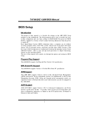
... devices such as virus and password prot ection or chipset fine-tuning options are also included in the AMI BIOS Setup program on this motherboard. T his AMI BIOS supports Version 1.1&1.2 of the Advanced Power Man agement (APM) speci fication. Sleep and Suspend power man agement... System Management Int errupt (SMI). ACPI Support AMI ACPI BIOS support Version 1.0/2.0 of Advanced Configuration and Power interface specifi cation (ACPI). TA790GXE 128M BIOS Manual BIOS Setup Introduction T he purpose of this manual is turned off. The Setup program allows users to modify the basic system...
... devices such as virus and password prot ection or chipset fine-tuning options are also included in the AMI BIOS Setup program on this motherboard. T his AMI BIOS supports Version 1.1&1.2 of the Advanced Power Man agement (APM) speci fication. Sleep and Suspend power man agement... System Management Int errupt (SMI). ACPI Support AMI ACPI BIOS support Version 1.0/2.0 of Advanced Configuration and Power interface specifi cation (ACPI). TA790GXE 128M BIOS Manual BIOS Setup Introduction T he purpose of this manual is turned off. The Setup program allows users to modify the basic system...
Bios Setup
Page 3
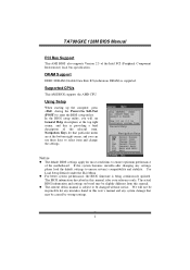
... by wrong-settings. 2 Using Setup When starting up the computer, press during the Power-On Self-Test (POST) to ensure optimum performan ce of the motherboard. z For better system perform ance, the BIOS firmware is supported. T he content of this manual is subject to be slightly different from this manual is... BIOS information and settings on board may be responsible for any mistakes found in this manual. T he default BIOS settings apply for your reference only. TA790GXE 128M BIOS Manual PCI Bus Support T his AMI BIOS supports the AMD CPU.
... by wrong-settings. 2 Using Setup When starting up the computer, press during the Power-On Self-Test (POST) to ensure optimum performan ce of the motherboard. z For better system perform ance, the BIOS firmware is supported. T he content of this manual is subject to be slightly different from this manual is... BIOS information and settings on board may be responsible for any mistakes found in this manual. T he default BIOS settings apply for your reference only. TA790GXE 128M BIOS Manual PCI Bus Support T his AMI BIOS supports the AMD CPU.

Bios Setup
Page 14
... can set the date and time at which date the system will boot up time, input hour, minute and second to enable or disable the motherboard's APIC (Advan ced Programmable Interrupt Controller). A headless server is one that operates without a keyboard, monitor or mouse. Options: Disabled (Default) / ...) / Disabled AMI OEMB table Set this value to allow the ACPIBIOS to add a pointer to enable or disabled the USB resume from Suspend mode. TA790GXE 128M BIOS Manual ACPI APIC support T his is a server-speci fic feature. Options: Disabled (Default) / Enabled Power On by PCIE/Onboard LAN T his...
... can set the date and time at which date the system will boot up time, input hour, minute and second to enable or disable the motherboard's APIC (Advan ced Programmable Interrupt Controller). A headless server is one that operates without a keyboard, monitor or mouse. Options: Disabled (Default) / ...) / Disabled AMI OEMB table Set this value to allow the ACPIBIOS to add a pointer to enable or disabled the USB resume from Suspend mode. TA790GXE 128M BIOS Manual ACPI APIC support T his is a server-speci fic feature. Options: Disabled (Default) / Enabled Power On by PCIE/Onboard LAN T his...

