Setup Manual
Page 7
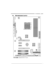
1.5 MOTHERBOARD LAYOUT KBMS 1 ATXPWR1 TA790GXE 128M CPU_ FAN1 HDMI1 S ocket A M 2+ DVI VG A PH1 PH2 PH3 PH4 DIMM A1 DIMM B1 DIMM A2 DIMM B2 USB1 RJ4 5USB1 ATXPWR2 AUDIO2 AUXPWR1 AMD 790GX JUSBV1 L AN SYS_FAN1 PEX16_ 2 PEX1 _1 PEX1 _2 BAT1 AMD SB750 SATA5-6 PEX16_ 1 SATA3-4 Co de c PCI1 Super I/O BI O S JCMOS1 SATA1-2 S PDIF1 F_AUDIO1 CD_IN1 PCI2 FDD1 IDE1 SYS_FA N2 LED_D1 LED_D2 SW_ RST JUSBV 2 F_USB 3 F_USB2 F_USB 1 PANEL1 SW_P WR Note: ■ represents the 1st pin. 5
1.5 MOTHERBOARD LAYOUT KBMS 1 ATXPWR1 TA790GXE 128M CPU_ FAN1 HDMI1 S ocket A M 2+ DVI VG A PH1 PH2 PH3 PH4 DIMM A1 DIMM B1 DIMM A2 DIMM B2 USB1 RJ4 5USB1 ATXPWR2 AUDIO2 AUXPWR1 AMD 790GX JUSBV1 L AN SYS_FAN1 PEX16_ 2 PEX1 _1 PEX1 _2 BAT1 AMD SB750 SATA5-6 PEX16_ 1 SATA3-4 Co de c PCI1 Super I/O BI O S JCMOS1 SATA1-2 S PDIF1 F_AUDIO1 CD_IN1 PCI2 FDD1 IDE1 SYS_FA N2 LED_D1 LED_D2 SW_ RST JUSBV 2 F_USB 3 F_USB2 F_USB 1 PANEL1 SW_P WR Note: ■ represents the 1st pin. 5
Setup Manual
Page 11
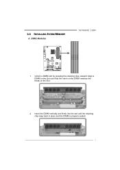
Align a DIMM on the slot such that the notch on the DIMM matches the break on the Slot. 2. Unlock a DIMM slot by pressing the retaining clips outward. DDR2 Modules TA790GXE 128M D IM M A1 D IM M B1 D IM M A2 D IM M B2 1. Insert the DIMM vertically and firmly into the slot until the retaining chip snap back in place and the DIMM is properly seated. 9 2.3 INSTALLING SYSTEM MEMORY A.
Align a DIMM on the slot such that the notch on the DIMM matches the break on the Slot. 2. Unlock a DIMM slot by pressing the retaining clips outward. DDR2 Modules TA790GXE 128M D IM M A1 D IM M B1 D IM M A2 D IM M B2 1. Insert the DIMM vertically and firmly into the slot until the retaining chip snap back in place and the DIMM is properly seated. 9 2.3 INSTALLING SYSTEM MEMORY A.
