
P4VMA-M user's manual
Page 1
C. CE Mark This equipment is in conformity with the instructions, may cause harmful interference to radio communications. FCC Statement This equipment has been tested and found to comply with the limits for help. * All external cables connecting to this basic unit must be determined by turning the equipment off and on, the user is encouraged to try to correct the interference by one or more of the following measures: * Reorient or relocate the receiving antenna. * Increase the separation between the equipment and receiver. * Connect the equipment into an outlet on a circuit different ...
C. CE Mark This equipment is in conformity with the instructions, may cause harmful interference to radio communications. FCC Statement This equipment has been tested and found to comply with the limits for help. * All external cables connecting to this basic unit must be determined by turning the equipment off and on, the user is encouraged to try to correct the interference by one or more of the following measures: * Reorient or relocate the receiving antenna. * Increase the separation between the equipment and receiver. * Connect the equipment into an outlet on a circuit different ...
P4VMA-M user's manual
Page 2
The software described in this document is furnished under a license and may be reproduced or transmitted in any form or by any means, electronic or mechanical, photocopying, recording or otherwise, stored in any retrieval system of any errors that is not supplied by the manufacturer. Copyright Notice No part of this manual may be construed as a commitment by the manufacturer or its affiliated companies. Trademark Other product and company names mentioned herein may be used or copied only in accordance with the terms of the manufacturer. ATI is registered trademark of their ...
The software described in this document is furnished under a license and may be reproduced or transmitted in any form or by any means, electronic or mechanical, photocopying, recording or otherwise, stored in any retrieval system of any errors that is not supplied by the manufacturer. Copyright Notice No part of this manual may be construed as a commitment by the manufacturer or its affiliated companies. Trademark Other product and company names mentioned herein may be used or copied only in accordance with the terms of the manufacturer. ATI is registered trademark of their ...
P4VMA-M user's manual
Page 3
Please keep this equipment in an environment unconditioned, storage temperature above 40°C, it may damage the equipment. 8. Don't use for cleaning. Lay this equipment from mains to user's manual. The openings on a reliable surface when install. Make sure the voltage of the cord should be greater than the voltage and current rating marked on the equipment should only open the equipment. f. The voltage and current rating of the power source when connect the equipment to moisture. Never open the equipment. 15. If one of breakage 3 English The ...
Please keep this equipment in an environment unconditioned, storage temperature above 40°C, it may damage the equipment. 8. Don't use for cleaning. Lay this equipment from mains to user's manual. The openings on a reliable surface when install. Make sure the voltage of the cord should be greater than the voltage and current rating marked on the equipment should only open the equipment. f. The voltage and current rating of the power source when connect the equipment to moisture. Never open the equipment. 15. If one of breakage 3 English The ...
P4VMA-M user's manual
Page 4
Layout of Contents FCC Statement 1 C. Hardware 8 B. Installation and Setup 11 Francais Caracteristiques de P4VMA-M 19 Trouble Shooting 22 WarpSpeeder 24 TM ...StudioFun!TM (Optional 32 English 4 C. P4VMA-M System Structure 6 Section 4. P4VMA-M Features 8 A. D. Package contents 10 Section 6. BIOS & Software 9 Section 5. Table of P4VMA-M V.2.x 5 Section 2. Layout of P4VMA-M V.7.x 6 Section 3. Statement 1 CE Mark 1 Overview 2 Copyright Notice 2 Trademark 2 Important Safety Information 3 English Section 1.
Layout of Contents FCC Statement 1 C. Hardware 8 B. Installation and Setup 11 Francais Caracteristiques de P4VMA-M 19 Trouble Shooting 22 WarpSpeeder 24 TM ...StudioFun!TM (Optional 32 English 4 C. P4VMA-M System Structure 6 Section 4. P4VMA-M Features 8 A. D. Package contents 10 Section 6. BIOS & Software 9 Section 5. Table of P4VMA-M V.2.x 5 Section 2. Layout of P4VMA-M V.7.x 6 Section 3. Statement 1 CE Mark 1 Overview 2 Copyright Notice 2 Trademark 2 Important Safety Information 3 English Section 1.
P4VMA-M user's manual
Page 5
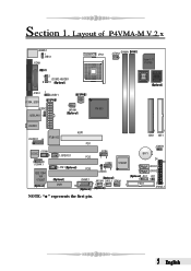
Layout of P4VMA-M V.2.x JKBMS1 1 JKBV1 JCOM1 Socket 478 CPU1 JCFAN1 DIMM1 1 Super I/O IT 8705 12 JCOM2-HEADER 9 10 JVGA1 1 JUSBV1 J1394_USB1 JUSBV2 JUSBLAN1 1 1 JNFAN1 PM 800 JAUDIO JAUDIO1 14 1 RTL8100C AGP1 PCI1 CODEC JCDIN1 1 1 9 J1394A1 IEEE 1394 VIA VT 6307 1 JSPDIFO1 1 JFM1 JUSB4 PCI2 19 JUSB3 VT 8237 1 PCI3 19 JUSBV3 CNR1 JGAME1 JWOM1 JWOL1 JSFAN1 16 11 1 1 1 NOTE: " " represents the first pin. BIOS BIOS 1 1 IDE2 IDE1 JCMOS1 1 BAT1 24 23 1 JSATA1 1 JSATA2 JDJ1 1 FDD1 JCI1 1 21 JPANEL1 5 English Section 1.
Layout of P4VMA-M V.2.x JKBMS1 1 JKBV1 JCOM1 Socket 478 CPU1 JCFAN1 DIMM1 1 Super I/O IT 8705 12 JCOM2-HEADER 9 10 JVGA1 1 JUSBV1 J1394_USB1 JUSBV2 JUSBLAN1 1 1 JNFAN1 PM 800 JAUDIO JAUDIO1 14 1 RTL8100C AGP1 PCI1 CODEC JCDIN1 1 1 9 J1394A1 IEEE 1394 VIA VT 6307 1 JSPDIFO1 1 JFM1 JUSB4 PCI2 19 JUSB3 VT 8237 1 PCI3 19 JUSBV3 CNR1 JGAME1 JWOM1 JWOL1 JSFAN1 16 11 1 1 1 NOTE: " " represents the first pin. BIOS BIOS 1 1 IDE2 IDE1 JCMOS1 1 BAT1 24 23 1 JSATA1 1 JSATA2 JDJ1 1 FDD1 JCI1 1 21 JPANEL1 5 English Section 1.
P4VMA-M user's manual
Page 6
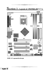
DIMM1 1 1 IDE1 IDE2 BAT1 JUSB3 19 VT 8237 1 JSATA1 JUSB4 19 JSATA2 1 JSFAN1 1 2 1 JCI1 1 JCMOS1 JPANEL1 1 24 23 English 6 Section 2. Layout of P4VMA-M V.7.x JKBMS1 JCOM1 Socket 478 CPU1 1 JCFAN1 JVGA1 JUSB1 JUSBLAN1 JAUDIO Super I/O IT 8705 BIOS VT 6103 1 14 JAUDIO1 JCDIN1 1 CODEC JSPDIFO1 1 (Optional) CNR1 PM 800 AGP1 PCI1 PCI2 PCI3 1 FDD1 NOTE: " " represents the first pin.
DIMM1 1 1 IDE1 IDE2 BAT1 JUSB3 19 VT 8237 1 JSATA1 JUSB4 19 JSATA2 1 JSFAN1 1 2 1 JCI1 1 JCMOS1 JPANEL1 1 24 23 English 6 Section 2. Layout of P4VMA-M V.7.x JKBMS1 JCOM1 Socket 478 CPU1 1 JCFAN1 JVGA1 JUSB1 JUSBLAN1 JAUDIO Super I/O IT 8705 BIOS VT 6103 1 14 JAUDIO1 JCDIN1 1 CODEC JSPDIFO1 1 (Optional) CNR1 PM 800 AGP1 PCI1 PCI2 PCI3 1 FDD1 NOTE: " " represents the first pin.
P4VMA-M user's manual
Page 8
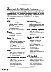
... master slots. * One AGP 4X/8X compatible slot. * One CNR slot. (optional) LAN PHY(optional for v7.x) * Chip: VT6103 * Support 10 Mb/s, 100 Mb/s auto- P4VMA-M Features In this section, you a quick and correct installation of your computer, including its features, various jumpers, headers, connectors, and also the installation guide to...
... master slots. * One AGP 4X/8X compatible slot. * One CNR slot. (optional) LAN PHY(optional for v7.x) * Chip: VT6103 * Support 10 Mb/s, 100 Mb/s auto- P4VMA-M Features In this section, you a quick and correct installation of your computer, including its features, various jumpers, headers, connectors, and also the installation guide to...
P4VMA-M user's manual
Page 9
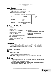
Total Memory Size with 360K, 720K, 1.2M, 1.44M and 2.88Mbytes. - 4 x USB2.0 ports. - 1 S/PDIF-Out connector (optional) Dimension * Micro ATX Form Factor: 24.4 cm x 24.4 cm. (W x L) (for version 2.0) * Micro ATX Form Factor: 19.9 cm x 24.4 cm. (W x L) (for Windows 98SE, Windows ME, Windows 2000, Windows XP, Linux, UNIX series, etc. 9 English BIOS & Software BIOS * Award legal BIOS. * Supports APM1.2, ACPI, USB Function. * The BIOS configuration manual can be found in vertical. - 1 x RJ-45 LAN jack. - 1 x PS/2 mouse and PS/2 keyboard. - 4 x USB2.0 ports. - 1 x IEEE 1394 FirewireTM port (...
Total Memory Size with 360K, 720K, 1.2M, 1.44M and 2.88Mbytes. - 4 x USB2.0 ports. - 1 S/PDIF-Out connector (optional) Dimension * Micro ATX Form Factor: 24.4 cm x 24.4 cm. (W x L) (for version 2.0) * Micro ATX Form Factor: 19.9 cm x 24.4 cm. (W x L) (for Windows 98SE, Windows ME, Windows 2000, Windows XP, Linux, UNIX series, etc. 9 English BIOS & Software BIOS * Award legal BIOS. * Supports APM1.2, ACPI, USB Function. * The BIOS configuration manual can be found in vertical. - 1 x RJ-45 LAN jack. - 1 x PS/2 mouse and PS/2 keyboard. - 4 x USB2.0 ports. - 1 x IEEE 1394 FirewireTM port (...
P4VMA-M user's manual
Page 10
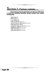
Section 5. If there are anything missing, please contact your DIY action. Application CD X1 (optional) * S/PDIF-Out Cable X 1 (optional) * IEEE 1394 Cable X 1 (optional) * Serial ATA Cable X 2 (optional) English 10 Package contents Check what you have bought before you start your dealer immediately. * HDD Cable X 1 * FDD Cable X 1 * User's Manual X1 * USB 2.0 Cable X1 (optional) * Rear I/O Panel for ATX Case X1 (optional) * Fully Setup Driver CD X1 * StudioFun!
Section 5. If there are anything missing, please contact your DIY action. Application CD X1 (optional) * S/PDIF-Out Cable X 1 (optional) * IEEE 1394 Cable X 1 (optional) * Serial ATA Cable X 2 (optional) English 10 Package contents Check what you have bought before you start your dealer immediately. * HDD Cable X 1 * FDD Cable X 1 * User's Manual X1 * USB 2.0 Cable X1 (optional) * Rear I/O Panel for ATX Case X1 (optional) * Fully Setup Driver CD X1 * StudioFun!
P4VMA-M user's manual
Page 11
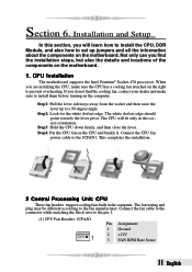
Step1: Pull the lever sideways away from the socket and then raise the lever up jumpers and all the information about the components on the motherboard. The CPU will learn how to install the CPU, DDR Module, and also how to set up to a 90-degree angle. Step4: Put the CPU fan on the motherboard. 1. Connect the CPU fan power cable to the fan manufacturer. When you do not find the installation steps, but also the details and locations of the components on the CPU and buckle it. Step2: Look for the white dot/cut edge should point towards the lever pivot. Step3: Hold the ...
Step1: Pull the lever sideways away from the socket and then raise the lever up jumpers and all the information about the components on the motherboard. The CPU will learn how to install the CPU, DDR Module, and also how to set up to a 90-degree angle. Step4: Put the CPU fan on the motherboard. 1. Connect the CPU fan power cable to the fan manufacturer. When you do not find the installation steps, but also the details and locations of the components on the CPU and buckle it. Step2: Look for the white dot/cut edge should point towards the lever pivot. Step3: Hold the ...
P4VMA-M user's manual
Page 12
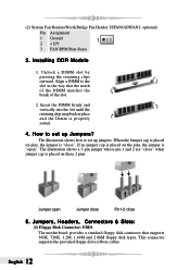
Unlock a DIMM slot by pressing the retaining clips outward. Jumpers, Headers, Connectors & Slots: (1) Floppy Disk Connector: FDD1 The motherboard provides a standard floppy disk connector that the notch of the DIMM matches the break of the slot. 2. This connector supports the provided floppy drive ribbon cables. Insert the DIMM firmly and vertically into the slot until the retaining chip snap back in the way that supports 360K, 720K, 1.2M, 1.44M and 2.88M floppy disk types. If no jumper cap is placed on pins, the jumper is "open Jumper close Pin1-2 close " when jumper cap is ...
Unlock a DIMM slot by pressing the retaining clips outward. Jumpers, Headers, Connectors & Slots: (1) Floppy Disk Connector: FDD1 The motherboard provides a standard floppy disk connector that the notch of the DIMM matches the break of the slot. 2. This connector supports the provided floppy drive ribbon cables. Insert the DIMM firmly and vertically into the slot until the retaining chip snap back in the way that supports 360K, 720K, 1.2M, 1.44M and 2.88M floppy disk types. If no jumper cap is placed on pins, the jumper is "open Jumper close Pin1-2 close " when jumper cap is ...
P4VMA-M user's manual
Page 13
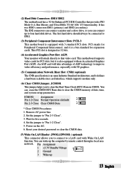
(2) Hard Disk Connectors: IDE1/ IDE2 The motherboard has a 32-bit Enhanced PCI IDE Controller that video card. An AGP card will attach directly to that provides PIO Mode 0~4, Bus Master, and Ultra DMA 33/ 66/ 100/ 133 functionality. Set the jumper to "Pin 2-3 Close". 3. PCI stands for expansion cards. Remove AC power line. 2. The first hard drive should always be connected to clear the Real Time Clock (RTC) Ram in CMOS. Reset your desired password or clear the CMOS data. (7) Wake On LAN Header: JWOL1/JWOM1 ( optional) This connector allows you to connect to a LAN...
(2) Hard Disk Connectors: IDE1/ IDE2 The motherboard has a 32-bit Enhanced PCI IDE Controller that video card. An AGP card will attach directly to that provides PIO Mode 0~4, Bus Master, and Ultra DMA 33/ 66/ 100/ 133 functionality. Set the jumper to "Pin 2-3 Close". 3. PCI stands for expansion cards. Remove AC power line. 2. The first hard drive should always be connected to clear the Real Time Clock (RTC) Ram in CMOS. Reset your desired password or clear the CMOS data. (7) Wake On LAN Header: JWOL1/JWOM1 ( optional) This connector allows you to connect to a LAN...
P4VMA-M user's manual
Page 14
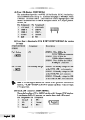
Pin Assignment Pin Assignment 1 +5V(fused) 2 +5V(fused) 3 USBP-0 5 USBP+0 4 USBP-1 6 USBP+1 19 7 Ground 8 Ground 9 KEY 10 NC (9) Power Source Selection for USB: JUSBV1/JUSBV2/JUSBV3 (for version 2.0 only) JUSBV1/JUSBV2 Assignment Description JUSBV3 Pin 1-2 close 1 +5V Standby Voltage JUSBV1: 5V Standby voltage for USB at the J1394_USB1 port connector. JUSBV3: 5V Standby voltage for USB at the JUSB3/JUSB4 port connectors. Note: In order to support the function "Power-on the system via USB devices function," " JUSBV1/JUSBV2/ JUSBV3" jumper cap should be placed on pin 2-3 ...
Pin Assignment Pin Assignment 1 +5V(fused) 2 +5V(fused) 3 USBP-0 5 USBP+0 4 USBP-1 6 USBP+1 19 7 Ground 8 Ground 9 KEY 10 NC (9) Power Source Selection for USB: JUSBV1/JUSBV2/JUSBV3 (for version 2.0 only) JUSBV1/JUSBV2 Assignment Description JUSBV3 Pin 1-2 close 1 +5V Standby Voltage JUSBV1: 5V Standby voltage for USB at the J1394_USB1 port connector. JUSBV3: 5V Standby voltage for USB at the JUSB3/JUSB4 port connectors. Note: In order to support the function "Power-on the system via USB devices function," " JUSBV1/JUSBV2/ JUSBV3" jumper cap should be placed on pin 2-3 ...

P4VMA-M user's manual
Page 15
Pin Assignment 1 Left Channel Input 2 Ground 3 Ground 1 4 Right Channel Input (12) Front Panel Connector: JPANEL1 The connector is for keyboard and mouse 1 Pin 2-3 close +5V 5V for electrical connection to receive stereo audio input from sound sources, such as CD-ROM, TV Tuner, MPEG card, etc. PWR_LED S LP (+) (+)(-)O N/ OF F I R 2 24 1 23 (+) (-) SPK HLED RST IR Pin Assignment Function Pin Assignment Function 1 +5V Speaker 2 Sleep Control SleepButton 3 NA Connector 4 Ground 5 NA 6 NA NA 7 Speaker 8 Power LED (+) POWER LED 9 HDD LED (+) Hard DriveLED ...
Pin Assignment 1 Left Channel Input 2 Ground 3 Ground 1 4 Right Channel Input (12) Front Panel Connector: JPANEL1 The connector is for keyboard and mouse 1 Pin 2-3 close +5V 5V for electrical connection to receive stereo audio input from sound sources, such as CD-ROM, TV Tuner, MPEG card, etc. PWR_LED S LP (+) (+)(-)O N/ OF F I R 2 24 1 23 (+) (-) SPK HLED RST IR Pin Assignment Function Pin Assignment Function 1 +5V Speaker 2 Sleep Control SleepButton 3 NA Connector 4 Ground 5 NA 6 NA NA 7 Speaker 8 Power LED (+) POWER LED 9 HDD LED (+) Hard DriveLED ...
P4VMA-M user's manual
Page 16
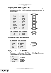
(14) Power Connector: JATXPWR1/JATXPWR2 The motherboard supports ATX power supply for digital audio transmission. Before installing the power supply connector, please make sure that all components are installed properly. PIN Assignment PIN Assignment 10 20 1 +3.3V 11 +3.3V 2 +3.3V 12 -12V 3 Ground 13 Ground 4 +5V 14 PS_ON 5 Ground 15 Ground 6 +5V 16 Ground 7 Ground 17 Ground 8 PW_OK 18 -5V 9 +5V_SB 10 +12V 19 +5V 20 +5V 1 11 PIN Assignment PIN Assignment 1 +12V 3 Ground 2 1 2 +12V 4 Ground (15) Front 1394 Header: J1394A1 (optional) Pin Assignment Pin ...
(14) Power Connector: JATXPWR1/JATXPWR2 The motherboard supports ATX power supply for digital audio transmission. Before installing the power supply connector, please make sure that all components are installed properly. PIN Assignment PIN Assignment 10 20 1 +3.3V 11 +3.3V 2 +3.3V 12 -12V 3 Ground 13 Ground 4 +5V 14 PS_ON 5 Ground 15 Ground 6 +5V 16 Ground 7 Ground 17 Ground 8 PW_OK 18 -5V 9 +5V_SB 10 +12V 19 +5V 20 +5V 1 11 PIN Assignment PIN Assignment 1 +12V 3 Ground 2 1 2 +12V 4 Ground (15) Front 1394 Header: J1394A1 (optional) Pin Assignment Pin ...

P4VMA-M user's manual
Page 17
Pin Assignment Pin Assignment 1 Mic In/Center 2 Ground 3 Mic Power/Bass 4 Audio Power 5 RT Line Out/Speaker 6 RT Line Out/ Out Right 7 Reserved Speaker Out Right 8 Key 14 9 LFT Line Out/Speaker 10 LFT Line Out/ 1 Out Left Speaker Out Left 11 RT Line In/Rear 12 RT Line In/Rear Speaker Right Speaker Right 13 LFT Line In/Rear 14 LFT Line In/ Speaker Left Rear Speaker Left (19) AUDIO DJ Connector: JDJ1 (optional) Pin Assignment Pin Assignment 1 SMBDATA 2 SMBCLK 3 INT_B 4 KEY 5 ATX_PWROK JDJ1 1 (20) COM2 Header: JCOM2-HEADER (optional) Pin Assignment 1 RIN1 3 DOUT2 ...
Pin Assignment Pin Assignment 1 Mic In/Center 2 Ground 3 Mic Power/Bass 4 Audio Power 5 RT Line Out/Speaker 6 RT Line Out/ Out Right 7 Reserved Speaker Out Right 8 Key 14 9 LFT Line Out/Speaker 10 LFT Line Out/ 1 Out Left Speaker Out Left 11 RT Line In/Rear 12 RT Line In/Rear Speaker Right Speaker Right 13 LFT Line In/Rear 14 LFT Line In/ Speaker Left Rear Speaker Left (19) AUDIO DJ Connector: JDJ1 (optional) Pin Assignment Pin Assignment 1 SMBDATA 2 SMBCLK 3 INT_B 4 KEY 5 ATX_PWROK JDJ1 1 (20) COM2 Header: JCOM2-HEADER (optional) Pin Assignment 1 RIN1 3 DOUT2 ...

P4VMA-M user's manual
Page 18
(21) Game Header: JGAME1 (optional) 16 1 Pin Assignment Pin Assignment 1 +5V 2 +5V 3 Joystick B Button 1 4 Joystick A Button 1 5 Joystick B Coordinate X 6 Joystick A Coordinate X 7 MIDI Output 8 Ground 9 Joystick B Coordinate Y 10 Ground 11 Joystick B Button 2 12 Joystick A Coordinate Y 13 MIDI Input 14 Joystick A Button 2 15 NA 16 +5V (22) Back Panel Connectors 6 Channel Speakers Speaker Out/ Right & Left Line In/ Rear Speaker (Left & Right) Mic In/ Center & Bass English 18
(21) Game Header: JGAME1 (optional) 16 1 Pin Assignment Pin Assignment 1 +5V 2 +5V 3 Joystick B Button 1 4 Joystick A Button 1 5 Joystick B Coordinate X 6 Joystick A Coordinate X 7 MIDI Output 8 Ground 9 Joystick B Coordinate Y 10 Ground 11 Joystick B Button 2 12 Joystick A Coordinate Y 13 MIDI Input 14 Joystick A Button 2 15 NA 16 +5V (22) Back Panel Connectors 6 Channel Speakers Speaker Out/ Right & Left Line In/ Rear Speaker (Left & Right) Mic In/ Center & Bass English 18
P4VMA-M user's manual
Page 22
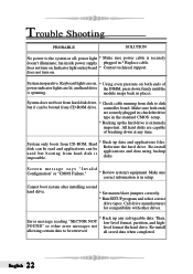
Keyboard lights are on, * Using even pressure on . Hard disk can be read and applications can be booted from CD-ROM drive. Reformat the hard drive. Screen message says "Invalid Configuration" or "CMOS Failure." * Review system's equipment. Then, Error message reading "SECTOR NOT low-level format, partition, and high- English 22 Indicator light on . System only boots from hard disk is impossible. * Back up data and applications files. FOUND" or other drives. * Back up the hard drive is in places. Re-install applications and data using backup disks. Re-install...
Keyboard lights are on, * Using even pressure on . Hard disk can be read and applications can be booted from CD-ROM drive. Reformat the hard drive. Screen message says "Invalid Configuration" or "CMOS Failure." * Review system's equipment. Then, Error message reading "SECTOR NOT low-level format, partition, and high- English 22 Indicator light on . System only boots from hard disk is impossible. * Back up data and applications files. FOUND" or other drives. * Back up the hard drive is in places. Re-install applications and data using backup disks. Re-install...
P4VMA-M user's manual
Page 23
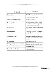
Check keys again. If no color still, replace monitor. If no improvement, replace keyboard. Certain keys do not function. * Replace keyboard. Missing operating system on screen. * If possible, connect monitor to system. Screen goes blank periodically. * Check the power connectors to monitor and to another system. Keyboard failure. * Reconnect keyborad. No display on hard drive. * Run setup and select correct drive type. C: drive failure. * Check hard drive cable. Reinstall memory, and make sure that all memory modules are installed in correct sockets. Computer ...
Check keys again. If no color still, replace monitor. If no improvement, replace keyboard. Certain keys do not function. * Replace keyboard. Missing operating system on screen. * If possible, connect monitor to system. Screen goes blank periodically. * Check the power connectors to monitor and to another system. Keyboard failure. * Reconnect keyborad. No display on hard drive. * Run setup and select correct drive type. C: drive failure. * Check hard drive cable. Reinstall memory, and make sure that all memory modules are installed in correct sockets. Computer ...
P4VMA-M user's manual
Page 24
Also, in system fail or hang, [ WarpSpeederTM ] technology assures the system stability by automatically rebooting the computer and then restart to a speed that is not appropriate when testing and results in the About panel, you do not need to power up . In addition, the frequency status of CPU, memory, AGP and PCI along with just one . If you use Windows XP, you can get detail descriptions about BIOS model and chipsets. English 24 System Requirement OS Support: Windows 98 SE, Windows Me, Windows 2000, Windows XP DirectX: DirectX 8.1 or above. (The Windows XP operating system ...
Also, in system fail or hang, [ WarpSpeederTM ] technology assures the system stability by automatically rebooting the computer and then restart to a speed that is not appropriate when testing and results in the About panel, you do not need to power up . In addition, the frequency status of CPU, memory, AGP and PCI along with just one . If you use Windows XP, you can get detail descriptions about BIOS model and chipsets. English 24 System Requirement OS Support: Windows 98 SE, Windows Me, Windows 2000, Windows XP DirectX: DirectX 8.1 or above. (The Windows XP operating system ...