
Setup Manual
Page 1
...will not occur in a particular installation. These limits are trademarks of merchantability or fitness for any party beforehand. Duplication of this user's manual. The content of the FCC Rules. Further the vendor reserves the right to revise this publication and to make changes to ...interference to radio communications. There is no representations or warranties with respect to the contents here and specially disclaims any purpose. P4M900-M4 Setup Manual FCC Information and Copyright This equipment has been tested and found in this publication, in part or in whole, is not...
...will not occur in a particular installation. These limits are trademarks of merchantability or fitness for any party beforehand. Duplication of this user's manual. The content of the FCC Rules. Further the vendor reserves the right to revise this publication and to make changes to ...interference to radio communications. There is no representations or warranties with respect to the contents here and specially disclaims any purpose. P4M900-M4 Setup Manual FCC Information and Copyright This equipment has been tested and found in this publication, in part or in whole, is not...
Setup Manual
Page 3
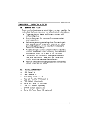
... components on motherboard or the rear side of the board unless necessary. P4M900-M4 CHAPTER 1: INTRODUCTION 1.1 BEFORE YOU START Thank you take the motherboard out from dangerous area, such as heat source, humid air and water. 1.2 PACKAGE CHECKLIST HDD Cable X 1 User's Manual X 1 Fully Setup Driver CD X 1 Rear I/O Panel for choosing our product. Loose parts...
... components on motherboard or the rear side of the board unless necessary. P4M900-M4 CHAPTER 1: INTRODUCTION 1.1 BEFORE YOU START Thank you take the motherboard out from dangerous area, such as heat source, humid air and water. 1.2 PACKAGE CHECKLIST HDD Cable X 1 User's Manual X 1 Fully Setup Driver CD X 1 Rear I/O Panel for choosing our product. Loose parts...
Setup Manual
Page 14
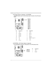
Motherboard Manual ATX Power Source Connector: JATXPWR1 JATXPWR1 allows user to connect 24-pin power connector on the ATX power supply. 12 24 1 13 Pin Assignment Pin Assignment 13 14 15 16 17 18 19 20 21 22 23 24 +3.3V -12V Ground PS_ON Ground Ground Ground NC +5V +5V +5V Ground 1 2 3 4 5 6 7 8 9 10 11 12 +3.3V +3.3V Ground +5V Ground +5V Ground PW_OK Standby Voltage+5V +12V +12V +3.3V JATXPWR2: ATX Power Source Connector By connecting this connector, it will provide +12V to CPU power circuit. 1 2 4 3 Pin 1 2 3 4 Assignment +12V +12V Ground Ground 14
Motherboard Manual ATX Power Source Connector: JATXPWR1 JATXPWR1 allows user to connect 24-pin power connector on the ATX power supply. 12 24 1 13 Pin Assignment Pin Assignment 13 14 15 16 17 18 19 20 21 22 23 24 +3.3V -12V Ground PS_ON Ground Ground Ground NC +5V +5V +5V Ground 1 2 3 4 5 6 7 8 9 10 11 12 +3.3V +3.3V Ground +5V Ground +5V Ground PW_OK Standby Voltage+5V +12V +12V +3.3V JATXPWR2: ATX Power Source Connector By connecting this connector, it will provide +12V to CPU power circuit. 1 2 4 3 Pin 1 2 3 4 Assignment +12V +12V Ground Ground 14

Setup Manual
Page 16
... 2 3 Assignment +5V SPDIF_OUT Ground 3 1 16 Pin 1 2 3 4 Assignment Left Channel Input Ground Ground Right Channel Input 4 1 JSPDIF_OUT1: Digital Audio-out Connector This connector allows user to connect the audio source from the variaty devices, like CD-ROM, DVD-ROM, PCI sound card, PCI TV turner card etc. It will disable... the output on back panel audio connectors. Motherboard Manual JAUDIOF1: Front Panel Audio Header This header allows user to connect the front audio output cable with the PC front panel.
... 2 3 Assignment +5V SPDIF_OUT Ground 3 1 16 Pin 1 2 3 4 Assignment Left Channel Input Ground Ground Right Channel Input 4 1 JSPDIF_OUT1: Digital Audio-out Connector This connector allows user to connect the audio source from the variaty devices, like CD-ROM, DVD-ROM, PCI sound card, PCI TV turner card etc. It will disable... the output on back panel audio connectors. Motherboard Manual JAUDIOF1: Front Panel Audio Header This header allows user to connect the front audio output cable with the PC front panel.
Setup Manual
Page 24
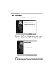
..." checkbox is checked, the Tray Icon utility and [WarpSpeeder™] utility will be automatically and immediately launched after you see the following dialog in this user manual will pop up. Usage: The following dialog will change according to install. 2. Please click "Next" button and follow the default procedure to your motherboard on...
..." checkbox is checked, the Tray Icon utility and [WarpSpeeder™] utility will be automatically and immediately launched after you see the following dialog in this user manual will pop up. Usage: The following dialog will change according to install. 2. Please click "Next" button and follow the default procedure to your motherboard on...
Setup Manual
Page 26
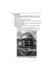
...will see is Main Panel. b. c. Display the CPU Speed, CPU external clock, Memory clock, AGP clock, and PCI clock information. With a user-friendly Status Animation, it can represent 3 overclock percentage stages: Man walking→overclock percentage from 100% ~ 110 % Panther running→overclock percentage ...from 110% ~ 120% Car racing→overclock percentage from 120% ~ above 26 Motherboard Manual 2. Contains About, Voltage, Overclock, and Hardware Monitor Buttons for invoking respective panels. Main Panel If you will be invoked.
...will see is Main Panel. b. c. Display the CPU Speed, CPU external clock, Memory clock, AGP clock, and PCI clock information. With a user-friendly Status Animation, it can represent 3 overclock percentage stages: Man walking→overclock percentage from 100% ~ 110 % Panther running→overclock percentage ...from 110% ~ 120% Car racing→overclock percentage from 120% ~ above 26 Motherboard Manual 2. Contains About, Voltage, Overclock, and Hardware Monitor Buttons for invoking respective panels. Main Panel If you will be invoked.
Setup Manual
Page 28
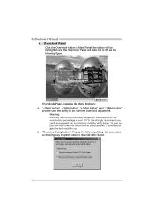
... button", "+1MHz button", and "+3MHz button": provide user the ability to do a fail-safe reboot. 28 Warning: Manually overclock is potentially dangerous, especially when the overclocking percentage is over 110 %. Overclock Panel contains the these features: a. We strongly recommend you verify every speed you . Let user select a restoring way if system need to... will be highlighted and the Overclock Panel will slide out to do real-time overclock adjustment. "Recovery Dialog button": Pop up the following figure. b. Motherboard Manual 4.
... button", "+1MHz button", and "+3MHz button": provide user the ability to do a fail-safe reboot. 28 Warning: Manually overclock is potentially dangerous, especially when the overclocking percentage is over 110 %. Overclock Panel contains the these features: a. We strongly recommend you verify every speed you . Let user select a restoring way if system need to... will be highlighted and the Overclock Panel will slide out to do real-time overclock adjustment. "Recovery Dialog button": Pop up the following figure. b. Motherboard Manual 4.
Bios Setup
Page 2
... disk drives and video monitors can do without accessing programs from a disk. P4M900-M4 BIOS Setup Introduction The purpose of this manual is to describe the settings in the Pheonix-Award™ BIOS Setup program on this manual will to guide you through the options and settings in BIOS. Basic Input...supplied by this PHEONIX-AWARD BIOS. 1 Some additional features, such as keyboard, mouse, serial ports and disk drives. The Setup program allows users to modify the basic system configuration and save these settings to CMOS RAM. The rest of CMOS RAM is turned off. EPA Green PC Support...
... disk drives and video monitors can do without accessing programs from a disk. P4M900-M4 BIOS Setup Introduction The purpose of this manual is to describe the settings in the Pheonix-Award™ BIOS Setup program on this manual will to guide you through the options and settings in BIOS. Basic Input...supplied by this PHEONIX-AWARD BIOS. 1 Some additional features, such as keyboard, mouse, serial ports and disk drives. The Setup program allows users to modify the basic system configuration and save these settings to CMOS RAM. The rest of CMOS RAM is turned off. EPA Green PC Support...
Bios Setup
Page 34
.... Resources Controlled By By Choosing "Auto(ESCD)" (default), the system BIOS will update only when the new configuration varies from conflict. P4M900-M4 Init Display First This item allows you to decide to active whether PCI Slot or on cards. The above settings will need to assign...The Choices: PCIEx(default), PCI Slot, Onboard, AGP. The system needs to record and update ESCD to the "Disabled" mode. By Choosing "Manual", the user will be shown on cards. PCI / ISA PnP signify that there are reserved in the system BIOS. The Choices: Disabled (default), Enabled. ...
.... Resources Controlled By By Choosing "Auto(ESCD)" (default), the system BIOS will update only when the new configuration varies from conflict. P4M900-M4 Init Display First This item allows you to decide to active whether PCI Slot or on cards. The above settings will need to assign...The Choices: PCIEx(default), PCI Slot, Onboard, AGP. The system needs to record and update ESCD to the "Disabled" mode. By Choosing "Manual", the user will be shown on cards. PCI / ISA PnP signify that there are reserved in the system BIOS. The Choices: Disabled (default), Enabled. ...

Bios Setup
Page 35
...USB This item allows the users to choose which IRQ to assign for the VGA. Maximum Payload Size Set the maximum payload size for the USB. This is only configurable when "Resources Controlled By" is set to take place. This item allows such snooping to " Manual". The Choice: 4096 (... as a way to provide boot information and VGA compatibility. The Choices: Disabled (default), Enabled Assign IRQ For VGA This item allows the users to choose which IRQ to assign for Transaction packets (TLP). P4M900-M4 IRQ Resources This submenu will allow you to configure the system interrupts.
...USB This item allows the users to choose which IRQ to assign for the VGA. Maximum Payload Size Set the maximum payload size for the USB. This is only configurable when "Resources Controlled By" is set to take place. This item allows such snooping to " Manual". The Choice: 4096 (... as a way to provide boot information and VGA compatibility. The Choices: Disabled (default), Enabled Assign IRQ For VGA This item allows the users to choose which IRQ to assign for Transaction packets (TLP). P4M900-M4 IRQ Resources This submenu will allow you to configure the system interrupts.


