Setup Manual
Page 3
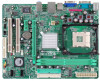
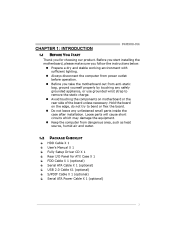
... of the board unless necessary. P4M900-M4 CHAPTER 1: INTRODUCTION 1.1 BEFORE YOU START Thank you take the motherboard out from dangerous area, such as heat source, humid air and water. 1.2 PACKAGE CHECKLIST HDD Cable X 1 User's Manual X 1 Fully Setup Driver CD X 1 Rear I/O Panel for choosing our product. Before you start installing the motherboard, please make sure you...
... of the board unless necessary. P4M900-M4 CHAPTER 1: INTRODUCTION 1.1 BEFORE YOU START Thank you take the motherboard out from dangerous area, such as heat source, humid air and water. 1.2 PACKAGE CHECKLIST HDD Cable X 1 User's Manual X 1 Fully Setup Driver CD X 1 Rear I/O Panel for choosing our product. Before you start installing the motherboard, please make sure you...
Setup Manual
Page 4
... GHz (Do not support Willamette CPU.) Supports Hyper Threading technology Supports Hyper Threading technology *It is recommended to use processors with 95W power consumption. Motherboard Manual 1.3 MOTHERBOARD FEATURES Ver 5.x Socket 478 Socket 478 Ver 6.x Intel Pent ium 4 / Celeron D processor up to Intel Pent ium 4 / Celeron D ..."Smart Guardian" function DIMM S lots x 2 Supports DDR2 533 / 667 95W power consumption. 400 / 533 / 800 MHz VIA P4M900 VIA VT8237A Chrome9 HC 3D / 2D Graphics Max Shared Video Memory is not supported Integrated IDE Controller IDE Ultra DMA 33~133 Bus Master...
... GHz (Do not support Willamette CPU.) Supports Hyper Threading technology Supports Hyper Threading technology *It is recommended to use processors with 95W power consumption. Motherboard Manual 1.3 MOTHERBOARD FEATURES Ver 5.x Socket 478 Socket 478 Ver 6.x Intel Pent ium 4 / Celeron D processor up to Intel Pent ium 4 / Celeron D ..."Smart Guardian" function DIMM S lots x 2 Supports DDR2 533 / 667 95W power consumption. 400 / 533 / 800 MHz VIA P4M900 VIA VT8237A Chrome9 HC 3D / 2D Graphics Max Shared Video Memory is not supported Integrated IDE Controller IDE Ultra DMA 33~133 Bus Master...
Setup Manual
Page 6
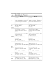
... represents the default setting. However, when connecting external microphone to the audio port, please use the Line In (blue) and Mic In (Pink) audio jack. 6 Motherboard Manual 1.4 REAR PANEL CONNECTORS (FOR VER 5.X) LAN AUDIO JACK PS/2 Mouse PS/2 Keyboard COM1 VGA USBX2 USBX2 Center Rear Side Line In Line Out Mic In...
... represents the default setting. However, when connecting external microphone to the audio port, please use the Line In (blue) and Mic In (Pink) audio jack. 6 Motherboard Manual 1.4 REAR PANEL CONNECTORS (FOR VER 5.X) LAN AUDIO JACK PS/2 Mouse PS/2 Keyboard COM1 VGA USBX2 USBX2 Center Rear Side Line In Line Out Mic In...
Setup Manual
Page 8
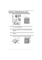
Step 3: Hold the CPU down firmly, and then close the lever to the JCFAN1. Step 4: Put the CPU Fan on the CPU and buckle it. The white dot/cut edge. Connect the CPU FAN power cable to complete the installation. The CPU will fit only in the correct orientation. Motherboard Manual CHAPTER 2: HARDWARE INSTALLATION 2.1 INSTALLING CENTRAL PROCESSING UNIT (CPU) Step 1: Pull the lever sideways away from the socket and then raise the lever up to a 90-degree angle. This completes the installation. 8 Step 2: Look for the white dot/cut edge should point wards the lever pivot.
Step 3: Hold the CPU down firmly, and then close the lever to the JCFAN1. Step 4: Put the CPU Fan on the CPU and buckle it. The white dot/cut edge. Connect the CPU FAN power cable to complete the installation. The CPU will fit only in the correct orientation. Motherboard Manual CHAPTER 2: HARDWARE INSTALLATION 2.1 INSTALLING CENTRAL PROCESSING UNIT (CPU) Step 1: Pull the lever sideways away from the socket and then raise the lever up to a 90-degree angle. This completes the installation. 8 Step 2: Look for the white dot/cut edge should point wards the lever pivot.

Setup Manual
Page 10
B. Unlock a DIMM slot by pressing the retaining clips outward. Align a DIMM on the slot such that the notch on the DIMM matches the break on the Slot. 2. Memory Capacity DIMM Socket Location DIMM1 DIMM2 DDR Module 256MB/512MB/1GB/2GB 256MB/512MB/1GB/2GB Total Memory Size Max is properly seated. Insert the DIMM vertically and firmly into the slot until the retaining chip snap back in place and the DIMM is 4GB. 10 DIMM1 DIMM2 Memory Modules 1. Motherboard Manual 2.3 INSTALLING SYSTEM MEMORY A.
B. Unlock a DIMM slot by pressing the retaining clips outward. Align a DIMM on the slot such that the notch on the DIMM matches the break on the Slot. 2. Memory Capacity DIMM Socket Location DIMM1 DIMM2 DDR Module 256MB/512MB/1GB/2GB 256MB/512MB/1GB/2GB Total Memory Size Max is properly seated. Insert the DIMM vertically and firmly into the slot until the retaining chip snap back in place and the DIMM is 4GB. 10 DIMM1 DIMM2 Memory Modules 1. Motherboard Manual 2.3 INSTALLING SYSTEM MEMORY A.

Setup Manual
Page 12
PCI-Express 1.0a compliant. PCI-EX1_1: PCI-Express x1 Slot - This PCI slot is equipped with 2 standard PCI slots. Motherboard Manual PCI-EX16: PCI-Express x16 Slot PCI-Express 1.0a compliant. Maximum theoretical realized bandwidth of 4GB/s simultaneously per direction; 500MB...data pins. 2X bandwidth over the traditional PCI architecture. PCI1 PCI2 12 PCI-EX16 PCI-EX1_1 PCI1~PCI2: Peripheral Component Interconnect Slots This motherboard is designated as 32 bits. Data transfer bandwidth up to 250MB/s per direction, for expansion cards. PCI-Express supports a raw bit-...
PCI-Express 1.0a compliant. PCI-EX1_1: PCI-Express x1 Slot - This PCI slot is equipped with 2 standard PCI slots. Motherboard Manual PCI-EX16: PCI-Express x16 Slot PCI-Express 1.0a compliant. Maximum theoretical realized bandwidth of 4GB/s simultaneously per direction; 500MB...data pins. 2X bandwidth over the traditional PCI architecture. PCI1 PCI2 12 PCI-EX16 PCI-EX1_1 PCI1~PCI2: Peripheral Component Interconnect Slots This motherboard is designated as 32 bits. Data transfer bandwidth up to 250MB/s per direction, for expansion cards. PCI-Express supports a raw bit-...
Setup Manual
Page 14
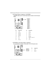
Motherboard Manual ATX Power Source Connector: JATXPWR1 JATXPWR1 allows user to connect 24-pin power connector on the ATX power supply. 12 24 1 13 Pin Assignment Pin Assignment 13 14 15 16 17 18 19 20 21 22 23 24 +3.3V -12V Ground PS_ON Ground Ground Ground NC +5V +5V +5V Ground 1 2 3 4 5 6 7 8 9 10 11 12 +3.3V +3.3V Ground +5V Ground +5V Ground PW_OK Standby Voltage+5V +12V +12V +3.3V JATXPWR2: ATX Power Source Connector By connecting this connector, it will provide +12V to CPU power circuit. 1 2 4 3 Pin 1 2 3 4 Assignment +12V +12V Ground Ground 14
Motherboard Manual ATX Power Source Connector: JATXPWR1 JATXPWR1 allows user to connect 24-pin power connector on the ATX power supply. 12 24 1 13 Pin Assignment Pin Assignment 13 14 15 16 17 18 19 20 21 22 23 24 +3.3V -12V Ground PS_ON Ground Ground Ground NC +5V +5V +5V Ground 1 2 3 4 5 6 7 8 9 10 11 12 +3.3V +3.3V Ground +5V Ground +5V Ground PW_OK Standby Voltage+5V +12V +12V +3.3V JATXPWR2: ATX Power Source Connector By connecting this connector, it will provide +12V to CPU power circuit. 1 2 4 3 Pin 1 2 3 4 Assignment +12V +12V Ground Ground 14

Setup Manual
Page 16
... Jack Sense 2 1 10 9 JCDIN1: CD-ROM Audio-in Connector This connector allows user to connect the front audio output cable with the PC front panel. Motherboard Manual JAUDIOF1: Front Panel Audio Header This header allows user to connect the audio source from the variaty devices, like CD-ROM, DVD-ROM, PCI sound...
... Jack Sense 2 1 10 9 JCDIN1: CD-ROM Audio-in Connector This connector allows user to connect the front audio output cable with the PC front panel. Motherboard Manual JAUDIOF1: Front Panel Audio Header This header allows user to connect the audio source from the variaty devices, like CD-ROM, DVD-ROM, PCI sound...
Setup Manual
Page 18
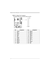
Motherboard Manual JPRNT1: Printer Port Connector This header allows you to connector printer on the PC. 25 2 1 Pin 1 2 3 4 5 6 7 8 9 10 11 12 13 Assignment -Strobe -ALF Data 0 -Error Data 1 -Init Data 2 -Scltin Data 3 Ground Data 4 Ground Data 5 Pin 14 15 16 17 18 19 20 21 22 23 24 25 26 Assignment Ground Data 6 Ground Data 7 Ground -ACK Ground Busy Ground PE Ground SCLT Key 18
Motherboard Manual JPRNT1: Printer Port Connector This header allows you to connector printer on the PC. 25 2 1 Pin 1 2 3 4 5 6 7 8 9 10 11 12 13 Assignment -Strobe -ALF Data 0 -Error Data 1 -Init Data 2 -Scltin Data 3 Ground Data 4 Ground Data 5 Pin 14 15 16 17 18 19 20 21 22 23 24 25 26 Assignment Ground Data 6 Ground Data 7 Ground -ACK Ground Busy Ground PE Ground SCLT Key 18
Setup Manual
Page 19
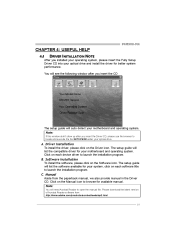
...manual, we also provide manual in the Driver CD. B. Click on each software title to launch the installation program. Note: You will need Acrobat Reader to browse for better system performance. P4M900-M4 CHAPTER 4: USEFUL HELP 4.1 DRIVER INSTALLATION NOTE After you insert the CD The setup guide will auto detect your motherboard...for your system, click on the Manual icon to open the manual file. A. Manual Aside from http://www.adobe.com/products/acrobat/readstep2.html 19 You will list the compatible driver for your motherboard and operating system. The setup guide...
...manual, we also provide manual in the Driver CD. B. Click on each software title to launch the installation program. Note: You will need Acrobat Reader to browse for better system performance. P4M900-M4 CHAPTER 4: USEFUL HELP 4.1 DRIVER INSTALLATION NOTE After you insert the CD The setup guide will auto detect your motherboard...for your system, click on the Manual icon to open the manual file. A. Manual Aside from http://www.adobe.com/products/acrobat/readstep2.html 19 You will list the compatible driver for your motherboard and operating system. The setup guide...
Setup Manual
Page 20
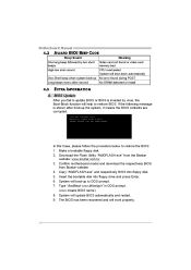
...Type "Awdflash xxxx.bf/sn/py/r" in DOS prompt. (xxxx means BIOS name.) 8. Download the Flash Utility "AWDFLASH.exe" from Biostar website. 4. System will work properly. 20 BIOS Update In this Case, please follow the procedure below to restore BIOS. Insert the ... floppy disk. 5. Make a bootable floppy disk. 2. Confirm motherboard model and download the respectively BIOS from the Biostar website: www.biostar.com.tw 3. The BIOS has been recovered and will update BIOS automatically and restart. 9. Motherboard Manual 4.2 AWARD BIOS BEEP CODE Beep Sound Meaning Video card not ...
...Type "Awdflash xxxx.bf/sn/py/r" in DOS prompt. (xxxx means BIOS name.) 8. Download the Flash Utility "AWDFLASH.exe" from Biostar website. 4. System will work properly. 20 BIOS Update In this Case, please follow the procedure below to restore BIOS. Insert the ... floppy disk. 5. Make a bootable floppy disk. 2. Confirm motherboard model and download the respectively BIOS from the Biostar website: www.biostar.com.tw 3. The BIOS has been recovered and will update BIOS automatically and restart. 9. Motherboard Manual 4.2 AWARD BIOS BEEP CODE Beep Sound Meaning Video card not ...

Setup Manual
Page 22
... important. Check cable running from disk to the system at any time. Backing up data and applications Hard disk can be read and applications files. Motherboard Manual 4.4 1. disk controller board. Back up the hard drive is Power light don't illuminate, fan securely plugged in setup. is in . Set master/slave jumpers second...
... important. Check cable running from disk to the system at any time. Backing up data and applications Hard disk can be read and applications files. Motherboard Manual 4.4 1. disk controller board. Back up the hard drive is Power light don't illuminate, fan securely plugged in setup. is in . Set master/slave jumpers second...
Setup Manual
Page 24
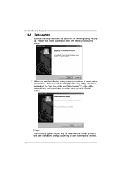
... and [WarpSpeeder™] utility will be automatically and immediately launched after you click "Finish" button. Usage: The following dialog in this user manual will pop up. Motherboard Manual 5.3 INSTALLATION 1. Please click "Next" button and follow the default procedure to your motherboard on hand. 24 If the "Launch the WarpSpeeder Tray Utility" checkbox is completed.
... and [WarpSpeeder™] utility will be automatically and immediately launched after you click "Finish" button. Usage: The following dialog in this user manual will pop up. Motherboard Manual 5.3 INSTALLATION 1. Please click "Next" button and follow the default procedure to your motherboard on hand. 24 If the "Launch the WarpSpeeder Tray Utility" checkbox is completed.
Setup Manual
Page 26
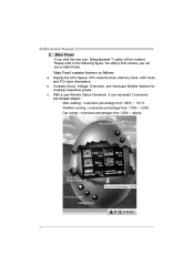
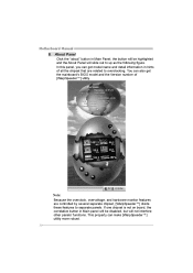
Motherboard Manual 2. the utility's first window you click the tray icon, [WarpSpeeder™] utility will see is Main Panel. c. Contains About, Voltage, Overclock, and Hardware Monitor Buttons ...
Motherboard Manual 2. the utility's first window you click the tray icon, [WarpSpeeder™] utility will see is Main Panel. c. Contains About, Voltage, Overclock, and Hardware Monitor Buttons ...
Setup Manual
Page 28
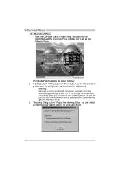
... you verify every speed you . "-3MHz button", "-1MHz button", "+1MHz button", and "+3MHz button": provide user the ability to do a fail-safe reboot. 28 b. Motherboard Manual 4. Warning: Manually overclock is potentially dangerous, especially when the overclocking percentage is over 110 %. Let user select a restoring way if system need to left as the following...
... you verify every speed you . "-3MHz button", "-1MHz button", "+1MHz button", and "+3MHz button": provide user the ability to do a fail-safe reboot. 28 b. Motherboard Manual 4. Warning: Manually overclock is potentially dangerous, especially when the overclocking percentage is over 110 %. Let user select a restoring way if system need to left as the following...
Setup Manual
Page 30
...;] divide these features to up as the following figure. If one chipset is not on board, the correlative button in hints of [WarpSpeeder™] utility. Motherboard Manual 6.
...;] divide these features to up as the following figure. If one chipset is not on board, the correlative button in hints of [WarpSpeeder™] utility. Motherboard Manual 6.
Setup Manual
Page 46
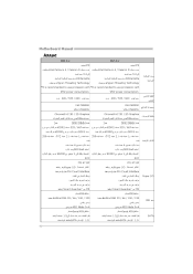
...Motherboard Manual ARABIC Ver 6.x 478 Intel Pentium 4 / Celeron D 3.4 Willamette Hyper-Threading Technology Ver 5.x 478 Intel Pentium 4 / Celeron D 3.4 Willamette Hyper-Threading Technology *It is recommended to use processors with *It is recommended to use processors with 95W power consumption 400 / 533 / 800 VIA P4M900... VIA VT8237A Chrome9 HC 3D / 2D Graphics 256 95W power consumption 400 / 533 / 800 VIA P4M900 VIA VT8237A Chrome9 HC 3D / 2D Graphics ...
...Motherboard Manual ARABIC Ver 6.x 478 Intel Pentium 4 / Celeron D 3.4 Willamette Hyper-Threading Technology Ver 5.x 478 Intel Pentium 4 / Celeron D 3.4 Willamette Hyper-Threading Technology *It is recommended to use processors with *It is recommended to use processors with 95W power consumption 400 / 533 / 800 VIA P4M900... VIA VT8237A Chrome9 HC 3D / 2D Graphics 256 95W power consumption 400 / 533 / 800 VIA P4M900 VIA VT8237A Chrome9 HC 3D / 2D Graphics ...
Setup Manual
Page 48
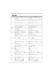
... VT8237A Chrome9 HC 3D / 2D Graphics 256MBです DDR2 DIMM x 2 DDR2 533 / 667 VIA P4M900 ト VIA VT8237A Chrome9 HC 3D / 2D Graphics 256MBです DDR2 DIMM x 2 DDR2 533 / 667 各DIMMは 256/512MB/1GB/2GB ...33 / 66 / 100 / 133 Ultra DMA 33 / 66 / 100 / 133 PIO Mode 0~4 ATA PIO Mode 0~4 ATA 1.5 Gb SATA 1.0 SATA 最高1.5 Gb SATA 1.0 48 Motherboard Manual JAPANESE Ver 5.x Socket 478 Socket 478 Ver 6.x Intel Pent ium 4 / Celeron D processor up to Intel Pent ium 4 / Celeron D processor up to 3.4 GHz (Willamette CPU CPU...
... VT8237A Chrome9 HC 3D / 2D Graphics 256MBです DDR2 DIMM x 2 DDR2 533 / 667 VIA P4M900 ト VIA VT8237A Chrome9 HC 3D / 2D Graphics 256MBです DDR2 DIMM x 2 DDR2 533 / 667 各DIMMは 256/512MB/1GB/2GB ...33 / 66 / 100 / 133 Ultra DMA 33 / 66 / 100 / 133 PIO Mode 0~4 ATA PIO Mode 0~4 ATA 1.5 Gb SATA 1.0 SATA 最高1.5 Gb SATA 1.0 48 Motherboard Manual JAPANESE Ver 5.x Socket 478 Socket 478 Ver 6.x Intel Pent ium 4 / Celeron D processor up to Intel Pent ium 4 / Celeron D processor up to 3.4 GHz (Willamette CPU CPU...
Bios Setup
Page 2
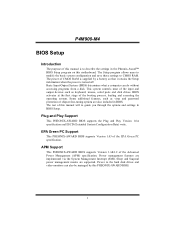
... power management modes are implemented via the System Management Interrupt (SMI). APM Support This PHEONIX-AWARD BIOS supports Version 1.1&1.2 of this manual will to describe the settings in the Pheonix-Award™ BIOS Setup program on this PHEONIX-AWARD BIOS. 1 Power management features... 1.0A specification and ESCD (Extended System Configuration Data) write. Power to CMOS RAM. P4M900-M4 BIOS Setup Introduction The purpose of this manual is turned off. The power of CMOS RAM is supplied by this motherboard. The rest of the Advanced Power Management (APM) specification.
... power management modes are implemented via the System Management Interrupt (SMI). APM Support This PHEONIX-AWARD BIOS supports Version 1.1&1.2 of this manual will to describe the settings in the Pheonix-Award™ BIOS Setup program on this PHEONIX-AWARD BIOS. 1 Power management features... 1.0A specification and ESCD (Extended System Configuration Data) write. Power to CMOS RAM. P4M900-M4 BIOS Setup Introduction The purpose of this manual is turned off. The power of CMOS RAM is supplied by this motherboard. The rest of the Advanced Power Management (APM) specification.


