
Setup Manual
Page 3
P4M900-M7 SE/P4M890-M7 TE CHAPTER 1: INTRODUCTION 1.1 BEFORE YOU START Thank you take the motherboard out from dangerous area, such as heat source, humid air and water. 1.2 PACKAGE CHECKLIST HDD Cable X 1 Installation Guide X 1 Fully Setup Driver CD X 1 (full version manual files inside the case after installation. Hold the board on motherboard or the rear side of the...
P4M900-M7 SE/P4M890-M7 TE CHAPTER 1: INTRODUCTION 1.1 BEFORE YOU START Thank you take the motherboard out from dangerous area, such as heat source, humid air and water. 1.2 PACKAGE CHECKLIST HDD Cable X 1 Installation Guide X 1 Fully Setup Driver CD X 1 (full version manual files inside the case after installation. Hold the board on motherboard or the rear side of the...

Setup Manual
Page 4
... and ECC DIMM is not Registered DIMM and ECC DIMM is 64 MB ITE 8712F Provides the most commonly used legacy Super I /O functionality. Motherboard Manual 1.3 MOTHERBOARD FEATURES CPU FSB P4M900-M7 SE P4M890-M7 TE LGA 775 LGA 775 Intel Core2Duo/ Pentium 4 / Pentium D / Intel Core2Duo/ Pentium 4 / Pentium D / Celeron D / Celeron 4xx ... consumption. 95W power consumption. 533 / 800 / 1066 MHz 533 / 800 / 1066 MHz Chipset VIA P4M900 VIA VT8237A VIA P4M890 VIA VT8237A Graphic Chrome9 HC 3D / 2D Graphics Max Shared Video Memory is 256 MB Unichrome Pro IGP Max Shared Video Memory...
... and ECC DIMM is not Registered DIMM and ECC DIMM is 64 MB ITE 8712F Provides the most commonly used legacy Super I /O functionality. Motherboard Manual 1.3 MOTHERBOARD FEATURES CPU FSB P4M900-M7 SE P4M890-M7 TE LGA 775 LGA 775 Intel Core2Duo/ Pentium 4 / Pentium D / Intel Core2Duo/ Pentium 4 / Pentium D / Celeron D / Celeron 4xx ... consumption. 95W power consumption. 533 / 800 / 1066 MHz 533 / 800 / 1066 MHz Chipset VIA P4M900 VIA VT8237A VIA P4M890 VIA VT8237A Graphic Chrome9 HC 3D / 2D Graphics Max Shared Video Memory is 256 MB Unichrome Pro IGP Max Shared Video Memory...

Setup Manual
Page 6
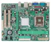
Motherboard Manual 1.5 MOTHERBOARD LAYOUT JKBMS1 LGA775 JCFAN1 COJMC1OM1 CPU1 JATXPWR1 JVGA1 DIMM1 DIMM2 JPRNT1 JUSB1 JUSBLAN1 JATXPWR2 JAUDIO1 LAN P4M900 or P4M890 PCI-EX16 Super I/O BAT1 PCI-EX1_1 JCDIN1 Codec JAUDIOF1 PCI1 PCI2 BIOS JUSB2 JUSB3 FDD1 Note: ■ rep resen ts th e 1 st pin. 6 VIA VT8237A JSATA2 JSATA1 JCMOS1 JPANEL1 JSFAN1 IDE1 IDE2
Motherboard Manual 1.5 MOTHERBOARD LAYOUT JKBMS1 LGA775 JCFAN1 COJMC1OM1 CPU1 JATXPWR1 JVGA1 DIMM1 DIMM2 JPRNT1 JUSB1 JUSBLAN1 JATXPWR2 JAUDIO1 LAN P4M900 or P4M890 PCI-EX16 Super I/O BAT1 PCI-EX1_1 JCDIN1 Codec JAUDIOF1 PCI1 PCI2 BIOS JUSB2 JUSB3 FDD1 Note: ■ rep resen ts th e 1 st pin. 6 VIA VT8237A JSATA2 JSATA1 JCMOS1 JPANEL1 JSFAN1 IDE1 IDE2

Setup Manual
Page 8
The CPU will fit only in the correct orientation. Connect the CPU FAN power cable into the JCFAN1. Motherboard Manual Step 2: Look for the triangular cut edge on socket, and the golden dot on the retention frame. Step 4: Put the CPU Fan and heatsink assembly on the CPU and buckle it on CPU should point forwards this triangular cut edge. Step 2-1: Step 2-2: Step 3: Hold the CPU down firmly, and then lower the lever to locked position to complete the installation. This completes the installation. 8
The CPU will fit only in the correct orientation. Connect the CPU FAN power cable into the JCFAN1. Motherboard Manual Step 2: Look for the triangular cut edge on socket, and the golden dot on the retention frame. Step 4: Put the CPU Fan and heatsink assembly on the CPU and buckle it on CPU should point forwards this triangular cut edge. Step 2-1: Step 2-2: Step 3: Hold the CPU down firmly, and then lower the lever to locked position to complete the installation. This completes the installation. 8

Setup Manual
Page 10
Insert the DIMM vertically and firmly into the slot until the retaining chip snap back in place and the DIMM is 4GB. 10 Motherboard Manual 2.3 INSTALLING SYSTEM MEMORY A. B. Align a DIMM on the slot such that the notch on the DIMM matches the break on the Slot. 2. Memory Capacity DIMM Socket Location DDR Module DIMM1 256MB/512MB/1GB/2GB DIMM2 256MB/512MB/1GB/2GB Total Memory Size Max is properly seated. Memory Modules DIMM1 DIMM2 1. Unlock a DIMM slot by pressing the retaining clips outward.
Insert the DIMM vertically and firmly into the slot until the retaining chip snap back in place and the DIMM is 4GB. 10 Motherboard Manual 2.3 INSTALLING SYSTEM MEMORY A. B. Align a DIMM on the slot such that the notch on the DIMM matches the break on the Slot. 2. Memory Capacity DIMM Socket Location DDR Module DIMM1 256MB/512MB/1GB/2GB DIMM2 256MB/512MB/1GB/2GB Total Memory Size Max is properly seated. Memory Modules DIMM1 DIMM2 1. Unlock a DIMM slot by pressing the retaining clips outward.

Setup Manual
Page 12
... for Peripheral Component Interconnect, and it is a bus standard for an aggregate of 2.5Gb/s on the data pins. - 2X bandwidth over the traditional PCI architecture. Motherboard Manual PCI-EX16: PCI-Express x16 Slot - PCI-EX16 PCI-EX1_1 PCI1/PCI2: Peripheral Component Interconnect Slots This...
... for Peripheral Component Interconnect, and it is a bus standard for an aggregate of 2.5Gb/s on the data pins. - 2X bandwidth over the traditional PCI architecture. Motherboard Manual PCI-EX16: PCI-Express x16 Slot - PCI-EX16 PCI-EX1_1 PCI1/PCI2: Peripheral Component Interconnect Slots This...

Setup Manual
Page 14
Pin Assignment 1 4 1 +12V 2 +12V 2 3 3 Ground 4 Ground 14 Motherboard Manual ATX Power Source Connector: JATXPWR1 JATXPWR1 allows user to connect 24-pin power connector on the ATX power supply. 12 24 Pin Assignment 13 +3.3V ...
Pin Assignment 1 4 1 +12V 2 +12V 2 3 3 Ground 4 Ground 14 Motherboard Manual ATX Power Source Connector: JATXPWR1 JATXPWR1 allows user to connect 24-pin power connector on the ATX power supply. 12 24 Pin Assignment 13 +3.3V ...

Setup Manual
Page 16
Motherboard Manual JCDIN1: CD-ROM Audio-in Connector This connector allows user to "Pin 2-3 close ". 5. Remove AC power line. 2. Wait for five seconds. 4. Set the jumper to ... to restore the BIOS safe setting and the CMOS data, please carefully follow the procedures to "Pin 1-2 close ". 3. Set the jumper to avoid damaging the motherboard. 13 Pin 1-2 Close: Normal Operation (default). 13 13 Pin 2-3 Close: Clear CMOS data. ※ Clear CMOS Procedures: 1. Pin Assignment 1 Left Channel Input 2 Ground 3 Ground 4 Right...
Motherboard Manual JCDIN1: CD-ROM Audio-in Connector This connector allows user to "Pin 2-3 close ". 5. Remove AC power line. 2. Wait for five seconds. 4. Set the jumper to ... to restore the BIOS safe setting and the CMOS data, please carefully follow the procedures to "Pin 1-2 close ". 3. Set the jumper to avoid damaging the motherboard. 13 Pin 1-2 Close: Normal Operation (default). 13 13 Pin 2-3 Close: Clear CMOS data. ※ Clear CMOS Procedures: 1. Pin Assignment 1 Left Channel Input 2 Ground 3 Ground 4 Right...

Setup Manual
Page 18
... 0 defines a disk striping scheme that does not require fault tolerance. Benefits: provides increased data throughput, especially for large files. Depending on the system environment. Motherboard Manual CHAPTER 4: RAID FUNCTIONS 4.1 OPERATION SYSTEM Supports Windows XP Home/Professional Edition, and Windows 2000 Professional. 4.2 RAID ARRAYS RAID supports the following types of the...
... 0 defines a disk striping scheme that does not require fault tolerance. Benefits: provides increased data throughput, especially for large files. Depending on the system environment. Motherboard Manual CHAPTER 4: RAID FUNCTIONS 4.1 OPERATION SYSTEM Supports Windows XP Home/Professional Edition, and Windows 2000 Professional. 4.2 RAID ARRAYS RAID supports the following types of the...

Setup Manual
Page 20
...The setup guide will list the compatible driver for available manual. Driver Installation To install the driver, please click on each software title to launch the installation program. Note: You will auto detect your motherboard and operating system. Please download the latest version of ...You will see the following window after you insert the Driver CD, please use file browser to browse for your optical drive. Motherboard Manual CHAPTER 5: USEFUL HELP 5.1 DRIVER INSTALLATION NOTE After you installed your operating system, please insert the Fully Setup Driver CD into your...
...The setup guide will list the compatible driver for available manual. Driver Installation To install the driver, please click on each software title to launch the installation program. Note: You will auto detect your motherboard and operating system. Please download the latest version of ...You will see the following window after you insert the Driver CD, please use file browser to browse for your optical drive. Motherboard Manual CHAPTER 5: USEFUL HELP 5.1 DRIVER INSTALLATION NOTE After you installed your operating system, please insert the Fully Setup Driver CD into your...

Setup Manual
Page 22
... applications can be used but booting from hard disk 2. Cannot boot system after installing second hard drive. 1. Re-install applications and data using backup disks. Motherboard Manual 5.4 TROUBLESHOOTING Probable Solution 1. Keyboard lights are on . Call the drive manufacturers for compatibility with other drives. 22 Make sure both ends of breaking down firmly...
... applications can be used but booting from hard disk 2. Cannot boot system after installing second hard drive. 1. Re-install applications and data using backup disks. Motherboard Manual 5.4 TROUBLESHOOTING Probable Solution 1. Keyboard lights are on . Call the drive manufacturers for compatibility with other drives. 22 Make sure both ends of breaking down firmly...

Setup Manual
Page 24
Motherboard Manual 6.3 INSTALLATION 1. When you see the following dialog will change according to install. 2. Please click "Next" button and follow the default procedure to your motherboard on hand. 24 Usage: The following figures are only for reference, the screen printed in setup procedure, it means setup is completed. Click "Finish" button. Execute the setup execution file, and then the following dialog in this user manual will pop up.
Motherboard Manual 6.3 INSTALLATION 1. When you see the following dialog will change according to install. 2. Please click "Next" button and follow the default procedure to your motherboard on hand. 24 Usage: The following figures are only for reference, the screen printed in setup procedure, it means setup is completed. Click "Finish" button. Execute the setup execution file, and then the following dialog in this user manual will pop up.
Setup Manual
Page 26
As you can see, the Overclock Panel is on the right side, and the Overvoltage Panel is on the left side. 26 Motherboard Manual 3. Overclock/Overvoltage Panel Click the Overclock/Overvoltage button in the Main Panel, the button will be highlighted and the Overclock/Overvoltage Panel will show up as the following figure.
As you can see, the Overclock Panel is on the right side, and the Overvoltage Panel is on the left side. 26 Motherboard Manual 3. Overclock/Overvoltage Panel Click the Overclock/Overvoltage button in the Main Panel, the button will be highlighted and the Overclock/Overvoltage Panel will show up as the following figure.

Setup Manual
Page 28
... voltage. b. "Memory Voltage": This function allows user to adjust CPU voltage. In this panel, you can get the real-time status information of your system. Motherboard Manual Overvoltage Panel contains these features: a. Hardware Monitor Panel Click the Hardware Monitor button in Main Panel, the button will show up as the following figure...
... voltage. b. "Memory Voltage": This function allows user to adjust CPU voltage. In this panel, you can get the real-time status information of your system. Motherboard Manual Overvoltage Panel contains these features: a. Hardware Monitor Panel Click the Hardware Monitor button in Main Panel, the button will show up as the following figure...

Setup Manual
Page 46
Motherboard Manual JAPANESE P4M900-M7 SE P4M890-M7 TE CPU LGA 775 LGA 775 Intel Core2Duo/ Pentium 4 / Pentium D / Intel Core2Duo/ Pentium 4 / Pentium D / Celeron D / Celeron 4xx processor up to 3.8 Celeron D / Celeron 4xx processor up to 3.8 ... to use processors with 95W power consumption. 95W power consumption. FSB 533 / 800 / 1066 MHz 533 / 800 / 1066 MHz VIA P4M900 ト VIA VT8237A VIA P4M890 VIA VT8237A Chrome9 HC 3D / 2D Graphics クス 256MBです Unichrome Pro IGP 64MBです DDR2 DIMM x 2 DDR2 DIMM x 2 DDR2 533 / 667...
Motherboard Manual JAPANESE P4M900-M7 SE P4M890-M7 TE CPU LGA 775 LGA 775 Intel Core2Duo/ Pentium 4 / Pentium D / Intel Core2Duo/ Pentium 4 / Pentium D / Celeron D / Celeron 4xx processor up to 3.8 Celeron D / Celeron 4xx processor up to 3.8 ... to use processors with 95W power consumption. 95W power consumption. FSB 533 / 800 / 1066 MHz 533 / 800 / 1066 MHz VIA P4M900 ト VIA VT8237A VIA P4M890 VIA VT8237A Chrome9 HC 3D / 2D Graphics クス 256MBです Unichrome Pro IGP 64MBです DDR2 DIMM x 2 DDR2 DIMM x 2 DDR2 533 / 667...
Bios Setup
Page 2
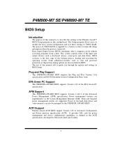
...and save these settings to guide you through the options and settings in the Phoenix-Award™ BIOS Setup program on this motherboard. The rest of this manual will to CMOS RAM. Some additional features, such as virus and password protection or chipset fine-tuning options are implemented via ... Setup information when the power is to the hard disk drives and video monitors can do without accessing programs from a disk. P4M900-M7 SE/P4M890-M7 TE BIOS Setup Introduction The purpose of this manual is turned off. BIOS activates at the first stage of the EPA Green PC specification.
...and save these settings to guide you through the options and settings in the Phoenix-Award™ BIOS Setup program on this motherboard. The rest of this manual will to CMOS RAM. Some additional features, such as virus and password protection or chipset fine-tuning options are implemented via ... Setup information when the power is to the hard disk drives and video monitors can do without accessing programs from a disk. P4M900-M7 SE/P4M890-M7 TE BIOS Setup Introduction The purpose of this manual is turned off. BIOS activates at the first stage of the EPA Green PC specification.


