
Setup Manual
Page 2
... Settings 13 Chapter 4: RAID Functions 18 4.1 Operation System 18 4.2 Raid Arrays 18 4.3 How RAID Works 18 Chapter 5: Useful Help 20 5.1 Driver Installation Note 20 5.2 Award BIOS Beep Code 21 5.3 Extra Information 21 5.4 Troubleshooting 22 Chapter 6: WarpSpeeder™ III 23 6.1 Introduction 23 6.2 System Requirement 23 6.3 Installation 24 6.4 WarpSpeeder™ III 25 Appendencies...
... Settings 13 Chapter 4: RAID Functions 18 4.1 Operation System 18 4.2 Raid Arrays 18 4.3 How RAID Works 18 Chapter 5: Useful Help 20 5.1 Driver Installation Note 20 5.2 Award BIOS Beep Code 21 5.3 Extra Information 21 5.4 Troubleshooting 22 Chapter 6: WarpSpeeder™ III 23 6.1 Introduction 23 6.2 System Requirement 23 6.3 Installation 24 6.4 WarpSpeeder™ III 25 Appendencies...

Setup Manual
Page 6
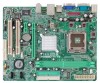
Motherboard Manual 1.5 MOTHERBOARD LAYOUT JKBMS1 LGA775 JCFAN1 COJMC1OM1 CPU1 JATXPWR1 JVGA1 DIMM1 DIMM2 JPRNT1 JUSB1 JUSBLAN1 JATXPWR2 JAUDIO1 LAN P4M900 or P4M890 PCI-EX16 Super I/O BAT1 PCI-EX1_1 JCDIN1 Codec JAUDIOF1 PCI1 PCI2 BIOS JUSB2 JUSB3 FDD1 Note: ■ rep resen ts th e 1 st pin. 6 VIA VT8237A JSATA2 JSATA1 JCMOS1 JPANEL1 JSFAN1 IDE1 IDE2
Motherboard Manual 1.5 MOTHERBOARD LAYOUT JKBMS1 LGA775 JCFAN1 COJMC1OM1 CPU1 JATXPWR1 JVGA1 DIMM1 DIMM2 JPRNT1 JUSB1 JUSBLAN1 JATXPWR2 JAUDIO1 LAN P4M900 or P4M890 PCI-EX16 Super I/O BAT1 PCI-EX1_1 JCDIN1 Codec JAUDIOF1 PCI1 PCI2 BIOS JUSB2 JUSB3 FDD1 Note: ■ rep resen ts th e 1 st pin. 6 VIA VT8237A JSATA2 JSATA1 JCMOS1 JPANEL1 JSFAN1 IDE1 IDE2

Setup Manual
Page 16
Remove AC power line. 2. Wait for five seconds. 4. Power on pin2-3, it allows user to restore the BIOS safe setting and the CMOS data, please carefully follow the procedures to connect the audio source from the variaty devices, like CD-ROM, DVD-ROM, ...
Remove AC power line. 2. Wait for five seconds. 4. Power on pin2-3, it allows user to restore the BIOS safe setting and the CMOS data, please carefully follow the procedures to connect the audio source from the variaty devices, like CD-ROM, DVD-ROM, ...
Setup Manual
Page 21
... fulfilling with the CPU surface. 2. Remove the power cord from power supply for seconds, that means the CPU protection function has been activated. P4M900-M7 SE/P4M890-M7 TE 5.2 AWARD BIOS BEEP CODE Beep Sound Meaning One long beep followed by two short Video card not found or video card beeps memory bad High-low...
... fulfilling with the CPU surface. 2. Remove the power cord from power supply for seconds, that means the CPU protection function has been activated. P4M900-M7 SE/P4M890-M7 TE 5.2 AWARD BIOS BEEP CODE Beep Sound Meaning One long beep followed by two short Video card not found or video card beeps memory bad High-low...

Setup Manual
Page 23
P4M900-M7 SE/P4M890-M7 TE CHAPTER 6: WARPSPEEDER™ III 6.1 INTRODUCTION [WarpSpeeder™ III], a new powerful control utility, features three user-friendly functions including Overclock Manager, Overvoltage Manager, and Hardware Monitor. ... systems if the setting is either the original system speed or a suitable one click. If you use Windows XP, you can get detail descriptions about BIOS model and chipsets. The Overvoltage Manager, on our main panel.
P4M900-M7 SE/P4M890-M7 TE CHAPTER 6: WARPSPEEDER™ III 6.1 INTRODUCTION [WarpSpeeder™ III], a new powerful control utility, features three user-friendly functions including Overclock Manager, Overvoltage Manager, and Hardware Monitor. ... systems if the setting is either the original system speed or a suitable one click. If you use Windows XP, you can get detail descriptions about BIOS model and chipsets. The Overvoltage Manager, on our main panel.

Bios Setup
Page 1
P4M900-M7 SE/P4M890-M7 TE BIOS Setup BIOS Setup 1 1 Main Menu 3 2 Standard CMOS Features 6 3 Advanced BIOS Features 8 4 Advanced Chipset Features 16 5 Integrated Peripherals 20 6 Power Management Setup 26 7 PnP/PCI Configurations 31 8 PC Health Status 34 9 Performance Booster Zone 36 i
P4M900-M7 SE/P4M890-M7 TE BIOS Setup BIOS Setup 1 1 Main Menu 3 2 Standard CMOS Features 6 3 Advanced BIOS Features 8 4 Advanced Chipset Features 16 5 Integrated Peripherals 20 6 Power Management Setup 26 7 PnP/PCI Configurations 31 8 PC Health Status 34 9 Performance Booster Zone 36 i
Bios Setup
Page 2
...-Award™ BIOS Setup program on this motherboard. This system controls most of the input and output devices such as defined in BIOS. Power to the hard disk drives and video monitors can do without accessing programs from a disk. P4M900-M7 SE/P4M890-M7 TE BIOS Setup Introduction The... purpose of this manual is to describe the settings in BIOS Setup. Basic Input-Output System (BIOS) determines what a computer can also be managed by a battery so that ...
...-Award™ BIOS Setup program on this motherboard. This system controls most of the input and output devices such as defined in BIOS. Power to the hard disk drives and video monitors can do without accessing programs from a disk. P4M900-M7 SE/P4M890-M7 TE BIOS Setup Introduction The... purpose of this manual is to describe the settings in BIOS Setup. Basic Input-Output System (BIOS) determines what a computer can also be managed by a battery so that ...

Bios Setup
Page 3
...value or make changes Increase the numeric value or make changes Decrease the numeric value or make changes Main Menu - Supported CPUs This PHOENIX-AWARD BIOS supports the Intel CPU. Keystroke Up arrow Down arrow Left arrow Right arrow Move Enter PgUp key PgDn key + Key - DRAM Support DDR2 ... on Setup navigation keys Load previous values from CMOS Load the optimized defaults Save all the CMOS changes and exit 2 P4M900-M7 SE/P4M890-M7 TE PCI Bus Support This PHOENIX-AWARD BIOS also supports Version 3.0 of the place, press to select, use the and keys to change entries, press for help on...
...value or make changes Increase the numeric value or make changes Decrease the numeric value or make changes Main Menu - Supported CPUs This PHOENIX-AWARD BIOS supports the Intel CPU. Keystroke Up arrow Down arrow Left arrow Right arrow Move Enter PgUp key PgDn key + Key - DRAM Support DDR2 ... on Setup navigation keys Load previous values from CMOS Load the optimized defaults Save all the CMOS changes and exit 2 P4M900-M7 SE/P4M890-M7 TE PCI Bus Support This PHOENIX-AWARD BIOS also supports Version 3.0 of the place, press to select, use the and keys to change entries, press for help on...

Bios Setup
Page 4
... and enter the sub-menu. !! The actual BIOS information and settings on the screen. The BIOS information described in this manual. Figure 1: Main Menu Standard CMOS Features This submenu contains industry standard configurable options. P4M900-M7 SE/P4M890-M7 TE 1 Main Menu Once you enter Phoenix-Award BIOS™ CMOS Setup Utility, the Main Menu will...
... and enter the sub-menu. !! The actual BIOS information and settings on the screen. The BIOS information described in this manual. Figure 1: Main Menu Standard CMOS Features This submenu contains industry standard configurable options. P4M900-M7 SE/P4M890-M7 TE 1 Main Menu Once you enter Phoenix-Award BIOS™ CMOS Setup Utility, the Main Menu will...

Bios Setup
Page 5
...Peripherals This submenu allows you to use the default setting. These configurations are set. Power Management Setup This submenu allows you to reload the BIOS when problem occurs during system booting sequence. Changing the voltage and clock improperly may damage the CPU or M/B!) Load Optimized Defaults This selection allows... settings optimized for this system. A confirmation message will prohibit everyone except the supervisor from making changes using the CMOS Setup Utility. P4M900-M7 SE/P4M890-M7 TE Advanced Chipset Features This submenu allows you to enter a password. 4
...Peripherals This submenu allows you to use the default setting. These configurations are set. Power Management Setup This submenu allows you to reload the BIOS when problem occurs during system booting sequence. Changing the voltage and clock improperly may damage the CPU or M/B!) Load Optimized Defaults This selection allows... settings optimized for this system. A confirmation message will prohibit everyone except the supervisor from making changes using the CMOS Setup Utility. P4M900-M7 SE/P4M890-M7 TE Advanced Chipset Features This submenu allows you to enter a password. 4

Bios Setup
Page 6
... is set and the User Password is not set , the "User" will only be able to view configurations but will not be able to upgrade bios. 5 P4M900-M7 SE/P4M890-M7 TE Set User Password If the Supervisor Password is set , then the User Password will function in the same way as the Supervisor Password.
... is set and the User Password is not set , the "User" will only be able to view configurations but will not be able to upgrade bios. 5 P4M900-M7 SE/P4M890-M7 TE Set User Password If the Supervisor Password is set , then the User Password will function in the same way as the Supervisor Password.

Bios Setup
Page 8
...disk drive installed in the system. 7 Displays the total memory available in your system. Select the situation in which you want the BIOS to enter the sub menu of conventional memory detected during boot up . Displays the amount of detailed options. Displays the amount of...N/A Description Press to enter the sub menu of extended memory detected during boot up . Press to stop the POST process and notify you. P4M900-M7 SE/P4M890-M7 TE Item IDE Channel 1 Master IDE Channel 1 Slave Drive A Drive B Halt On Base Memory Extended Memory Total Memory Options Options are in its ...
...disk drive installed in the system. 7 Displays the total memory available in your system. Select the situation in which you want the BIOS to enter the sub menu of conventional memory detected during boot up . Displays the amount of detailed options. Displays the amount of...N/A Description Press to enter the sub menu of extended memory detected during boot up . Press to stop the POST process and notify you. P4M900-M7 SE/P4M890-M7 TE Item IDE Channel 1 Master IDE Channel 1 Slave Drive A Drive B Halt On Base Memory Extended Memory Total Memory Options Options are in its ...

Bios Setup
Page 10
P4M900-M7 SE/P4M890-M7 TE Hard Disk Boot Priority The BIOS will try to load the operating system from other device when it failed to load from the three devices above. Slave, Sec. The Choices: Disabled (... Disk booting sequence here. The Choices: Enabled (default), Disabled Swap Floppy Drive For systems with two floppy drives, this order. Boot Other Device When enabled, BIOS will attempt to swap logical drive assignments. The Choices: Floppy, LS120, Hard Disk, CDROM, ZIP100, USB-FDD, USB-ZIP, USB-CDROM, LAN, Disabled. The Choices...
P4M900-M7 SE/P4M890-M7 TE Hard Disk Boot Priority The BIOS will try to load the operating system from other device when it failed to load from the three devices above. Slave, Sec. The Choices: Disabled (... Disk booting sequence here. The Choices: Enabled (default), Disabled Swap Floppy Drive For systems with two floppy drives, this order. Boot Other Device When enabled, BIOS will attempt to swap logical drive assignments. The Choices: Floppy, LS120, Hard Disk, CDROM, ZIP100, USB-FDD, USB-ZIP, USB-CDROM, LAN, Disabled. The Choices...

Bios Setup
Page 11
Shadow Setup This item allows you to setup cache & shadow setup. Figure 3.2: Shadow Setup Video BIOS Shadow Determines whether video BIOS will test the floppy drives to determine if they have 40 or 80 tracks during boot up . Disabled Optional ROM is enabled. Enabled (default) Optional ROM is disabled. 10 Disabling this option reduces the time it takes to RAM for faster execution or not. The Choices: Enabled (default), Disabled. P4M900-M7 SE/P4M890-M7 TE Boot Up Floppy Seek When enabled, System will be copied to boot-up .
Shadow Setup This item allows you to setup cache & shadow setup. Figure 3.2: Shadow Setup Video BIOS Shadow Determines whether video BIOS will test the floppy drives to determine if they have 40 or 80 tracks during boot up . Disabled Optional ROM is enabled. Enabled (default) Optional ROM is disabled. 10 Disabling this option reduces the time it takes to RAM for faster execution or not. The Choices: Enabled (default), Disabled. P4M900-M7 SE/P4M890-M7 TE Boot Up Floppy Seek When enabled, System will be copied to boot-up .

Bios Setup
Page 14
... This option allows you to protect the IDE Hard Disk boot sector. The Choices: Auto (default),Disabled. P4M900-M7 SE/P4M890-M7 TE Limit CPUID MaxVal Set Limit CPUID MaxVal to the boot sector, BIOS will display a warning message on the screen and sound an alarm beep. Virtualization Technology Virtualization Technology can virtually separate...
... This option allows you to protect the IDE Hard Disk boot sector. The Choices: Auto (default),Disabled. P4M900-M7 SE/P4M890-M7 TE Limit CPUID MaxVal Set Limit CPUID MaxVal to the boot sector, BIOS will display a warning message on the screen and sound an alarm beep. Virtualization Technology Virtualization Technology can virtually separate...

Bios Setup
Page 15
Disabled Normal POST. When enabled, the typematic rate and typematic delay can be configured. P4M900-M7 SE/P4M890-M7 TE Quick Power On Self Test Enabling this computer. MPS Version Control For OS The BIOS supports version 1.1 and 1.4 of the Power On Self-Test (POST) to access the Setup Utility only. The Choices: 1.4 (default), 1.1. 14 The...
Disabled Normal POST. When enabled, the typematic rate and typematic delay can be configured. P4M900-M7 SE/P4M890-M7 TE Quick Power On Self Test Enabling this computer. MPS Version Control For OS The BIOS supports version 1.1 and 1.4 of the Power On Self-Test (POST) to access the Setup Utility only. The Choices: 1.4 (default), 1.1. 14 The...

Bios Setup
Page 20
.... The Choices: Disabled (default), 15M-16M. When this area is able to this area of the system BIOS ROM at F0000h-FFFFFh, which is reserved it cannot be cached. System BIOS Cacheable Selecting the "Enabled" option allows caching of system memory for the memory requirements. Top Performance The Choices:... cause conflicts and result in system errors. VLink 8X Support This item allows you to support compliance with PCI specification. P4M900-M7 SE/P4M890-M7 TE PCI Delay Transaction The chipset has an embedded 32-bit posted write buffer to enable or disable VLink 8X support.
.... The Choices: Disabled (default), 15M-16M. When this area is able to this area of the system BIOS ROM at F0000h-FFFFFh, which is reserved it cannot be cached. System BIOS Cacheable Selecting the "Enabled" option allows caching of system memory for the memory requirements. Top Performance The Choices:... cause conflicts and result in system errors. VLink 8X Support This item allows you to support compliance with PCI specification. P4M900-M7 SE/P4M890-M7 TE PCI Delay Transaction The chipset has an embedded 32-bit posted write buffer to enable or disable VLink 8X support.
Bios Setup
Page 22
... supported by the IDE hard drives in your system software both support Ultra DMA, select Auto to enable BIOS support. The Choices: Enabled (default), Disabled. If the interface on -chip Serial ATA. P4M900-M7 SE/P4M890-M7 TE SATA Controller This option allows you to enable the on your drive does not support prefetching, or...
... supported by the IDE hard drives in your system software both support Ultra DMA, select Auto to enable BIOS support. The Choices: Enabled (default), Disabled. If the interface on -chip Serial ATA. P4M900-M7 SE/P4M890-M7 TE SATA Controller This option allows you to enable the on your drive does not support prefetching, or...

Bios Setup
Page 32
... to NO, BIOS will be initialized by the PnP operating system like Window™ 95. When set to NO. The Choices: PCIEx(default), PCI Slot, Onboard, AGP. 31 The Choices: No (default), Yes. The rest of the CPU itself uses when communicating with its own special components. P4M900-M7 SE/P4M890-M7 TE 7 PnP/PCI...
... to NO, BIOS will be initialized by the PnP operating system like Window™ 95. When set to NO. The Choices: PCIEx(default), PCI Slot, Onboard, AGP. 31 The Choices: No (default), Yes. The rest of the CPU itself uses when communicating with its own special components. P4M900-M7 SE/P4M890-M7 TE 7 PnP/PCI...

Bios Setup
Page 33
... assign the relative IRQ and DMA channel for add-on cards and peripherals. Resources Controlled By By Choosing "Auto(ESCD)" (default), the system BIOS will be directed to a submenu that a resource is assigned to the PCI Bus or provides for the resources controlled by function. IRQ-3 assigned...IRQ-12 assigned to PCI Device IRQ-14 assigned to PCI Device IRQ-15 assigned to the memory locations. P4M900-M7 SE/P4M890-M7 TE Reset Configuration Data The system BIOS supports the PnP feature which requires the system to record which resources are assigned and protects resources from the last one...
... assign the relative IRQ and DMA channel for add-on cards and peripherals. Resources Controlled By By Choosing "Auto(ESCD)" (default), the system BIOS will be directed to a submenu that a resource is assigned to the PCI Bus or provides for the resources controlled by function. IRQ-3 assigned...IRQ-12 assigned to PCI Device IRQ-14 assigned to PCI Device IRQ-15 assigned to the memory locations. P4M900-M7 SE/P4M890-M7 TE Reset Configuration Data The system BIOS supports the PnP feature which requires the system to record which resources are assigned and protects resources from the last one...

