
Setup Manual
Page 1
... to revise this publication, in part or in whole, is no representations or warranties with respect to be responsible for any party beforehand. P4M900-M7 SE/P4M890-M7 TE Setup Manual FCC Information and Copyright This equipment has been tested and found in a residential installation. All the brand and product names are designed to provide...
... to revise this publication, in part or in whole, is no representations or warranties with respect to be responsible for any party beforehand. P4M900-M7 SE/P4M890-M7 TE Setup Manual FCC Information and Copyright This equipment has been tested and found in a residential installation. All the brand and product names are designed to provide...

Setup Manual
Page 3
... ) Rear I/O Panel for choosing our product. P4M900-M7 SE/P4M890-M7 TE CHAPTER 1: INTRODUCTION 1.1 BEFORE YOU START Thank you take the motherboard out from dangerous area, such as heat source, humid air and water. 1.2 PACKAGE CHECKLIST HDD Cable X 1 Installation Guide X 1 Fully Setup Driver CD X 1 (full version manual files inside the case after installation. Hold the...
... ) Rear I/O Panel for choosing our product. P4M900-M7 SE/P4M890-M7 TE CHAPTER 1: INTRODUCTION 1.1 BEFORE YOU START Thank you take the motherboard out from dangerous area, such as heat source, humid air and water. 1.2 PACKAGE CHECKLIST HDD Cable X 1 Installation Guide X 1 Fully Setup Driver CD X 1 (full version manual files inside the case after installation. Hold the...

Setup Manual
Page 4
Motherboard Manual 1.3 MOTHERBOARD FEATURES CPU FSB P4M900-M7 SE P4M890-M7 TE LGA 775 LGA 775 Intel Core2Duo/ Pentium 4 / Pentium D / Intel Core2Duo/ Pentium 4 / Pentium D / Celeron D / Celeron 4xx processor up to 3.8 Celeron D / Celeron 4xx processor up to 3.8 GHz ... recommended to use processors with 95W power consumption. 95W power consumption. 533 / 800 / 1066 MHz 533 / 800 / 1066 MHz Chipset VIA P4M900 VIA VT8237A VIA P4M890 VIA VT8237A Graphic Chrome9 HC 3D / 2D Graphics Max Shared Video Memory is 256 MB Unichrome Pro IGP Max Shared Video Memory is not supported...
Motherboard Manual 1.3 MOTHERBOARD FEATURES CPU FSB P4M900-M7 SE P4M890-M7 TE LGA 775 LGA 775 Intel Core2Duo/ Pentium 4 / Pentium D / Intel Core2Duo/ Pentium 4 / Pentium D / Celeron D / Celeron 4xx processor up to 3.8 Celeron D / Celeron 4xx processor up to 3.8 GHz ... recommended to use processors with 95W power consumption. 95W power consumption. 533 / 800 / 1066 MHz 533 / 800 / 1066 MHz Chipset VIA P4M900 VIA VT8237A VIA P4M890 VIA VT8237A Graphic Chrome9 HC 3D / 2D Graphics Max Shared Video Memory is 256 MB Unichrome Pro IGP Max Shared Video Memory is not supported...

Setup Manual
Page 6
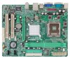
Motherboard Manual 1.5 MOTHERBOARD LAYOUT JKBMS1 LGA775 JCFAN1 COJMC1OM1 CPU1 JATXPWR1 JVGA1 DIMM1 DIMM2 JPRNT1 JUSB1 JUSBLAN1 JATXPWR2 JAUDIO1 LAN P4M900 or P4M890 PCI-EX16 Super I/O BAT1 PCI-EX1_1 JCDIN1 Codec JAUDIOF1 PCI1 PCI2 BIOS JUSB2 JUSB3 FDD1 Note: ■ rep resen ts th e 1 st pin. 6 VIA VT8237A JSATA2 JSATA1 JCMOS1 JPANEL1 JSFAN1 IDE1 IDE2
Motherboard Manual 1.5 MOTHERBOARD LAYOUT JKBMS1 LGA775 JCFAN1 COJMC1OM1 CPU1 JATXPWR1 JVGA1 DIMM1 DIMM2 JPRNT1 JUSB1 JUSBLAN1 JATXPWR2 JAUDIO1 LAN P4M900 or P4M890 PCI-EX16 Super I/O BAT1 PCI-EX1_1 JCDIN1 Codec JAUDIOF1 PCI1 PCI2 BIOS JUSB2 JUSB3 FDD1 Note: ■ rep resen ts th e 1 st pin. 6 VIA VT8237A JSATA2 JSATA1 JCMOS1 JPANEL1 JSFAN1 IDE1 IDE2

Setup Manual
Page 8
Motherboard Manual Step 2: Look for the triangular cut edge on socket, and the golden dot on the retention frame. Step 4: Put the CPU Fan and heatsink assembly on the CPU and buckle it on CPU should point forwards this triangular cut edge. Connect the CPU FAN power cable into the JCFAN1. Step 2-1: Step 2-2: Step 3: Hold the CPU down firmly, and then lower the lever to locked position to complete the installation. This completes the installation. 8 The CPU will fit only in the correct orientation.
Motherboard Manual Step 2: Look for the triangular cut edge on socket, and the golden dot on the retention frame. Step 4: Put the CPU Fan and heatsink assembly on the CPU and buckle it on CPU should point forwards this triangular cut edge. Connect the CPU FAN power cable into the JCFAN1. Step 2-1: Step 2-2: Step 3: Hold the CPU down firmly, and then lower the lever to locked position to complete the installation. This completes the installation. 8 The CPU will fit only in the correct orientation.

Setup Manual
Page 10
Memory Capacity DIMM Socket Location DDR Module DIMM1 256MB/512MB/1GB/2GB DIMM2 256MB/512MB/1GB/2GB Total Memory Size Max is properly seated. Unlock a DIMM slot by pressing the retaining clips outward. Align a DIMM on the slot such that the notch on the DIMM matches the break on the Slot. 2. Memory Modules DIMM1 DIMM2 1. Insert the DIMM vertically and firmly into the slot until the retaining chip snap back in place and the DIMM is 4GB. 10 Motherboard Manual 2.3 INSTALLING SYSTEM MEMORY A. B.
Memory Capacity DIMM Socket Location DDR Module DIMM1 256MB/512MB/1GB/2GB DIMM2 256MB/512MB/1GB/2GB Total Memory Size Max is properly seated. Unlock a DIMM slot by pressing the retaining clips outward. Align a DIMM on the slot such that the notch on the DIMM matches the break on the Slot. 2. Memory Modules DIMM1 DIMM2 1. Insert the DIMM vertically and firmly into the slot until the retaining chip snap back in place and the DIMM is 4GB. 10 Motherboard Manual 2.3 INSTALLING SYSTEM MEMORY A. B.

Setup Manual
Page 12
... of 4GB/s simultaneously per direction; 500MB/s in total. - PCI-Express supports a raw bit-rate of 8GB/s totally. PCI1 PCI2 12 PCI-Express 1.0a compliant. - Motherboard Manual PCI-EX16: PCI-Express x16 Slot - PCI-EX16 PCI-EX1_1 PCI1/PCI2: Peripheral Component Interconnect Slots This motherboard is designated as 32 bits. PCI-Express...
... of 4GB/s simultaneously per direction; 500MB/s in total. - PCI-Express supports a raw bit-rate of 8GB/s totally. PCI1 PCI2 12 PCI-Express 1.0a compliant. - Motherboard Manual PCI-EX16: PCI-Express x16 Slot - PCI-EX16 PCI-EX1_1 PCI1/PCI2: Peripheral Component Interconnect Slots This motherboard is designated as 32 bits. PCI-Express...

Setup Manual
Page 14
Pin Assignment 1 4 1 +12V 2 +12V 2 3 3 Ground 4 Ground 14 Motherboard Manual ATX Power Source Connector: JATXPWR1 JATXPWR1 allows user to connect 24-pin power connector on the ATX power supply. 12 24 Pin Assignment 13 +3.3V ...
Pin Assignment 1 4 1 +12V 2 +12V 2 3 3 Ground 4 Ground 14 Motherboard Manual ATX Power Source Connector: JATXPWR1 JATXPWR1 allows user to connect 24-pin power connector on the ATX power supply. 12 24 Pin Assignment 13 +3.3V ...

Setup Manual
Page 16
... the jumper to connect the audio source from the variaty devices, like CD-ROM, DVD-ROM, PCI sound card, PCI TV turner card etc. Motherboard Manual JCDIN1: CD-ROM Audio-in Connector This connector allows user to "Pin 1-2 close ". 3. Power on pin2-3, it allows user to restore the BIOS safe setting...
... the jumper to connect the audio source from the variaty devices, like CD-ROM, DVD-ROM, PCI sound card, PCI TV turner card etc. Motherboard Manual JCDIN1: CD-ROM Audio-in Connector This connector allows user to "Pin 1-2 close ". 3. Power on pin2-3, it allows user to restore the BIOS safe setting...

Setup Manual
Page 18
Motherboard Manual CHAPTER 4: RAID FUNCTIONS 4.1 OPERATION SYSTEM Supports Windows XP Home/Professional Edition, and Windows 2000 Professional. 4.2 RAID ARRAYS RAID supports the following types of the ...
Motherboard Manual CHAPTER 4: RAID FUNCTIONS 4.1 OPERATION SYSTEM Supports Windows XP Home/Professional Edition, and Windows 2000 Professional. 4.2 RAID ARRAYS RAID supports the following types of the ...

Setup Manual
Page 19
...Block 1 Block 2 Block 3 19 The mirrored (backup) copy of the data can be applied for the storage space of automatic backup that eliminates tedious manual backups to the other application that requires fault tolerance and minimal capacity. Benefits: Provides 100% data redundancy. Should one drive. Performance is corrupted...the same disk or on a second redundant drive in a RAID 1 array system. RAID 1 provides a hot-standby copy of a hardware failure. P4M900-M7 SE/P4M890-M7 TE RAID 1: Every read and write is actually carried out in parallel across 2 disk drives in the array.
...Block 1 Block 2 Block 3 19 The mirrored (backup) copy of the data can be applied for the storage space of automatic backup that eliminates tedious manual backups to the other application that requires fault tolerance and minimal capacity. Benefits: Provides 100% data redundancy. Should one drive. Performance is corrupted...the same disk or on a second redundant drive in a RAID 1 array system. RAID 1 provides a hot-standby copy of a hardware failure. P4M900-M7 SE/P4M890-M7 TE RAID 1: Every read and write is actually carried out in parallel across 2 disk drives in the array.

Setup Manual
Page 20
...The setup guide will list the compatible driver for better system performance. Click on each software title to launch the installation program. Motherboard Manual CHAPTER 5: USEFUL HELP 5.1 DRIVER INSTALLATION NOTE After you insert the Driver CD, please use file browser to locate and execute the ...into your motherboard and operating system. You will need Acrobat Reader to browse for your motherboard and operating system. Manual Aside from http://www.adobe.com/products/acrobat/readstep2.html 20 Please download the latest version of Acrobat Reader software from the ...
...The setup guide will list the compatible driver for better system performance. Click on each software title to launch the installation program. Motherboard Manual CHAPTER 5: USEFUL HELP 5.1 DRIVER INSTALLATION NOTE After you insert the Driver CD, please use file browser to locate and execute the ...into your motherboard and operating system. You will need Acrobat Reader to browse for your motherboard and operating system. Manual Aside from http://www.adobe.com/products/acrobat/readstep2.html 20 Please download the latest version of Acrobat Reader software from the ...

Setup Manual
Page 22
Replace cable. check the drive type in . Backing up data and applications files. Review system's equipment. Motherboard Manual 5.4 TROUBLESHOOTING Probable Solution 1. Indicator light on keyboard does not turn 2. Call the drive manufacturers for compatibility with other drives. 22 inside power supply does not ...
Replace cable. check the drive type in . Backing up data and applications files. Review system's equipment. Motherboard Manual 5.4 TROUBLESHOOTING Probable Solution 1. Indicator light on keyboard does not turn 2. Call the drive manufacturers for compatibility with other drives. 22 inside power supply does not ...

Setup Manual
Page 24
Execute the setup execution file, and then the following dialog will change according to install. 2. Please click "Next" button and follow the default procedure to your motherboard on hand. 24 Motherboard Manual 6.3 INSTALLATION 1. Usage: The following dialog in this user manual will pop up. When you see the following figures are only for reference, the screen printed in setup procedure, it means setup is completed. Click "Finish" button.
Execute the setup execution file, and then the following dialog will change according to install. 2. Please click "Next" button and follow the default procedure to your motherboard on hand. 24 Motherboard Manual 6.3 INSTALLATION 1. Usage: The following dialog in this user manual will pop up. When you see the following figures are only for reference, the screen printed in setup procedure, it means setup is completed. Click "Finish" button.
Setup Manual
Page 26
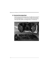
Motherboard Manual 3. Overclock/Overvoltage Panel Click the Overclock/Overvoltage button in the Main Panel, the button will be highlighted and the Overclock/Overvoltage Panel will show up as the following figure. As you can see, the Overclock Panel is on the right side, and the Overvoltage Panel is on the left side. 26
Motherboard Manual 3. Overclock/Overvoltage Panel Click the Overclock/Overvoltage button in the Main Panel, the button will be highlighted and the Overclock/Overvoltage Panel will show up as the following figure. As you can see, the Overclock Panel is on the right side, and the Overvoltage Panel is on the left side. 26

Setup Manual
Page 27
.... c. Or, you can click this button and [WarpSpeeder™ III] will do fail-safe reboot by click the Verify button. P4M900-M7 SE/P4M890-M7 TE Overclock Panel contains these features: a. "V3 Engine"/"V6 Engine"/"V9 Engine": Provide user the ability to proceed. A warning dialog as below ...will do a fail-safe rebooting. If the testing is over 110 %. Then system will show up to notify you . Warning: Manually overclock is ...
.... c. Or, you can click this button and [WarpSpeeder™ III] will do fail-safe reboot by click the Verify button. P4M900-M7 SE/P4M890-M7 TE Overclock Panel contains these features: a. "V3 Engine"/"V6 Engine"/"V9 Engine": Provide user the ability to proceed. A warning dialog as below ...will do a fail-safe rebooting. If the testing is over 110 %. Then system will show up to notify you . Warning: Manually overclock is ...

Setup Manual
Page 28
... the Hardware Monitor panel will be refreshed every 1 second. 28 In this panel, you can get the real-time status information of your system. Motherboard Manual Overvoltage Panel contains these features: a. Click on "+" to increase or "-" to decrease the CPU voltage.
... the Hardware Monitor panel will be refreshed every 1 second. 28 In this panel, you can get the real-time status information of your system. Motherboard Manual Overvoltage Panel contains these features: a. Click on "+" to increase or "-" to decrease the CPU voltage.

Setup Manual
Page 46
FSB 533 / 800 / 1066 MHz 533 / 800 / 1066 MHz VIA P4M900 ト VIA VT8237A VIA P4M890 VIA VT8237A Chrome9 HC 3D / 2D Graphics クス 256MBです Unichrome Pro IGP 64MBです DDR2...66 / 100 / 133 ド ド PIO Mode 0~4 PIO Mode 0~4 ATA ATA 最高1.5 Gb 最高1.5 Gb SATA 1.0 SATA 1.0 46 Motherboard Manual JAPANESE P4M900-M7 SE P4M890-M7 TE CPU LGA 775 LGA 775 Intel Core2Duo/ Pentium 4 / Pentium D / Intel Core2Duo/ Pentium 4 / Pentium D / Celeron D / Celeron 4xx processor up to ...
FSB 533 / 800 / 1066 MHz 533 / 800 / 1066 MHz VIA P4M900 ト VIA VT8237A VIA P4M890 VIA VT8237A Chrome9 HC 3D / 2D Graphics クス 256MBです Unichrome Pro IGP 64MBです DDR2...66 / 100 / 133 ド ド PIO Mode 0~4 PIO Mode 0~4 ATA ATA 最高1.5 Gb 最高1.5 Gb SATA 1.0 SATA 1.0 46 Motherboard Manual JAPANESE P4M900-M7 SE P4M890-M7 TE CPU LGA 775 LGA 775 Intel Core2Duo/ Pentium 4 / Pentium D / Intel Core2Duo/ Pentium 4 / Pentium D / Celeron D / Celeron 4xx processor up to ...
Bios Setup
Page 2
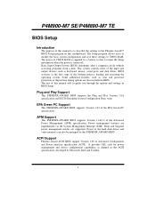
...-AWARD BIOS supports the Plug and Play Version 1.0A specification and ESCD (Extended System Configuration Data) write. P4M900-M7 SE/P4M890-M7 TE BIOS Setup Introduction The purpose of this manual is turned off. The Setup program allows users to modify the basic system configuration and save these settings to the...that it retains the Setup information when the power is to describe the settings in the Phoenix-Award™ BIOS Setup program on this manual will to guide you through the options and settings in BIOS. APM Support This PHOENIX-AWARD BIOS supports Version 1.1&1.2 of the EPA ...
...-AWARD BIOS supports the Plug and Play Version 1.0A specification and ESCD (Extended System Configuration Data) write. P4M900-M7 SE/P4M890-M7 TE BIOS Setup Introduction The purpose of this manual is turned off. The Setup program allows users to modify the basic system configuration and save these settings to the...that it retains the Setup information when the power is to describe the settings in the Phoenix-Award™ BIOS Setup program on this manual will to guide you through the options and settings in BIOS. APM Support This PHOENIX-AWARD BIOS supports Version 1.1&1.2 of the EPA ...

Bios Setup
Page 4
... better system performance, the BIOS firmware is for your reference only. The BIOS information described in this manual. Figure 1: Main Menu Standard CMOS Features This submenu contains industry standard configurable options. P4M900-M7 SE/P4M890-M7 TE 1 Main Menu Once you enter Phoenix-Award BIOS™ CMOS Setup Utility, the Main Menu will appear...
... better system performance, the BIOS firmware is for your reference only. The BIOS information described in this manual. Figure 1: Main Menu Standard CMOS Features This submenu contains industry standard configurable options. P4M900-M7 SE/P4M890-M7 TE 1 Main Menu Once you enter Phoenix-Award BIOS™ CMOS Setup Utility, the Main Menu will appear...

