
Setup Manual
Page 2
... 1: Introduction 1 1.1 Before You Start 1 1.2 Package Checklist 1 1.3 Motherboard Features 2 1.4 Rear Panel Connectors 3 1.5 Motherboard Layout 4 Chapter 2: Hardware Installation 5 2.1 Installing Central Processing Unit (CPU 5 2.2 FAN Headers 7 2.3 Installing System Memory 8 2.4 Connectors and Slots 10 Chapter 3: Headers & Jumpers Setup 14 3.1 How to Setup Jumpers 14 3.2 Detail Settings 14 Chapter 4: RAID Functions 19 4.1 Operation System 19 4.2 Raid...
... 1: Introduction 1 1.1 Before You Start 1 1.2 Package Checklist 1 1.3 Motherboard Features 2 1.4 Rear Panel Connectors 3 1.5 Motherboard Layout 4 Chapter 2: Hardware Installation 5 2.1 Installing Central Processing Unit (CPU 5 2.2 FAN Headers 7 2.3 Installing System Memory 8 2.4 Connectors and Slots 10 Chapter 3: Headers & Jumpers Setup 14 3.1 How to Setup Jumpers 14 3.2 Detail Settings 14 Chapter 4: RAID Functions 19 4.1 Operation System 19 4.2 Raid...
Setup Manual
Page 4
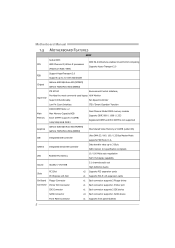
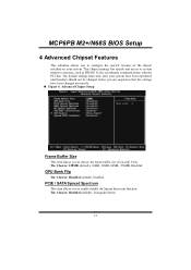
... Supports Hyper Transport 2.0 (Maximum Watt: 95W) Support HyperTransport 2.0 FSB Supports up to 2.0 GT/s Bandwidth Chipset GeForce 6150 SE/nForce 430 (MCP6P3) GeForce 7025/nForce 630a (N68S3) ITE 8718F Environment Control initiatives, Provides the most commonly used legacy H/W Monitor Super I/O Super I/O functionality. ... 800 / 1066 / 1333 Registered DIMM and ECC DIMM is not supported Graphics GeForce 6150 SE/nForce 430 (MCP6P3) GeForce 7025/nForce 630a (N68S3) Max Shared Video Memory is 512MB (under OS) IDE Integrated IDE Controller Ultra DMA 33 / 66 / 100 / 133 Bus Master...
... Supports Hyper Transport 2.0 (Maximum Watt: 95W) Support HyperTransport 2.0 FSB Supports up to 2.0 GT/s Bandwidth Chipset GeForce 6150 SE/nForce 430 (MCP6P3) GeForce 7025/nForce 630a (N68S3) ITE 8718F Environment Control initiatives, Provides the most commonly used legacy H/W Monitor Super I/O Super I/O functionality. ... 800 / 1066 / 1333 Registered DIMM and ECC DIMM is not supported Graphics GeForce 6150 SE/nForce 430 (MCP6P3) GeForce 7025/nForce 630a (N68S3) Max Shared Video Memory is 512MB (under OS) IDE Integrated IDE Controller Ultra DMA 33 / 66 / 100 / 133 Bus Master...

Setup Manual
Page 10
D D R3 _A 1 D D R3 _B 1 Motherboard Manual 2.3 INSTALLING SYSTEM MEMORY A. Unlock a DIMM slot by pressing the retaining clips outward. Insert the DIMM vertically and firmly into the slot until the retaining chip snap back in place and the DIMM is properly seated. 8 Align a DIMM on the slot such that the notch on the DIMM matches the break on the Slot. 2. Memory Modules 1.
D D R3 _A 1 D D R3 _B 1 Motherboard Manual 2.3 INSTALLING SYSTEM MEMORY A. Unlock a DIMM slot by pressing the retaining clips outward. Insert the DIMM vertically and firmly into the slot until the retaining chip snap back in place and the DIMM is properly seated. 8 Align a DIMM on the slot such that the notch on the DIMM matches the break on the Slot. 2. Memory Modules 1.
Setup Manual
Page 11
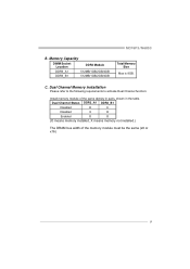
MCP6P3/N68S3 B. C. Memory Capacity DIMM Socket Location DDR3 Module DDR3_A1 512MB/1GB/2GB/4GB DDR3_B1 512MB/1GB/2GB/4GB Total Memory Size Max is 8GB. Dual Channel Status DDR3_A1 DDR3_B1 Disabled O X Disabled X O Enabled O O (O means memory installed, X means memory not installed.) The DRAM bus width of the same density in pairs, shown in the table. Dual Channel Memory installation Please refer to the following requirements to activate Dual Channel function: Install memory module of the memory module must be the same (x8 or x16) 9
MCP6P3/N68S3 B. C. Memory Capacity DIMM Socket Location DDR3 Module DDR3_A1 512MB/1GB/2GB/4GB DDR3_B1 512MB/1GB/2GB/4GB Total Memory Size Max is 8GB. Dual Channel Status DDR3_A1 DDR3_B1 Disabled O X Disabled X O Enabled O O (O means memory installed, X means memory not installed.) The DRAM bus width of the same density in pairs, shown in the table. Dual Channel Memory installation Please refer to the following requirements to activate Dual Channel function: Install memory module of the memory module must be the same (x8 or x16) 9
Setup Manual
Page 26
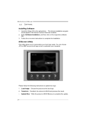
... computer. Transform:Transform the picture for BIOS and preview the result. 3. Motherboard Manual 5.2 SOFTWARE Installing Software 1. Update Bios:Write the picture to BIOS Memory to the optical drive. Please follow the following instructions to complete the installation. The drivers installation program would appear if the Autorun function has been...
... computer. Transform:Transform the picture for BIOS and preview the result. 3. Motherboard Manual 5.2 SOFTWARE Installing Software 1. Update Bios:Write the picture to BIOS Memory to the optical drive. Please follow the following instructions to complete the installation. The drivers installation program would appear if the Autorun function has been...
Setup Manual
Page 27
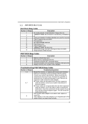
...the add-in card. Consult your system manufacturer's technical support. Remove all other expansion 6, 7 cards are absent, consult your system manufacturer. MCP6P3/N68S3 5.3 AMI BIOS BEEP CODE Boot Block Beep Codes Number of Beeps Description 1 No media present. (Insert diskette in floppy drive A:) ...does not match image present in flash device) POST BIOS Beep Codes Number of Beeps Description 1 Memory refresh timer error 3 Base memory read/write test error 6 Keyboard controller BAT command failed 7 General exception error (processor exception interrupt error) 8 Display...
...the add-in card. Consult your system manufacturer's technical support. Remove all other expansion 6, 7 cards are absent, consult your system manufacturer. MCP6P3/N68S3 5.3 AMI BIOS BEEP CODE Boot Block Beep Codes Number of Beeps Description 1 No media present. (Insert diskette in floppy drive A:) ...does not match image present in flash device) POST BIOS Beep Codes Number of Beeps Description 1 Memory refresh timer error 3 Base memory read/write test error 6 Keyboard controller BAT command failed 7 General exception error (processor exception interrupt error) 8 Display...

Bios Setup
Page 6
Upgrade BIOS This submenu allows you to CMOS (memory) and exit setup. Confirmation message will be displayed before proceeding. Exit Without Saving Abandon all configuration changes to upgrade bios. 6 Confirmation message will be displayed ...
Upgrade BIOS This submenu allows you to CMOS (memory) and exit setup. Confirmation message will be displayed before proceeding. Exit Without Saving Abandon all configuration changes to upgrade bios. 6 Confirmation message will be displayed ...
Bios Setup
Page 8
Displays the amount of floppy disk drive installed in your system. MCP6PB M2+/N68S BIOS Setup Item Drive A Video Halt On Base Memory Extended Memory Total Memory Options 360K, 5.25 in 1.2M, 5.25 in 720K, 3.5 in 1.44M, 3.5 in 2.88M, 3.5 in None EGA/ VG A CGA 40 CGA 80 MONO ... All, But Disk/ Key N/A N/A N/A Description Select the type of extended memory detected during boot up . Displays the amount of conventional memory detected during boot up . Select the situation in the system. 8 Displays the total memory available in which you want the BIOS to stop the POST process and notify...
Displays the amount of floppy disk drive installed in your system. MCP6PB M2+/N68S BIOS Setup Item Drive A Video Halt On Base Memory Extended Memory Total Memory Options 360K, 5.25 in 1.2M, 5.25 in 720K, 3.5 in 1.44M, 3.5 in 2.88M, 3.5 in None EGA/ VG A CGA 40 CGA 80 MONO ... All, But Disk/ Key N/A N/A N/A Description Select the type of extended memory detected during boot up . Displays the amount of conventional memory detected during boot up . Select the situation in the system. 8 Displays the total memory available in which you want the BIOS to stop the POST process and notify...
Bios Setup
Page 10
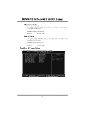
Disab led Disable cache. MCP6PB M2+/N68S BIOS Setup CPU Internal Cache Depending on the CPU, which may be able to setup boot sequence & Floppy. 10 External Cache This option enables or disables "Level 2" secondary cache on the CPU/chipset in use, you to increase memory access time with this option. Enabled (default) Enable cache. Boot Seq & Floppy Setup This item allows you may improve performance. Disab led Disable cache. Enabled (default) Enable cache.
Disab led Disable cache. MCP6PB M2+/N68S BIOS Setup CPU Internal Cache Depending on the CPU, which may be able to setup boot sequence & Floppy. 10 External Cache This option enables or disables "Level 2" secondary cache on the CPU/chipset in use, you to increase memory access time with this option. Enabled (default) Enable cache. Boot Seq & Floppy Setup This item allows you may improve performance. Disab led Disable cache. Enabled (default) Enable cache.
Bios Setup
Page 14
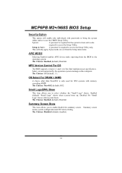
.../disable the summary screen. Small Logo(EPA) Show This item allows you to select whether the "Small Logo" shows. This will enable only individuals with memory exceeding 64MB. MCP6PB M2+/N68S BIOS Setup Security Option This option will only apply if passwords are set from the BIOS to use the CMOS...
.../disable the summary screen. Small Logo(EPA) Show This item allows you to select whether the "Small Logo" shows. This will enable only individuals with memory exceeding 64MB. MCP6PB M2+/N68S BIOS Setup Security Option This option will only apply if passwords are set from the BIOS to use the CMOS...
Bios Setup
Page 15
The default settings that came with the PCI bus. PCIE / SATA Spread Spectrum This item allows you to system memory resources, such as DRAM. This chipset manage bus speeds and access to enable/disable the Spread Spectrum function. The Choices: 128MB (default), 16MB, 32MB, 64MB, ...
The default settings that came with the PCI bus. PCIE / SATA Spread Spectrum This item allows you to system memory resources, such as DRAM. This chipset manage bus speeds and access to enable/disable the Spread Spectrum function. The Choices: 128MB (default), 16MB, 32MB, 64MB, ...
Bios Setup
Page 17
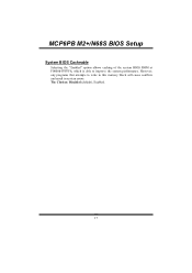
The Choices: Disabled (default), Enabled. 17 MCP6PB M2+/N68S BIOS Setup System BIOS Cacheable Selecting the "Enabled" option allows caching of the system BIOS ROM at F0000h-FFFFFh, which is able to this memory block will cause conflicts and result in system errors. However, any programs that attempts to write to improve the system performance.
The Choices: Disabled (default), Enabled. 17 MCP6PB M2+/N68S BIOS Setup System BIOS Cacheable Selecting the "Enabled" option allows caching of the system BIOS ROM at F0000h-FFFFFh, which is able to this memory block will cause conflicts and result in system errors. However, any programs that attempts to write to improve the system performance.
Bios Setup
Page 30
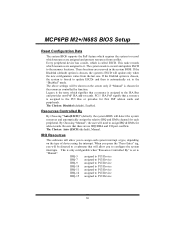
... PCI Device IRQ-10 assigned to PCI Device IRQ-11 assigned to PCI Device IRQ-14 assigned to PCI Device IRQ-15 assigned to the memory locations. If the Disabled (default) option is assigned to the PCI Bus or provides for the resources controlled by function. The Choices: Auto (ESCD) (default...
... PCI Device IRQ-10 assigned to PCI Device IRQ-11 assigned to PCI Device IRQ-14 assigned to PCI Device IRQ-15 assigned to the memory locations. If the Disabled (default) option is assigned to the PCI Bus or provides for the resources controlled by function. The Choices: Auto (ESCD) (default...
Bios Setup
Page 36
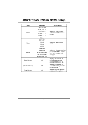
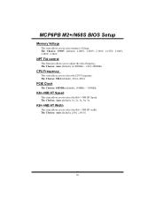
....0. The Choices: Auto (default), 1x, 2x, 3x, 4x, 5x. The Choices: Auto (default), x4 800Mhz ~ x24.5 4900Mhz CPU Frequency This item allows you to select memory Voltage. MCP6PB M2+/N68S BIOS Setup Memory Voltage This item allows you to adjust the ratio frequency.
....0. The Choices: Auto (default), 1x, 2x, 3x, 4x, 5x. The Choices: Auto (default), x4 800Mhz ~ x24.5 4900Mhz CPU Frequency This item allows you to select memory Voltage. MCP6PB M2+/N68S BIOS Setup Memory Voltage This item allows you to adjust the ratio frequency.

Bios Setup
Page 37
... Setup DRAM Configuration Timing Mode The Choices: Auto (default), MaxMemClk, Manual. The Choices: Unganged (default), Ganged. Memclock tri-stating The Choices: Disabled (default), Enabled. 37 Memory Clock value or Limit The Choices: DDR 400 (default), DDR 533, DDR 667, DDR 800. CKE base power down mode The Choices: Enabled (default), Disabled...
... Setup DRAM Configuration Timing Mode The Choices: Auto (default), MaxMemClk, Manual. The Choices: Unganged (default), Ganged. Memclock tri-stating The Choices: Disabled (default), Enabled. 37 Memory Clock value or Limit The Choices: DDR 400 (default), DDR 533, DDR 667, DDR 800. CKE base power down mode The Choices: Enabled (default), Disabled...
Bios Setup
Page 38
.... Trfc1 for DIMM0 The Choices: 75ns (default), 105ns, 127.5ns, 195ns, 327.5ns. Precharge Time The Choices: 3 clocks (default), 2 clocks. MCP6PB M2+/N68S BIOS Setup Memory Hole Remapping The Choices: Enabled (default), Disabled. Row Cycle Time The Choices: 26 bus clocks (default), 11-25 bus clocks. RAS to RAS Delay The...
.... Trfc1 for DIMM0 The Choices: 75ns (default), 105ns, 127.5ns, 195ns, 327.5ns. Precharge Time The Choices: 3 clocks (default), 2 clocks. MCP6PB M2+/N68S BIOS Setup Memory Hole Remapping The Choices: Enabled (default), Disabled. Row Cycle Time The Choices: 26 bus clocks (default), 11-25 bus clocks. RAS to RAS Delay The...


