Setup Manual
Page 3
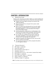
...optional) Serial ATA Cable X 2 Rear I/O Panel for choosing our product. Before you take the motherboard out from anti-static bag, ground yourself properly by touching any unfastened small parts inside ) FDD ...do not try to area or your motherboard version. 1 Loose parts will cause short circuits which may be 0 to remove the...working environment with sufficient lighting. Hold the board on motherboard or the rear side of the computer should be...humid air and water. CHAPTER 1: INTRODUCTION MCP6P3/N68S3 1.1 BEFORE YOU START Thank you for ATX Case X 1 Installation Guide X 1...
...optional) Serial ATA Cable X 2 Rear I/O Panel for choosing our product. Before you take the motherboard out from anti-static bag, ground yourself properly by touching any unfastened small parts inside ) FDD ...do not try to area or your motherboard version. 1 Loose parts will cause short circuits which may be 0 to remove the...working environment with sufficient lighting. Hold the board on motherboard or the rear side of the computer should be...humid air and water. CHAPTER 1: INTRODUCTION MCP6P3/N68S3 1.1 BEFORE YOU START Thank you for ATX Case X 1 Installation Guide X 1...
Setup Manual
Page 4
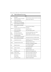
...Each connector supports 1 SATA device Front Panel Connector x1 Supports front panel facilities 2 SATA Version 2.0 specification compliant. Motherboard Manual 1.3 MOTHERBOARD FEATURES SPEC Socket AM3 AMD 64 Architecture enables 32 and 64 bit computing CPU AMD Phenom II/ Athlon II processors ... 2.0 (Maximum Watt: 95W) Support HyperTransport 2.0 FSB Supports up to 2.0 GT/s Bandwidth Chipset GeForce 6150 SE/nForce 430 (MCP6P3) GeForce 7025/nForce 630a (N68S3) ITE 8718F Environment Control initiatives, Provides the most commonly used legacy H/W Monitor Super I/O Super...
...Each connector supports 1 SATA device Front Panel Connector x1 Supports front panel facilities 2 SATA Version 2.0 specification compliant. Motherboard Manual 1.3 MOTHERBOARD FEATURES SPEC Socket AM3 AMD 64 Architecture enables 32 and 64 bit computing CPU AMD Phenom II/ Athlon II processors ... 2.0 (Maximum Watt: 95W) Support HyperTransport 2.0 FSB Supports up to 2.0 GT/s Bandwidth Chipset GeForce 6150 SE/nForce 430 (MCP6P3) GeForce 7025/nForce 630a (N68S3) ITE 8718F Environment Control initiatives, Provides the most commonly used legacy H/W Monitor Super I/O Super...

Setup Manual
Page 6
Motherboard Manual 1.5 MOTHERBOARD LAYOUT KBMS1 AT X P W R2 JK B _P WR CP U_FAN1 COM1 DDR3_A1 DDR3_B1 Socket AM3 VGA1 USB1 RJ45USB1 JUS B V 1 AT X P WR1 AUDIO1 F _ A UDIO 1 -"/ BAT1 GeForce 6150 SE/7025 nForce 430/630a PEX16_1 PCI1 Codec JP RINT 1 PCI2 FDD1 JS P DIF O UT 1 Note: ■ represents the 1st pin. Super I/O JUS B V2 IDE1 F_USB2 F_USB1 BIOS JCMOS1 SATA2 SATA4 SATA1 SATA3 S YS_FAN1 PANEL1 4
Motherboard Manual 1.5 MOTHERBOARD LAYOUT KBMS1 AT X P W R2 JK B _P WR CP U_FAN1 COM1 DDR3_A1 DDR3_B1 Socket AM3 VGA1 USB1 RJ45USB1 JUS B V 1 AT X P WR1 AUDIO1 F _ A UDIO 1 -"/ BAT1 GeForce 6150 SE/7025 nForce 430/630a PEX16_1 PCI1 Codec JP RINT 1 PCI2 FDD1 JS P DIF O UT 1 Note: ■ represents the 1st pin. Super I/O JUS B V2 IDE1 F_USB2 F_USB1 BIOS JCMOS1 SATA2 SATA4 SATA1 SATA3 S YS_FAN1 PANEL1 4

Setup Manual
Page 8
Connect the CPU FAN power cable to complete the installation. This completes the installation. 6 Motherboard Manual Step 3: Hold the CPU down firmly, and then close the lever toward direct B to the CPU_FAN1. Step 4: Put the CPU Fan on the CPU and buckle it.
Connect the CPU FAN power cable to complete the installation. This completes the installation. 6 Motherboard Manual Step 3: Hold the CPU down firmly, and then close the lever toward direct B to the CPU_FAN1. Step 4: Put the CPU Fan on the CPU and buckle it.

Setup Manual
Page 10
Unlock a DIMM slot by pressing the retaining clips outward. Align a DIMM on the slot such that the notch on the DIMM matches the break on the Slot. 2. D D R3 _A 1 D D R3 _B 1 Motherboard Manual 2.3 INSTALLING SYSTEM MEMORY A. Insert the DIMM vertically and firmly into the slot until the retaining chip snap back in place and the DIMM is properly seated. 8 Memory Modules 1.
Unlock a DIMM slot by pressing the retaining clips outward. Align a DIMM on the slot such that the notch on the DIMM matches the break on the Slot. 2. D D R3 _A 1 D D R3 _B 1 Motherboard Manual 2.3 INSTALLING SYSTEM MEMORY A. Insert the DIMM vertically and firmly into the slot until the retaining chip snap back in place and the DIMM is properly seated. 8 Memory Modules 1.
Setup Manual
Page 12
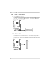
The IDE connector can connect a master and a slave drive, so you can connect up to two drives. 40 39 2 1 10 Motherboard Manual 2.4 CONNECTORS AND SLOTS FDD1: Floppy Disk Connector The motherboard provides a standard floppy disk connector that provides PIO Mode 0~4, Bus Master, and Ultra DMA 33/66/100/133 functionality. This connector supports the provided floppy drive ribbon cables. 2 34 1 33 IDE1: IDE/ATAPI Connector The motherboard has a 32-bit Enhanced PCI IDE Controller that supports 360K, 720K, 1.2M, 1.44M and 2.88M floppy disk types.
The IDE connector can connect a master and a slave drive, so you can connect up to two drives. 40 39 2 1 10 Motherboard Manual 2.4 CONNECTORS AND SLOTS FDD1: Floppy Disk Connector The motherboard provides a standard floppy disk connector that provides PIO Mode 0~4, Bus Master, and Ultra DMA 33/66/100/133 functionality. This connector supports the provided floppy drive ribbon cables. 2 34 1 33 IDE1: IDE/ATAPI Connector The motherboard has a 32-bit Enhanced PCI IDE Controller that supports 360K, 720K, 1.2M, 1.44M and 2.88M floppy disk types.

Setup Manual
Page 14
... 4GB/s simultaneously per direction, for an aggregate of 2.5GB/s on the system, please make sure that both ATXPWR1 and ATXPWR2 connectors have been plugged-in. Motherboard Manual ATXPWR2: ATX Power Source Connector Connecting this connector provides +12V to CPU power circuit. 1 4 2 3 Pin Assignment 1 +12V 2 +12V 3 Ground 4 Ground Note: Before you power on...
... 4GB/s simultaneously per direction, for an aggregate of 2.5GB/s on the system, please make sure that both ATXPWR1 and ATXPWR2 connectors have been plugged-in. Motherboard Manual ATXPWR2: ATX Power Source Connector Connecting this connector provides +12V to CPU power circuit. 1 4 2 3 Pin Assignment 1 +12V 2 +12V 3 Ground 4 Ground Note: Before you power on...
Setup Manual
Page 16
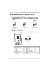
It allows user to set up jumpers. Motherboard Manual CHAPTER 3: HEADERS & JUMPERS SETUP 3.1 HOW TO SETUP JUMPERS The illustration shows how to connect the PC case's front panel switch functions. When the jumper cap ...
It allows user to set up jumpers. Motherboard Manual CHAPTER 3: HEADERS & JUMPERS SETUP 3.1 HOW TO SETUP JUMPERS The illustration shows how to connect the PC case's front panel switch functions. When the jumper cap ...

Setup Manual
Page 18
Motherboard Manual F_AUDIO1: Front Panel Audio Header This header allows user to connect the PCI bracket SPDIF output header. 13 Pin Assignment 1 +5V 2 SPDIF_OUT 3 Ground 16 This header allows only HD audio front panel connector; AC'97 connector is not acceptable. 2 10 1 9 Pin Assignment 1 Mic Left in 2 Ground 3 Mic Right in 4 GPIO 5 Right line in 6 Jack Sense 7 Front Sense 8 Key 9 Left line in 10 Jack Sense JSPDIFOUT1: Digital Audio-out Connector This connector allows user to connect the front audio output cable with the PC front panel.
Motherboard Manual F_AUDIO1: Front Panel Audio Header This header allows user to connect the PCI bracket SPDIF output header. 13 Pin Assignment 1 +5V 2 SPDIF_OUT 3 Ground 16 This header allows only HD audio front panel connector; AC'97 connector is not acceptable. 2 10 1 9 Pin Assignment 1 Mic Left in 2 Ground 3 Mic Right in 4 GPIO 5 Right line in 6 Jack Sense 7 Front Sense 8 Key 9 Left line in 10 Jack Sense JSPDIFOUT1: Digital Audio-out Connector This connector allows user to connect the front audio output cable with the PC front panel.

Setup Manual
Page 20
JUSBV2: +5V STB for USB ports at USB1/RJ45USB1. Pin 2-3 Close: JUSBV1: +5V STB for USB ports at F_USB1/F_USB2. JUSBV1 3 1 3 1 JUSBV2 3 1 Pin 1-2 close 3 1 Pin 2-3 close JKB_PWR: Power Source Header for PS/2 Keyboard and Mouse 3 3 1 1 Pin 1-2 close +5V for PS/2 keyboard and mouse. 3 1 Pin 2-3 close +5V STB for PS/2 keyboard and mouse. 18 JUSBV2: +5V for USB ports at USB1/RJ45USB1. Motherboard Manual JUSBV1/JUSBV2: Power Source Headers for USB Ports Pin 1-2 Close: JUSBV1: +5V for USB ports at F_USB1/F_USB2.
JUSBV2: +5V STB for USB ports at USB1/RJ45USB1. Pin 2-3 Close: JUSBV1: +5V STB for USB ports at F_USB1/F_USB2. JUSBV1 3 1 3 1 JUSBV2 3 1 Pin 1-2 close 3 1 Pin 2-3 close JKB_PWR: Power Source Header for PS/2 Keyboard and Mouse 3 3 1 1 Pin 1-2 close +5V for PS/2 keyboard and mouse. 3 1 Pin 2-3 close +5V STB for PS/2 keyboard and mouse. 18 JUSBV2: +5V for USB ports at USB1/RJ45USB1. Motherboard Manual JUSBV1/JUSBV2: Power Source Headers for USB Ports Pin 1-2 Close: JUSBV1: +5V for USB ports at F_USB1/F_USB2.
Setup Manual
Page 22
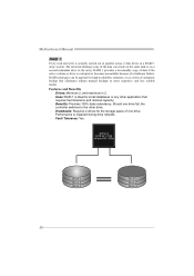
Motherboard Manual RAID 1: Every read and write is ideal for small databases or any other drive. Drawbacks: Requires 2 drives for high-availability solutions, or as a form ... drives in the array. Performance is corrupted or becomes unavailable because of one drive fail, the controller switches to the other application that eliminates tedious manual backups to more expensive and less reliable media. Block 1 Block 2 Block 3 20 Block 1 Block 2 Block 3 RAID techniques can be applied for the storage space of...
Motherboard Manual RAID 1: Every read and write is ideal for small databases or any other drive. Drawbacks: Requires 2 drives for high-availability solutions, or as a form ... drives in the array. Performance is corrupted or becomes unavailable because of one drive fail, the controller switches to the other application that eliminates tedious manual backups to more expensive and less reliable media. Block 1 Block 2 Block 3 20 Block 1 Block 2 Block 3 RAID techniques can be applied for the storage space of...

Setup Manual
Page 24
.... Features and Benefits Drives: Minimum 3. Uses: RAID 5 is placed on a different drive from those used to download the NVIDIA RAID User's Guide. 22 Motherboard Manual RAID 5: RAID 5 stripes both data and parity information across all the drives in the array. Fault tolerance is maintained by ensuring that the parity information...
.... Features and Benefits Drives: Minimum 3. Uses: RAID 5 is placed on a different drive from those used to download the NVIDIA RAID User's Guide. 22 Motherboard Manual RAID 5: RAID 5 stripes both data and parity information across all the drives in the array. Fault tolerance is maintained by ensuring that the parity information...
Setup Manual
Page 25
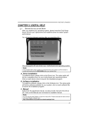
...latest version of Acrobat Reader software from the paperback manual, we also provide manual in the Driver CD. MCP6P3/N68S3 CHAPTER 5: USEFUL HELP 5.1 DRIVER INSTALLATION NOTE After you insert the CD The setup guide will auto detect your motherboard and operating system. Note: If this window ... Click on each device driver to launch the installation program. Note: You will list the compatible driver for your motherboard and operating system. B. Manual Aside from http://www.adobe.com/products/acrobat/readstep2.html 23 A. The setup guide will list the software available for...
...latest version of Acrobat Reader software from the paperback manual, we also provide manual in the Driver CD. MCP6P3/N68S3 CHAPTER 5: USEFUL HELP 5.1 DRIVER INSTALLATION NOTE After you insert the CD The setup guide will auto detect your motherboard and operating system. Note: If this window ... Click on each device driver to launch the installation program. Note: You will list the compatible driver for your motherboard and operating system. B. Manual Aside from http://www.adobe.com/products/acrobat/readstep2.html 23 A. The setup guide will list the software available for...
Setup Manual
Page 26
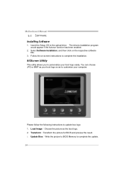
Insert the Setup CD to personalize your boot logo easily. Load Image:Choose the picture as to complete the installation. Motherboard Manual 5.2 SOFTWARE Installing Software 1. BIOScreen Utility This utility allows you to the optical drive. You can choose JPG or BMP as your computer. Follow the on ...
Insert the Setup CD to personalize your boot logo easily. Load Image:Choose the picture as to complete the installation. Motherboard Manual 5.2 SOFTWARE Installing Software 1. BIOScreen Utility This utility allows you to the optical drive. You can choose JPG or BMP as your computer. Follow the on ...

Setup Manual
Page 28
...Remove the power cord from power supply for seconds. 3. Wait for seconds. 2. Power on the system again. 26 CPU fan speed is over heated, the motherboard will shutdown automatically to relief the CPU protection function. 1. CPU fan is placed evenly with the CPU speed. Or you can: 1. When the CPU is...: JCMOS1" section) 2. Wait for seconds, that means the CPU protection function has been activated. Plug in the power cord and boot up the system. Motherboard Manual 5.4 EXTRA INFORMATION CPU Overheated If the system shutdown automatically after power on system for seconds. 3.
...Remove the power cord from power supply for seconds. 3. Wait for seconds. 2. Power on the system again. 26 CPU fan speed is over heated, the motherboard will shutdown automatically to relief the CPU protection function. 1. CPU fan is placed evenly with the CPU speed. Or you can: 1. When the CPU is...: JCMOS1" section) 2. Wait for seconds, that means the CPU protection function has been activated. Plug in the power cord and boot up the system. Motherboard Manual 5.4 EXTRA INFORMATION CPU Overheated If the system shutdown automatically after power on system for seconds. 3.

Setup Manual
Page 46
Motherboard Manual JAPANESE 仕様 Socket AM3 AMD 64 32ビットと64 CPU AMD Phenom II/ Athlon II 能です 95W) 2.0 2.0 GT/s FSB ート2.0 GeForce 6150 SE/nForce 430 (MCP6P3 GeForce 7025/nForce 630a (N68S3) DDR3 DIMM x... サポート ITE 8718F Super I/O H/Wモニター Super I/O ITE GeForce 6150 SE/nForce 430 (MCP6P3) ス GeForce 7025/nForce 630a (N68S3) 512MBです(under OS) IDE 統合IDE Ultra DMA 33 / ...
Motherboard Manual JAPANESE 仕様 Socket AM3 AMD 64 32ビットと64 CPU AMD Phenom II/ Athlon II 能です 95W) 2.0 2.0 GT/s FSB ート2.0 GeForce 6150 SE/nForce 430 (MCP6P3 GeForce 7025/nForce 630a (N68S3) DDR3 DIMM x... サポート ITE 8718F Super I/O H/Wモニター Super I/O ITE GeForce 6150 SE/nForce 430 (MCP6P3) ス GeForce 7025/nForce 630a (N68S3) 512MBです(under OS) IDE 統合IDE Ultra DMA 33 / ...
Bios Setup
Page 2
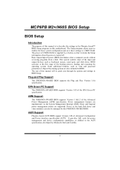
...such as virus and password protection or chipset fine-tuning options are implemented via the System Management Interrupt (SMI). The rest of this manual will to CMOS RAM. APM Support This PHOENIX-AWARD BIOS supports Version 1.1&1.2 of the booting process, loading and executing the operating system... This system controls most of the input and output devices such as defined in the Phoenix-Award™ BIOS Setup program on this motherboard. Sleep and Suspend power management modes are supported. Power to describe the settings in the ACPI specification, developed by a battery so ...
...such as virus and password protection or chipset fine-tuning options are implemented via the System Management Interrupt (SMI). The rest of this manual will to CMOS RAM. APM Support This PHOENIX-AWARD BIOS supports Version 1.1&1.2 of the booting process, loading and executing the operating system... This system controls most of the input and output devices such as defined in the Phoenix-Award™ BIOS Setup program on this motherboard. Sleep and Suspend power management modes are supported. Power to describe the settings in the ACPI specification, developed by a battery so ...


