

M7VIG user's manual
Page 3
... 1-2 1.1.1 Hardware...1-2 1.1.2 Software...1-6 1.1.3 Accessories ...1-6 1.2 Motherboard Installation 1-7 1.2.1 System Block Diagram 1-7 1.2.2 Layout of Motherboard 1-8 1.2.3 Quick Reference 1-9 1.3 CPU Installation 1-10 1.3.1 CPU Installation Procedure: Socket A 1-10 1.3.2 CPU Frequency Selection: JCLK1 1-11 1.3.3 CPU Fan Connector: JCFAN1 1-12 1.3.4 System Fan Connector: JSFAN1 1-12 1.4 ...
... 1-2 1.1.1 Hardware...1-2 1.1.2 Software...1-6 1.1.3 Accessories ...1-6 1.2 Motherboard Installation 1-7 1.2.1 System Block Diagram 1-7 1.2.2 Layout of Motherboard 1-8 1.2.3 Quick Reference 1-9 1.3 CPU Installation 1-10 1.3.1 CPU Installation Procedure: Socket A 1-10 1.3.2 CPU Frequency Selection: JCLK1 1-11 1.3.3 CPU Fan Connector: JCFAN1 1-12 1.3.4 System Fan Connector: JSFAN1 1-12 1.4 ...

M7VIG user's manual
Page 6
This motherboard is designed to take advantage of the latest industry technology to you with the ultimate solution in microarchitecture design, graphics performance, system bus design, cache architecture and much more. 8 Complies with industry software and hardware standards. M7VIG Highlights: 8 Contains on ...for IDE devices such as Windows 2000, Windows ME, Windows XP, LINUX and SCO UNIX. 1-1 Chapter 1 Motherboard Description Introduction System Overview Congratulations on board IDE facilities for full compliance and compatibility with PC MicroATX form factor specifications....
This motherboard is designed to take advantage of the latest industry technology to you with the ultimate solution in microarchitecture design, graphics performance, system bus design, cache architecture and much more. 8 Complies with industry software and hardware standards. M7VIG Highlights: 8 Contains on ...for IDE devices such as Windows 2000, Windows ME, Windows XP, LINUX and SCO UNIX. 1-1 Chapter 1 Motherboard Description Introduction System Overview Congratulations on board IDE facilities for full compliance and compatibility with PC MicroATX form factor specifications....

M7VIG user's manual
Page 7
...; Chipset - Green Function − Support power management operation via BIOS. − Power down timer from 1 to AMD Athlon TM XP 2100+ CPU core speeds. Chapter 1 Motherboard Description 1. Motherboard Description 1.1 Features 1.1.1 Hardware CPU − − Single AMD Socket-A for Athlon TM (Thunderbird TM )/ Athlon TM XP/ Duron TM processors.
...; Chipset - Green Function − Support power management operation via BIOS. − Power down timer from 1 to AMD Athlon TM XP 2100+ CPU core speeds. Chapter 1 Motherboard Description 1. Motherboard Description 1.1 Features 1.1.1 Hardware CPU − − Single AMD Socket-A for Athlon TM (Thunderbird TM )/ Athlon TM XP/ Duron TM processors.
M7VIG user's manual
Page 8
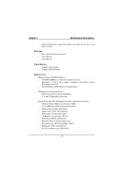
... Direct X texture compression. − Next generation, 128-bit 2D graphics engine. − High quality DVD video playback. − 2D / 3D resolutions up to 1920x1440. 1-3 Chapter 1 Motherboard Description − Wakes from power saving sleep mode at the press of any key or any mouse activity.
... Direct X texture compression. − Next generation, 128-bit 2D graphics engine. − High quality DVD video playback. − 2D / 3D resolutions up to 1920x1440. 1-3 Chapter 1 Motherboard Description − Wakes from power saving sleep mode at the press of any key or any mouse activity.

M7VIG user's manual
Page 9
.../ 66/100/133 Bus Master Mode. − Supports IDE interface with CD-ROM. − Supports high capacity hard disk drives. − Supports LBA mode. Chapter 1 Motherboard Description 3D Rendering Features − Single-pass multiple textures. − Anisotropic filtering. − 8-bit stencil buffer. − 32-bit true color rendering. − Specular lighting...
.../ 66/100/133 Bus Master Mode. − Supports IDE interface with CD-ROM. − Supports high capacity hard disk drives. − Supports LBA mode. Chapter 1 Motherboard Description 3D Rendering Features − Single-pass multiple textures. − Anisotropic filtering. − 8-bit stencil buffer. − 32-bit true color rendering. − Specular lighting...

M7VIG user's manual
Page 10
...) − 24.4 cm X 24.4 cm (W x L) 1-5 Hardware Monitor Function − CPU Fan and System Fan Speed Monitor. − CPU Temperature Monitor. − System Voltage Monitor. Chapter 1 Motherboard Description (2) Enhanced Parallel Port (EPP). (3) Extended Capabilities Port (ECP). (4) Normal. − Supports two serial ports, 16550 UART. − Supports one Infrared transmission (IR). − Supports...
...) − 24.4 cm X 24.4 cm (W x L) 1-5 Hardware Monitor Function − CPU Fan and System Fan Speed Monitor. − CPU Temperature Monitor. − System Voltage Monitor. Chapter 1 Motherboard Description (2) Enhanced Parallel Port (EPP). (3) Extended Capabilities Port (ECP). (4) Normal. − Supports two serial ports, 16550 UART. − Supports one Infrared transmission (IR). − Supports...

M7VIG user's manual
Page 11
Supports ACPI. Supports USB Function. Supports APM1.2. Chapter 1 Motherboard Description 1.1.2 Software BIOS AWARD legal BIOS. Operating System − Offers the highest performance for MS-DOS, Windows 2000, Windows ME, Windows XP, SCO UNIX etc. 1.1.3 Accessories − HDD Cable. − FDD Cable. − Flash Memory Writer for BIOS Update. − USB2 Cable (Optional). − Rear I/O Panel for Micro ATX Case (Optional). − Fully Setup Driver CD. 1-6
Supports ACPI. Supports USB Function. Supports APM1.2. Chapter 1 Motherboard Description 1.1.2 Software BIOS AWARD legal BIOS. Operating System − Offers the highest performance for MS-DOS, Windows 2000, Windows ME, Windows XP, SCO UNIX etc. 1.1.3 Accessories − HDD Cable. − FDD Cable. − Flash Memory Writer for BIOS Update. − USB2 Cable (Optional). − Rear I/O Panel for Micro ATX Case (Optional). − Fully Setup Driver CD. 1-6

M7VIG user's manual
Page 12
... LAN CONN. SUPPORTS 3 PCI SLOTS SER. CONN. SUPPORT TELEPHONY CONN. AC' 97 CODEC VT8233A PCI BUS 4 USB CONN. M7VIG Micro ATX(FSB: 133/100MHz) SUPPORTS 4 DIMMS SUPPORT 1 AGP SLOT SER. Chapter 1 Motherboard Description 1.2 Motherboard Installation 1.2.1 System Block Diagram AMD K7 PROCESSOR CLOCK ICW312-02 14.318MHZ CONTROL HOST BUS ADD DATA HOST BUS...
... LAN CONN. SUPPORTS 3 PCI SLOTS SER. CONN. SUPPORT TELEPHONY CONN. AC' 97 CODEC VT8233A PCI BUS 4 USB CONN. M7VIG Micro ATX(FSB: 133/100MHz) SUPPORTS 4 DIMMS SUPPORT 1 AGP SLOT SER. Chapter 1 Motherboard Description 1.2 Motherboard Installation 1.2.1 System Block Diagram AMD K7 PROCESSOR CLOCK ICW312-02 14.318MHZ CONTROL HOST BUS ADD DATA HOST BUS...

M7VIG user's manual
Page 13
Chapter 1 Motherboard Description 1.2.2 Layout of Motherboard Model No. IDE2 24 23 FLOPPY DISK CONN. FDD1 1 21 JPANEL1 JSFAN1 1-8 IDE1 PCI2 VT 8233A PCI3 Winbond 2 10 JWOL1 W83697HF 1 9 JUSB2 1 SECONDARY IDE CONN. M7VIG JKBMS1 JATXPWR1 JUSBLAN1 JCOM1 JPRNT1 JCFAN1 1 GAME Port DDR1 DDR2 SDR1 SDR2 JVGA1 JSPKR1 SP-OUT JLIN1 LINE-IN JMIC1 MIC-IN JAUD GAME LAN CHIP 2 10 19 JTAD1 1 1 J10 1 1 KM 266 BAT1 1 JCMOS1 PCI1 JDIMMVOLT 2 8 1 7 PRIMARY IDE CONN.
Chapter 1 Motherboard Description 1.2.2 Layout of Motherboard Model No. IDE2 24 23 FLOPPY DISK CONN. FDD1 1 21 JPANEL1 JSFAN1 1-8 IDE1 PCI2 VT 8233A PCI3 Winbond 2 10 JWOL1 W83697HF 1 9 JUSB2 1 SECONDARY IDE CONN. M7VIG JKBMS1 JATXPWR1 JUSBLAN1 JCOM1 JPRNT1 JCFAN1 1 GAME Port DDR1 DDR2 SDR1 SDR2 JVGA1 JSPKR1 SP-OUT JLIN1 LINE-IN JMIC1 MIC-IN JAUD GAME LAN CHIP 2 10 19 JTAD1 1 1 J10 1 1 KM 266 BAT1 1 JCMOS1 PCI1 JDIMMVOLT 2 8 1 7 PRIMARY IDE CONN.

M7VIG user's manual
Page 14
... (JTAD1) G. Wake-On-LAN Header (JWOL1) KM 266 DDR1 DDR2 S SDR1 SDR2 R BAT1 Q L. CMOS Clear Function (JCMOS1) R. SECONDARY IDE CONN. Front Panel Connector (JPANEL1) P. Chapter 1 Motherboard Description 1.2.3 Quick Reference I . FLOPPY DISK CONN. N O P A. Front Audio Header (JAUDIO1) D. Cd Audio-In Header (JCDIN2) H. CNR Codec Primary/Secondary Select (J10) (Optional) I HG F E D C B A V U LAN CHIP...
... (JTAD1) G. Wake-On-LAN Header (JWOL1) KM 266 DDR1 DDR2 S SDR1 SDR2 R BAT1 Q L. CMOS Clear Function (JCMOS1) R. SECONDARY IDE CONN. Front Panel Connector (JPANEL1) P. Chapter 1 Motherboard Description 1.2.3 Quick Reference I . FLOPPY DISK CONN. N O P A. Front Audio Header (JAUDIO1) D. Cd Audio-In Header (JCDIN2) H. CNR Codec Primary/Secondary Select (J10) (Optional) I HG F E D C B A V U LAN CHIP...

M7VIG user's manual
Page 15
Locate Pin A in the CPU. Match Pin A with the white dot/cut edge in the socket and look for the white dot or cut edge then insert the CPU. 3. Press the lever down. 4. Put the fan on the CPU by buckling it, and then put the fan's powerport into the JCFAN1, then the installation will be completed. 1-10 Chapter 1 Motherboard Description 1.3 CPU Installation 1.3.1 CPU Installation Procedure: Socket A CPU 1. Pull the lever sideways away from the socket then raise the lever up to a 90-degree angle. 2.
Locate Pin A in the CPU. Match Pin A with the white dot/cut edge in the socket and look for the white dot or cut edge then insert the CPU. 3. Press the lever down. 4. Put the fan on the CPU by buckling it, and then put the fan's powerport into the JCFAN1, then the installation will be completed. 1-10 Chapter 1 Motherboard Description 1.3 CPU Installation 1.3.1 CPU Installation Procedure: Socket A CPU 1. Pull the lever sideways away from the socket then raise the lever up to a 90-degree angle. 2.

M7VIG user's manual
Page 16
FLOPPY DISK CONN. 1 JSFAN1 1.3.2 CPU Frequency Selection: JCLK1 JCKL1 *200MHz Close 266MHz Open NOTES: The " * " mark indicate primitive value. 1-11 SECONDARY IDE CONN. Chapter 1 Motherboard Description JCFAN1 1 DDR1 DDR2 SDR1 SDR2 LAN CHIP KM 266 BAT1 VT8233A Winbond 83679HF PRIMARY IDE CONN.
FLOPPY DISK CONN. 1 JSFAN1 1.3.2 CPU Frequency Selection: JCLK1 JCKL1 *200MHz Close 266MHz Open NOTES: The " * " mark indicate primitive value. 1-11 SECONDARY IDE CONN. Chapter 1 Motherboard Description JCFAN1 1 DDR1 DDR2 SDR1 SDR2 LAN CHIP KM 266 BAT1 VT8233A Winbond 83679HF PRIMARY IDE CONN.

M7VIG user's manual
Page 17
Chapter 1 Motherboard Description 1.3.3 CPU Fan Connector: JCFAN1 Pin No. 1 2 3 Assignment Ground +12V Sense 1.3.4 System Fan Connector: JSFAN1 Pin No. 1 2 3 Assignment Ground +12V Sense 1-12
Chapter 1 Motherboard Description 1.3.3 CPU Fan Connector: JCFAN1 Pin No. 1 2 3 Assignment Ground +12V Sense 1.3.4 System Fan Connector: JSFAN1 Pin No. 1 2 3 Assignment Ground +12V Sense 1-12

M7VIG user's manual
Page 18
Chapter 1 Motherboard Description 1.4 RAM Module Installation 1.4.1 DDR SDRAM DRAM Type: 2.5V Unbuffered DDR SDRAM PC1600/ PC2100/ PC2700 Type required. 128MB/ 256MB/ 512MB/ 1GB DIMM Module (184 pin) ...
Chapter 1 Motherboard Description 1.4 RAM Module Installation 1.4.1 DDR SDRAM DRAM Type: 2.5V Unbuffered DDR SDRAM PC1600/ PC2100/ PC2700 Type required. 128MB/ 256MB/ 512MB/ 1GB DIMM Module (184 pin) ...

M7VIG user's manual
Page 19
Chapter 1 Motherboard Description 1.4.2 SDRAM DRAM Type: 3.3V Unbuffered SDRAM PC100/ PC133 Type required. 128MB/ 256MB/ 512MB DIMM Module (168 pin) Total Memory Size with unbuffer DIMMs (Only for reference) Total Memory DIMM 1 DIMM 2 Size (MB) 128 M 128 M ---- 256 M 256 M ---- 512 M 256 M 384 M 640 M 512 M 128 M 256 M 512 M ---128 M 128 M 128 M 384 M 512 M 128 M 256 M 256 M 256 M 768 M 640 M 768 M 512 M 128 M 256 M 256 M 512 M 512 M 1024 M 2 G 512 M 1G 512 M 1G 1-14
Chapter 1 Motherboard Description 1.4.2 SDRAM DRAM Type: 3.3V Unbuffered SDRAM PC100/ PC133 Type required. 128MB/ 256MB/ 512MB DIMM Module (168 pin) Total Memory Size with unbuffer DIMMs (Only for reference) Total Memory DIMM 1 DIMM 2 Size (MB) 128 M 128 M ---- 256 M 256 M ---- 512 M 256 M 384 M 640 M 512 M 128 M 256 M 512 M ---128 M 128 M 128 M 384 M 512 M 128 M 256 M 256 M 256 M 768 M 640 M 768 M 512 M 128 M 256 M 256 M 512 M 512 M 1024 M 2 G 512 M 1G 512 M 1G 1-14

M7VIG user's manual
Page 20
The Mounting Holes and plastic tabs should fit over the edge and hold the DDR DIMM memory modules in one direction. 2. Chapter 1 Motherboard Description 1.4.3 How to install DDR/SDRAM DIMM Module DDR SDRAM: Single Sided DIMM Double Sided DIMM 1. Insert the DDR DIMM memory modules into the socket at a 90-degree angle, then push down vertically so that it will fit into the slot in place. 1-15 The DDR DIMM socket has a " Plastic Safety Tab", and the DDR DIMM memory module has an Asymmetrical notch", so the DDR DIMM memory module can only fit into the place. 3. Push the tabs out.
The Mounting Holes and plastic tabs should fit over the edge and hold the DDR DIMM memory modules in one direction. 2. Chapter 1 Motherboard Description 1.4.3 How to install DDR/SDRAM DIMM Module DDR SDRAM: Single Sided DIMM Double Sided DIMM 1. Insert the DDR DIMM memory modules into the socket at a 90-degree angle, then push down vertically so that it will fit into the slot in place. 1-15 The DDR DIMM socket has a " Plastic Safety Tab", and the DDR DIMM memory module has an Asymmetrical notch", so the DDR DIMM memory module can only fit into the place. 3. Push the tabs out.

M7VIG user's manual
Page 21
Push the tabs out. The Mounting Holes and plastic tabs should fit over the edge and hold the SDRAM DIMM memory modules in one direction. 2. Chapter 1 SDRAM: Motherboard Description 1. Insert the SDRAM DIMM memory modules into the socket at a 90-degree angle, then push down vertically so that it will fit into the slot in place. 1-16 The SDRAM DIMM socket has a " Plastic Safety Tab", and the SDRAM DIMM memory module has an Asymmetrical notch", so the SDRAM DIMM memory module can only fit into the place. 3.
Push the tabs out. The Mounting Holes and plastic tabs should fit over the edge and hold the SDRAM DIMM memory modules in one direction. 2. Chapter 1 SDRAM: Motherboard Description 1. Insert the SDRAM DIMM memory modules into the socket at a 90-degree angle, then push down vertically so that it will fit into the slot in place. 1-16 The SDRAM DIMM socket has a " Plastic Safety Tab", and the SDRAM DIMM memory module has an Asymmetrical notch", so the SDRAM DIMM memory module can only fit into the place. 3.

M7VIG user's manual
Page 22
Chapter 1 Motherboard Description 1.5 Slots The slots in this motherboard are a mean of the basic system. With these efficient facilities, you can increase the motherboard's capabilities by adding hardware that performs tasks that are not part of adding or enhancing the motherboard's features and capabilities. SECONDARY IDE CONN. DDR1 DDR2 SDR1 SDR2 AGP Slot PCI Slot CNR Slot LAN CHIP KM 266 BAT1 VT8233A Winbond 83679HF PRIMARY IDE CONN. Expansion slots are designed to hold expansion cards and connect them to the system bus. FLOPPY DISK CONN. 1-17
Chapter 1 Motherboard Description 1.5 Slots The slots in this motherboard are a mean of the basic system. With these efficient facilities, you can increase the motherboard's capabilities by adding hardware that performs tasks that are not part of adding or enhancing the motherboard's features and capabilities. SECONDARY IDE CONN. DDR1 DDR2 SDR1 SDR2 AGP Slot PCI Slot CNR Slot LAN CHIP KM 266 BAT1 VT8233A Winbond 83679HF PRIMARY IDE CONN. Expansion slots are designed to hold expansion cards and connect them to the system bus. FLOPPY DISK CONN. 1-17

M7VIG user's manual
Page 23
...expansion slots. and therefore, requires a video card for improved video efficiency and performance, especially with 3D graphics. 1.5.2 PCI (Peripheral Component Interconnect) Slots This motherboard is equipped with an Accelerated Graphics Port (AGP). An AGP card will attach directly to that video card. Tis... motherboard supports video cards for expansion cards supplanted the older ISA bus standard in video facilities; PCI stands for Peripheral Component Interconnect, and it is...
...expansion slots. and therefore, requires a video card for improved video efficiency and performance, especially with 3D graphics. 1.5.2 PCI (Peripheral Component Interconnect) Slots This motherboard is equipped with an Accelerated Graphics Port (AGP). An AGP card will attach directly to that video card. Tis... motherboard supports video cards for expansion cards supplanted the older ISA bus standard in video facilities; PCI stands for Peripheral Component Interconnect, and it is...

M7VIG user's manual
Page 24
... 1-2 FLOPPY DISK CONN. JATXPWR1 DDR1 DDR2 SDR1 SDR2 J10 1 LAN CHIP KM 266 VT8233A 2 10 1 9 JUSB2 Winbond 83679HF JWOL1 1 BAT1 1 JCMOS1 PRIMARY IDE CONN. Chapter 1 Motherboard Description 1.6 Connectors, Headers & Jumpers The connectors, headers and jumpers introduced below provide you lots of capabilities such as power supply, front panel signal revelation, IDE...
... 1-2 FLOPPY DISK CONN. JATXPWR1 DDR1 DDR2 SDR1 SDR2 J10 1 LAN CHIP KM 266 VT8233A 2 10 1 9 JUSB2 Winbond 83679HF JWOL1 1 BAT1 1 JCMOS1 PRIMARY IDE CONN. Chapter 1 Motherboard Description 1.6 Connectors, Headers & Jumpers The connectors, headers and jumpers introduced below provide you lots of capabilities such as power supply, front panel signal revelation, IDE...


