Setup Manual
Page 2
Table of Contents Chapter 1: Introduction 1 1.1 Motherboard Features 1 1.2 Package List 3 1.3 Layout and Components 4 Chapter 2: Hardware Installation 5 2.1 Installing Central Processing Unit (CPU 5 2.2 FAN Headers 6 2.3 Installing System Memory 7 2.4 Connectors and Slots 8 Chapter 3: Headers & Jumpers ...
Table of Contents Chapter 1: Introduction 1 1.1 Motherboard Features 1 1.2 Package List 3 1.3 Layout and Components 4 Chapter 2: Hardware Installation 5 2.1 Installing Central Processing Unit (CPU 5 2.2 FAN Headers 6 2.3 Installing System Memory 7 2.4 Connectors and Slots 8 Chapter 3: Headers & Jumpers ...
Setup Manual
Page 3
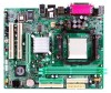
... DMA 33/ 66/100/133 Bus Master Mode. Supports DDR-266/333/400. System Memory Supports up to 2 DDR devices. Chi pset North Bridge: VIA K8M800. One CNR slot. One AGP 4x/8x compatible slot. Supports PIO mode 0~4. K8M800-M7A CHAPTER 1: INTRODUCTION 1.1 MOTHERBOARD FEATURES C PU Supports Socket 754.
... DMA 33/ 66/100/133 Bus Master Mode. Supports DDR-266/333/400. System Memory Supports up to 2 DDR devices. Chi pset North Bridge: VIA K8M800. One CNR slot. One AGP 4x/8x compatible slot. Supports PIO mode 0~4. K8M800-M7A CHAPTER 1: INTRODUCTION 1.1 MOTHERBOARD FEATURES C PU Supports Socket 754.
Setup Manual
Page 10
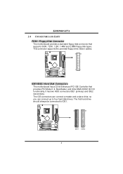
K8M800-M7A 2.4 CONNECTORS AND SLOTS FDD1: Floppy Disk Connector T he first hard drive should always be connected to four hard disk drives. It has two HDD connectors IDE1 (primary) and IDE2 (secondary). This connector supports the provided floppy drive ribbon cables. 34 33 2 1 IDE1/IDE2: Hard Disk Connectors The motherboard... a 32-bit Enhanced PCI IDE Controller that supports 360K, 720K, 1.2M, 1.44M and 2.88M floppy disk types. T he motherboard provides a standard floppy disk connector that provides PIO Mode 0~4, Bus Master, and Ultra DMA 33/66/100/133 functionality. The IDE ...
K8M800-M7A 2.4 CONNECTORS AND SLOTS FDD1: Floppy Disk Connector T he first hard drive should always be connected to four hard disk drives. It has two HDD connectors IDE1 (primary) and IDE2 (secondary). This connector supports the provided floppy drive ribbon cables. 34 33 2 1 IDE1/IDE2: Hard Disk Connectors The motherboard... a 32-bit Enhanced PCI IDE Controller that supports 360K, 720K, 1.2M, 1.44M and 2.88M floppy disk types. T he motherboard provides a standard floppy disk connector that provides PIO Mode 0~4, Bus Master, and Ultra DMA 33/66/100/133 functionality. The IDE ...
Setup Manual
Page 11
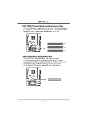
K8M800-M7A PCI1~PCI3: Peripheral Component Interconnect Slots This motherboard is designated as 32 bits. This PCI slot is equipped with 3 standard PCI slots. P CI 1 P CI 2 P CI 3 AGP1: Accel erated Graphi cs Port Sl ot ... of AGP technology for PCI slots, but it is also equipped with 3D graphics. 9 An AGP card will attach directly to that video card. This motherboard supports video cards for improved video efficiency and performance, especially with an Accelerated Graphics Port (AGP). PCI stands for Peripheral Component Interconnect, and it is...
K8M800-M7A PCI1~PCI3: Peripheral Component Interconnect Slots This motherboard is designated as 32 bits. This PCI slot is equipped with 3 standard PCI slots. P CI 1 P CI 2 P CI 3 AGP1: Accel erated Graphi cs Port Sl ot ... of AGP technology for PCI slots, but it is also equipped with 3D graphics. 9 An AGP card will attach directly to that video card. This motherboard supports video cards for improved video efficiency and performance, especially with an Accelerated Graphics Port (AGP). PCI stands for Peripheral Component Interconnect, and it is...
Setup Manual
Page 17
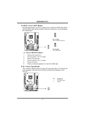
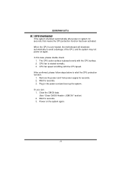
... has been triggered, it allows user to restore the BIOS saf e setting and the CMOS data, please carefully f ollow the procedures to avoid damaging the motherboard. 1 3 Pin 1-2 Close: Normal Operation (default). 1 1 3 3 Pin 2-3 Close: Clear CMOS data. ※ Clear CMOS Proce dures: 1. Remov e AC power line. 2....JCI1: Chassis O pen Heade r This connector allows system to monitor PC case open signal 2 Ground 2 1 15 Pin Assignment 1 Case open status. K8M800-M7A JCMO S1: Cle ar CMOS Heade r By placing the jumper on pin2-3, it will record to the CMOS and show the message on the...
... has been triggered, it allows user to restore the BIOS saf e setting and the CMOS data, please carefully f ollow the procedures to avoid damaging the motherboard. 1 3 Pin 1-2 Close: Normal Operation (default). 1 1 3 3 Pin 2-3 Close: Clear CMOS data. ※ Clear CMOS Proce dures: 1. Remov e AC power line. 2....JCI1: Chassis O pen Heade r This connector allows system to monitor PC case open signal 2 Ground 2 1 15 Pin Assignment 1 Case open status. K8M800-M7A JCMO S1: Cle ar CMOS Heade r By placing the jumper on pin2-3, it will record to the CMOS and show the message on the...
Setup Manual
Page 18
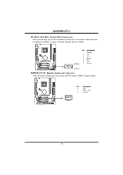
K8M800-M7A JSATA1~JSATA2: Se rial ATA Connectors The motherboard has a PCI to SATA Controller with 2 channels SATA interf ace, it satisfies the SATA 1.0 spec and with transfer rate of 1.5GB/s. 741 Pin Assignment 1 Ground 2 TX+ 3 TX4 Ground 5 RX6 RX+ 7 Ground JS ATA1 JSPDIF_O UT1: Digital Audio-out Conne ctor This connector allows user to connect the PCI bracket SPDIF output header. 1 3 Pin Assignment 1 +5V 2 SPDIF_OUT 3 Ground 16
K8M800-M7A JSATA1~JSATA2: Se rial ATA Connectors The motherboard has a PCI to SATA Controller with 2 channels SATA interf ace, it satisfies the SATA 1.0 spec and with transfer rate of 1.5GB/s. 741 Pin Assignment 1 Ground 2 TX+ 3 TX4 Ground 5 RX6 RX+ 7 Ground JS ATA1 JSPDIF_O UT1: Digital Audio-out Conne ctor This connector allows user to connect the PCI bracket SPDIF output header. 1 3 Pin Assignment 1 +5V 2 SPDIF_OUT 3 Ground 16
Setup Manual
Page 19
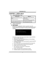
...automatically and restart. 9. Make a bootable floppy disk. 2. Confirm motherboard model and download the respectively BIOS from the Biostar website: www.biostar.com.tw 3. Download the Flash Utility "AWDFLASH.exe" from Biostar website. 4. System will boot-up the system, it means ...the BIOS contents are corrupted. Type "Awdflash xxxx.bf/sn/py/r" in DOS prompt. (xxxx means BIOS name.) 8. BIOS Update After you fail to update BIOS or BIOS is shown after boot-up to DOS prompt. 7. System will work properly. 17 K8M800...
...automatically and restart. 9. Make a bootable floppy disk. 2. Confirm motherboard model and download the respectively BIOS from the Biostar website: www.biostar.com.tw 3. Download the Flash Utility "AWDFLASH.exe" from Biostar website. 4. System will boot-up the system, it means ...the BIOS contents are corrupted. Type "Awdflash xxxx.bf/sn/py/r" in DOS prompt. (xxxx means BIOS name.) 8. BIOS Update After you fail to update BIOS or BIOS is shown after boot-up to DOS prompt. 7. System will work properly. 17 K8M800...
Setup Manual
Page 20
K8M800-M7A B. The CPU cooler surface is fulfilling with the CPU surface. 2. After confirmed, please follow steps below to avoid a damage of the CPU, and the ... supply for seconds. 3. CPU fan speed is placed evenly with the CPU speed. In this case, please double check: 1. CPU fan is over heated, the motherboard will shutdown automatically to relief the CPU protection function. 1. Wait for seconds. 2. Or you can: 1. Wait for seconds, that means the CPU protection function has...
K8M800-M7A B. The CPU cooler surface is fulfilling with the CPU surface. 2. After confirmed, please follow steps below to avoid a damage of the CPU, and the ... supply for seconds. 3. CPU fan speed is placed evenly with the CPU speed. In this case, please double check: 1. CPU fan is over heated, the motherboard will shutdown automatically to relief the CPU protection function. 1. Wait for seconds. 2. Or you can: 1. Wait for seconds, that means the CPU protection function has...
Setup Manual
Page 23
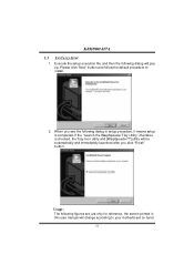
... according to i n stall . 2. Execute the setup execution file, and then the following dialog in this user manual will pop up. When you click "Finish" button. K8M800-M7A 5.3 INSTALLATION 1. If the "Launch the WarpSpeeder T ray Utility" checkbox is completed. Please click "Next" button and follow the default procedure to your...
... according to i n stall . 2. Execute the setup execution file, and then the following dialog in this user manual will pop up. When you click "Finish" button. K8M800-M7A 5.3 INSTALLATION 1. If the "Launch the WarpSpeeder T ray Utility" checkbox is completed. Please click "Next" button and follow the default procedure to your...
Setup Manual
Page 53
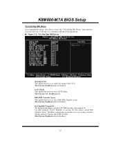
...), Disabled. The Choices: IDE, RAID (default). Select " Enabled" to enable the onchip Serial ATA. The Choices: Enabled (default), Disabled. 22 K8M800-M7A BIOS Setup VIA OnChip IDE Device If you highlight the literal " Press Enter" next to the " VIA OnChip IDE Device" label and then ...IDE channels. IDE DMA Transf er Access This option allows you to activate the first and/or second IDE interface. OnChip IDE Channel 0/1 The motherboard chipset contains a P CI IDE interface with the following options: „ Figure 5.1: VIA OnChip IDE Device OnChip SATA This option allows you to...
...), Disabled. The Choices: IDE, RAID (default). Select " Enabled" to enable the onchip Serial ATA. The Choices: Enabled (default), Disabled. 22 K8M800-M7A BIOS Setup VIA OnChip IDE Device If you highlight the literal " Press Enter" next to the " VIA OnChip IDE Device" label and then ...IDE channels. IDE DMA Transf er Access This option allows you to activate the first and/or second IDE interface. OnChip IDE Channel 0/1 The motherboard chipset contains a P CI IDE interface with the following options: „ Figure 5.1: VIA OnChip IDE Device OnChip SATA This option allows you to...
Setup Manual
Page 61
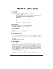
...AGP driver to the " Off" status when AC power is eventually turned on , 5VSB fro m the Power Supply is not supplying power, the motherboard uses the motherboard battery (3V). There are 3 sources that provide current to the video buffer . "Off " (default) Means always set CMOS to the " ...On" status when AC power is lost . K8M800-M7A BIOS Setup Video Off Method This option determines the manner in MODEM use. The system ...
...AGP driver to the " Off" status when AC power is eventually turned on , 5VSB fro m the Power Supply is not supplying power, the motherboard uses the motherboard battery (3V). There are 3 sources that provide current to the video buffer . "Off " (default) Means always set CMOS to the " ...On" status when AC power is lost . K8M800-M7A BIOS Setup Video Off Method This option determines the manner in MODEM use. The system ...


