
Setup Manual
Page 4
... (with Smart Fan function) x1 System Fan Power supply x1 Restore CMOS data to factory default x2 Eachconnector supports 2 front panel USB ports Motherboard Manual 1.3 MOT HERBOARD FEAT URES SPEC CPU Socket AM2 AMDSempron processors Supports Hyper Transport andCool=n=Quiet FSB Chipset Support HyperTransport K8M80 0 VT823 7R+ ITE IT8705 Supports up to 1.5 Gb/s.
... (with Smart Fan function) x1 System Fan Power supply x1 Restore CMOS data to factory default x2 Eachconnector supports 2 front panel USB ports Motherboard Manual 1.3 MOT HERBOARD FEAT URES SPEC CPU Socket AM2 AMDSempron processors Supports Hyper Transport andCool=n=Quiet FSB Chipset Support HyperTransport K8M80 0 VT823 7R+ ITE IT8705 Supports up to 1.5 Gb/s.

Setup Manual
Page 6
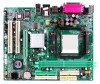
Motherboard Manual 1.5 MOT HERBOARD LAYOUT JKB MS1 JATX PWR1 DIMMA1 DIMMB1 F DD1 Socket A M2 JPRNT1 J CO M1 JVGA1 IDE1 IDE2 JUS B1 JUSBLAN1 JATXP WR2 JCFAN1 JAUDIO1 K8M800 Super I/O LAN AGP 1 BIOS PCI1 Codec PCI2 JAUDIO2 JCDIN1 JSPDIF_OUT1 JSFAN1 Not e: ■ repre sents the 1st pin. 4 BAT1 VT8237R+ JCMOS1 JSATA2 JUSB2 JUSB3 JS ATA1 J PA NE L1
Motherboard Manual 1.5 MOT HERBOARD LAYOUT JKB MS1 JATX PWR1 DIMMA1 DIMMB1 F DD1 Socket A M2 JPRNT1 J CO M1 JVGA1 IDE1 IDE2 JUS B1 JUSBLAN1 JATXP WR2 JCFAN1 JAUDIO1 K8M800 Super I/O LAN AGP 1 BIOS PCI1 Codec PCI2 JAUDIO2 JCDIN1 JSPDIF_OUT1 JSFAN1 Not e: ■ repre sents the 1st pin. 4 BAT1 VT8237R+ JCMOS1 JSATA2 JUSB2 JUSB3 JS ATA1 J PA NE L1

Setup Manual
Page 8
Connect the CPU FAN power cable to complete the installation. This completes the installation. 6 Step 5: Put the CPU Fan on the CPU and buckle it. Motherboard Manual Step 4: Hold the CPU down firmly, and then close the lever toward direct B to the JCFAN1.
Connect the CPU FAN power cable to complete the installation. This completes the installation. 6 Step 5: Put the CPU Fan on the CPU and buckle it. Motherboard Manual Step 4: Hold the CPU down firmly, and then close the lever toward direct B to the JCFAN1.

Setup Manual
Page 10
DDR2 module DIMMA1 DIMMB1 1. Unlock a DIMM slot by pressing the retaining clips outward. Insert the DIMM vertically and firmly into the slot until the retaining chip snap back in place and the DIMM is properly seated. Align a DIMM on the slot such that the notch on the DIMM matches the break on the Slot. 2. B. Memory Capacity DIMM Socket Location DIMMA1 DIMMB1 DDR Module 256MB/512MB/1GB *1 256MB/512MB/1GB *1 Total Memory Size Max memory 2GB. 8 Motherboard Manual 2.3 INST ALLING SYST EM MEMORY A.
DDR2 module DIMMA1 DIMMB1 1. Unlock a DIMM slot by pressing the retaining clips outward. Insert the DIMM vertically and firmly into the slot until the retaining chip snap back in place and the DIMM is properly seated. Align a DIMM on the slot such that the notch on the DIMM matches the break on the Slot. 2. B. Memory Capacity DIMM Socket Location DIMMA1 DIMMB1 DDR Module 256MB/512MB/1GB *1 256MB/512MB/1GB *1 Total Memory Size Max memory 2GB. 8 Motherboard Manual 2.3 INST ALLING SYST EM MEMORY A.

Setup Manual
Page 12
The f irst hard drive should always be connected to four hard disk drives. Motherboard Manual 2.4 CONNECT ORS AND SLOT S FDD1: Floppy Disk Conne ctor The motherboard prov ides a standard floppy disk connector that prov ides PIO Mode 0~4, Bus Master, and Ultra DMA 33/66/100/133 f unctionality. ...This connector supports the prov ided f loppy drive ribbon cables. 34 33 2 1 IDE1/IDE2: Hard Disk Conne ctors The motherboard has a 32-bit Enhanced PCI IDE Controller that supports 360K, 720K, 1.2M, 1.44M and 2.88M floppy disk ty pes. The IDE connectors can connect...
The f irst hard drive should always be connected to four hard disk drives. Motherboard Manual 2.4 CONNECT ORS AND SLOT S FDD1: Floppy Disk Conne ctor The motherboard prov ides a standard floppy disk connector that prov ides PIO Mode 0~4, Bus Master, and Ultra DMA 33/66/100/133 f unctionality. ...This connector supports the prov ided f loppy drive ribbon cables. 34 33 2 1 IDE1/IDE2: Hard Disk Conne ctors The motherboard has a 32-bit Enhanced PCI IDE Controller that supports 360K, 720K, 1.2M, 1.44M and 2.88M floppy disk ty pes. The IDE connectors can connect...

Setup Manual
Page 14
... user to set up jumpers. When the jumper cap is placed on pins, the jumper is "close", if not, that means the jumper is "open". Motherboard Manual CHAPTER 3: HEADERS & JUMPERS SETUP 3.1 HOW T O SET UP JUMPERS The illustration shows how to connect the PC case's f ront panel switch functions.
... user to set up jumpers. When the jumper cap is placed on pins, the jumper is "close", if not, that means the jumper is "open". Motherboard Manual CHAPTER 3: HEADERS & JUMPERS SETUP 3.1 HOW T O SET UP JUMPERS The illustration shows how to connect the PC case's f ront panel switch functions.

Setup Manual
Page 16
... line in/ Rear speaker Right 13 Left line in/ Rear speaker Left 14 Left line in/ Rear speaker Left 14 Motherboard Manual JUSB1/JUSB2: Heade rs for USB 2.0 Ports at Front Panel This motherboard prov ides 2 USB 2.0 headers, which allows user to connect the front audio output cable with internal USB dev ices...
... line in/ Rear speaker Right 13 Left line in/ Rear speaker Left 14 Left line in/ Rear speaker Left 14 Motherboard Manual JUSB1/JUSB2: Heade rs for USB 2.0 Ports at Front Panel This motherboard prov ides 2 USB 2.0 headers, which allows user to connect the front audio output cable with internal USB dev ices...

Setup Manual
Page 18
Motherboard Manual JSATA1~JSATA2: Se rial ATA C onne ctors The motherboard has a PCI to connect the PCI bracket SPDIF output header. 13 Pin Assignment 1 +5V 2 SPDIF_OUT 1 3 Ground 16 JSATA1 JSATA2 741 Pin Assignment 1 Ground 2 TX+ 3 TX4 Ground 5 RX6 RX+ 7 Ground JSPDIF_O UT1: Digital Audio out Conne ctors This connector allows user to SATA Controller with 2 channels SATA interface, it satisfies the SATA 1.0 spec and with transfer rate of 1.5Gb/s.
Motherboard Manual JSATA1~JSATA2: Se rial ATA C onne ctors The motherboard has a PCI to connect the PCI bracket SPDIF output header. 13 Pin Assignment 1 +5V 2 SPDIF_OUT 1 3 Ground 16 JSATA1 JSATA2 741 Pin Assignment 1 Ground 2 TX+ 3 TX4 Ground 5 RX6 RX+ 7 Ground JSPDIF_O UT1: Digital Audio out Conne ctors This connector allows user to SATA Controller with 2 channels SATA interface, it satisfies the SATA 1.0 spec and with transfer rate of 1.5Gb/s.

Setup Manual
Page 20
Motherboard Manual RAID 1: Every read and write is ideal for small databases or any other application that eliminates tedious manual backups to the other drive. Drawbacks: Requires 2 driv es for high-availability solutions, or as a form of one driv e f ail, the controller switches to ...
Motherboard Manual RAID 1: Every read and write is ideal for small databases or any other application that eliminates tedious manual backups to the other drive. Drawbacks: Requires 2 driv es for high-availability solutions, or as a form of one driv e f ail, the controller switches to ...

Setup Manual
Page 21
...list the software available for your motherboard and operating system. Pleas e download the latest version of Acrobat Reader soft ware from the paperback manual, we also provide manual in the Driver CD. Click on each device driver to open the manual file. The setup guide will need.... B. K8M800 Micro A M2 CHAPTER 5: USEFUL HELP 5.1 DRIVER INST ALLAT ION NOT E After you installed your operating system, please insert the Fully Setup Driver CD into your optical drive and install the driver for available manual. A. The setup guide will auto detect your motherboard and operating...
...list the software available for your motherboard and operating system. Pleas e download the latest version of Acrobat Reader soft ware from the paperback manual, we also provide manual in the Driver CD. Click on each device driver to open the manual file. The setup guide will need.... B. K8M800 Micro A M2 CHAPTER 5: USEFUL HELP 5.1 DRIVER INST ALLAT ION NOT E After you installed your operating system, please insert the Fully Setup Driver CD into your optical drive and install the driver for available manual. A. The setup guide will auto detect your motherboard and operating...

Setup Manual
Page 22
.... 2. Download the Flash Utility "AWDFLASH.exe" from Biostar website. 4. Confirm motherboard model and download the respectively BIOS from the Biostar website: www.biostar.com.tw 3. The BIOS has been recovered and will work properly. 20 In this Case, please follow the procedure below to restore the BIOS: 1. Motherboard Manual 5.2 AWARD BIOS BEEP CODE Beep Sound One...
.... 2. Download the Flash Utility "AWDFLASH.exe" from Biostar website. 4. Confirm motherboard model and download the respectively BIOS from the Biostar website: www.biostar.com.tw 3. The BIOS has been recovered and will work properly. 20 In this Case, please follow the procedure below to restore the BIOS: 1. Motherboard Manual 5.2 AWARD BIOS BEEP CODE Beep Sound One...

Setup Manual
Page 24
... are securely plugged in the standard CMOS setup. Back up the hard drive is extremely important. Screen message says "Invalid Conf iguration" or "CMOS Failure." Motherboard Manual 5.4 TROUBLESHOOT ING Probable Solution 1. on both ends are capable of the DIMM, press down at all 1. Hard disk can be read and applications can be...
... are securely plugged in the standard CMOS setup. Back up the hard drive is extremely important. Screen message says "Invalid Conf iguration" or "CMOS Failure." Motherboard Manual 5.4 TROUBLESHOOT ING Probable Solution 1. on both ends are capable of the DIMM, press down at all 1. Hard disk can be read and applications can be...

Setup Manual
Page 26
Please click "Next" button and follow the default procedure to your motherboard on hand. 24 If the "Launch the WarpSpeeder T ray Utility" checkbox is completed. Motherboard Manual 6.3 INST ALLAT ION 1. Usage : The following figures are just only for reference, the screen printed in setup procedure, it means setup is checked, the Tray ... according to i n stall . 2. When you see the following dialog will pop up. Execute the setup execution file, and then the following dialog in this user manual will be automatically and immediately launched after you click "Finish" button.
Please click "Next" button and follow the default procedure to your motherboard on hand. 24 If the "Launch the WarpSpeeder T ray Utility" checkbox is completed. Motherboard Manual 6.3 INST ALLAT ION 1. Usage : The following figures are just only for reference, the screen printed in setup procedure, it means setup is checked, the Tray ... according to i n stall . 2. When you see the following dialog will pop up. Execute the setup execution file, and then the following dialog in this user manual will be automatically and immediately launched after you click "Finish" button.

Setup Manual
Page 28
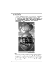
... is Main Panel. c. Main Panel contains fe ature s as follows: a. Display the CPU Speed, CPU external clock, Memory clock, AGP clock, and PCI clock information. Motherboard Manual 2. Please refer to the following figure;
... is Main Panel. c. Main Panel contains fe ature s as follows: a. Display the CPU Speed, CPU external clock, Memory clock, AGP clock, and PCI clock information. Motherboard Manual 2. Please refer to the following figure;

Setup Manual
Page 30
Motherboard Manual 4. O ve rclock Panel contains the these features: a. We strongly recommend you v erify ev ery speed you can just click Auto ov erclock button and let [WarpSpeeder™] automatically gets the best result f or y ou. Or, you overclock by click the Verify button. Warning: Manually overclock is potentially dangerous, especially when the ov...
Motherboard Manual 4. O ve rclock Panel contains the these features: a. We strongly recommend you v erify ev ery speed you can just click Auto ov erclock button and let [WarpSpeeder™] automatically gets the best result f or y ou. Or, you overclock by click the Verify button. Warning: Manually overclock is potentially dangerous, especially when the ov...
Setup Manual
Page 32
Motherboard Manual 6. Note : Because the overclock, overvoltage, and hardware monitor features are related to separate panels. In this panel, you can get the mainboard's BIOS model and ...
Motherboard Manual 6. Note : Because the overclock, overvoltage, and hardware monitor features are related to separate panels. In this panel, you can get the mainboard's BIOS model and ...

Setup Manual
Page 84
...monitor is lost. So, if the AGP driver of the CMOS when AC power is not supplying power, the motherboard uses the motherboard battery (3V). The Choices: Auto (default), Yes, No. "Off" (default) Means always set CMOS to...will need AGP driver to the video buffer. While AC is lost power previously without any subsequent manual intervention. Run VGABIOS if S3 Resume Choosing Enabled will cause the system to turn off the ... enter the Soft-Off state when the system has "hung." K8M800 Micro AM2 BIOS Setup Video Off Method This option determines the manner in MODEM use.
...monitor is lost. So, if the AGP driver of the CMOS when AC power is not supplying power, the motherboard uses the motherboard battery (3V). The Choices: Auto (default), Yes, No. "Off" (default) Means always set CMOS to...will need AGP driver to the video buffer. While AC is lost power previously without any subsequent manual intervention. Run VGABIOS if S3 Resume Choosing Enabled will cause the system to turn off the ... enter the Soft-Off state when the system has "hung." K8M800 Micro AM2 BIOS Setup Video Off Method This option determines the manner in MODEM use.


