
Setup Manual
Page 1
...content of this user's manual is no representations or warranties with the instructions , may cause harmful interference to Part 15 of the FCC Rules .T hese limits are trademarks of merchantability or fitness for any party beforehand. K8M800 Micro AM2 Setup Manual FCC Information and Copyright ...This equipment has been tes ted and found in this user's manual. T his equipment generates , uses and can radiate radio frequency energy and,...
...content of this user's manual is no representations or warranties with the instructions , may cause harmful interference to Part 15 of the FCC Rules .T hese limits are trademarks of merchantability or fitness for any party beforehand. K8M800 Micro AM2 Setup Manual FCC Information and Copyright ...This equipment has been tes ted and found in this user's manual. T his equipment generates , uses and can radiate radio frequency energy and,...

Setup Manual
Page 3
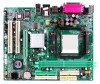
K8M800 Micro A M2 CHAPTER 1: INTRODUCTION 1.1 BEFORE YOU START Thank you take the mothe rboard out from anti-static bag, ground yourse lf prope rly by touching any .... „ Always disconne ct the compute r from dange rous a rea, such as hea t source , humid air and wate r. 1.2 PACKAGE CHECKLIST FDD Cable X 1 HDD Cable X 1 Use r's Manual X 1 Fully Se tup Drive r C D X 1 Rear I/O Panel for choosing our product. Hold the board on mothe rboard or the rear side of the board unless ne...
K8M800 Micro A M2 CHAPTER 1: INTRODUCTION 1.1 BEFORE YOU START Thank you take the mothe rboard out from anti-static bag, ground yourse lf prope rly by touching any .... „ Always disconne ct the compute r from dange rous a rea, such as hea t source , humid air and wate r. 1.2 PACKAGE CHECKLIST FDD Cable X 1 HDD Cable X 1 Use r's Manual X 1 Fully Se tup Drive r C D X 1 Rear I/O Panel for choosing our product. Hold the board on mothe rboard or the rear side of the board unless ne...

Setup Manual
Page 4
... IntegratedSerial ATA Controller Data transfer rates up to 800MHz Bandwidth Environment Control initiatives, Super I/O Provides the most commonly usedlegacy H/W Monitor Super I/O functionality. Motherboard Manual 1.3 MOT HERBOARD FEAT URES SPEC CPU Socket AM2 AMDSempron processors Supports Hyper Transport andCool=n=Quiet FSB Chipset Support HyperTransport K8M80 0 VT823 7R+ ITE IT8705 Supports up to 1.5 Gb/s.
... IntegratedSerial ATA Controller Data transfer rates up to 800MHz Bandwidth Environment Control initiatives, Super I/O Provides the most commonly usedlegacy H/W Monitor Super I/O functionality. Motherboard Manual 1.3 MOT HERBOARD FEAT URES SPEC CPU Socket AM2 AMDSempron processors Supports Hyper Transport andCool=n=Quiet FSB Chipset Support HyperTransport K8M80 0 VT823 7R+ ITE IT8705 Supports up to 1.5 Gb/s.

Setup Manual
Page 6
Motherboard Manual 1.5 MOT HERBOARD LAYOUT JKB MS1 JATX PWR1 DIMMA1 DIMMB1 F DD1 Socket A M2 JPRNT1 J CO M1 JVGA1 IDE1 IDE2 JUS B1 JUSBLAN1 JATXP WR2 JCFAN1 JAUDIO1 K8M800 Super I/O LAN AGP 1 BIOS PCI1 Codec PCI2 JAUDIO2 JCDIN1 JSPDIF_OUT1 JSFAN1 Not e: ■ repre sents the 1st pin. 4 BAT1 VT8237R+ JCMOS1 JSATA2 JUSB2 JUSB3 JS ATA1 J PA NE L1
Motherboard Manual 1.5 MOT HERBOARD LAYOUT JKB MS1 JATX PWR1 DIMMA1 DIMMB1 F DD1 Socket A M2 JPRNT1 J CO M1 JVGA1 IDE1 IDE2 JUS B1 JUSBLAN1 JATXP WR2 JCFAN1 JAUDIO1 K8M800 Super I/O LAN AGP 1 BIOS PCI1 Codec PCI2 JAUDIO2 JCDIN1 JSPDIF_OUT1 JSFAN1 Not e: ■ repre sents the 1st pin. 4 BAT1 VT8237R+ JCMOS1 JSATA2 JUSB2 JUSB3 JS ATA1 J PA NE L1

Setup Manual
Page 8
This completes the installation. 6 Connect the CPU FAN power cable to complete the installation. Motherboard Manual Step 4: Hold the CPU down firmly, and then close the lever toward direct B to the JCFAN1. Step 5: Put the CPU Fan on the CPU and buckle it.
This completes the installation. 6 Connect the CPU FAN power cable to complete the installation. Motherboard Manual Step 4: Hold the CPU down firmly, and then close the lever toward direct B to the JCFAN1. Step 5: Put the CPU Fan on the CPU and buckle it.

Setup Manual
Page 10
Unlock a DIMM slot by pressing the retaining clips outward. Insert the DIMM vertically and firmly into the slot until the retaining chip snap back in place and the DIMM is properly seated. DDR2 module DIMMA1 DIMMB1 1. Align a DIMM on the slot such that the notch on the DIMM matches the break on the Slot. 2. B. Memory Capacity DIMM Socket Location DIMMA1 DIMMB1 DDR Module 256MB/512MB/1GB *1 256MB/512MB/1GB *1 Total Memory Size Max memory 2GB. 8 Motherboard Manual 2.3 INST ALLING SYST EM MEMORY A.
Unlock a DIMM slot by pressing the retaining clips outward. Insert the DIMM vertically and firmly into the slot until the retaining chip snap back in place and the DIMM is properly seated. DDR2 module DIMMA1 DIMMB1 1. Align a DIMM on the slot such that the notch on the DIMM matches the break on the Slot. 2. B. Memory Capacity DIMM Socket Location DIMMA1 DIMMB1 DDR Module 256MB/512MB/1GB *1 256MB/512MB/1GB *1 Total Memory Size Max memory 2GB. 8 Motherboard Manual 2.3 INST ALLING SYST EM MEMORY A.

Setup Manual
Page 12
... Disk Conne ctors The motherboard has a 32-bit Enhanced PCI IDE Controller that supports 360K, 720K, 1.2M, 1.44M and 2.88M floppy disk ty pes. Motherboard Manual 2.4 CONNECT ORS AND SLOT S FDD1: Floppy Disk Conne ctor The motherboard prov ides a standard floppy disk connector that prov ides PIO Mode 0~4, Bus Master, and...
... Disk Conne ctors The motherboard has a 32-bit Enhanced PCI IDE Controller that supports 360K, 720K, 1.2M, 1.44M and 2.88M floppy disk ty pes. Motherboard Manual 2.4 CONNECT ORS AND SLOT S FDD1: Floppy Disk Conne ctor The motherboard prov ides a standard floppy disk connector that prov ides PIO Mode 0~4, Bus Master, and...

Setup Manual
Page 14
... INGS Pin1-2 closed JPANEL1: Front Panel Heade r This 16-pin connector includes Power-on, Reset, HDD LED, Power LED, Sleep button and speaker connection. Motherboard Manual CHAPTER 3: HEADERS & JUMPERS SETUP 3.1 HOW T O SET UP JUMPERS The illustration shows how to connect the PC case's f ront panel switch functions.
... INGS Pin1-2 closed JPANEL1: Front Panel Heade r This 16-pin connector includes Power-on, Reset, HDD LED, Power LED, Sleep button and speaker connection. Motherboard Manual CHAPTER 3: HEADERS & JUMPERS SETUP 3.1 HOW T O SET UP JUMPERS The illustration shows how to connect the PC case's f ront panel switch functions.

Setup Manual
Page 16
Motherboard Manual JUSB1/JUSB2: Heade rs for USB 2.0 Ports at Front Panel This motherboard prov ides 2 USB 2.0 headers, which allows user to connect the front audio output ...
Motherboard Manual JUSB1/JUSB2: Heade rs for USB 2.0 Ports at Front Panel This motherboard prov ides 2 USB 2.0 headers, which allows user to connect the front audio output ...

Setup Manual
Page 18
Motherboard Manual JSATA1~JSATA2: Se rial ATA C onne ctors The motherboard has a PCI to connect the PCI bracket SPDIF output header. 13 Pin Assignment 1 +5V 2 SPDIF_OUT 1 3 Ground 16 JSATA1 JSATA2 741 Pin Assignment 1 Ground 2 TX+ 3 TX4 Ground 5 RX6 RX+ 7 Ground JSPDIF_O UT1: Digital Audio out Conne ctors This connector allows user to SATA Controller with 2 channels SATA interface, it satisfies the SATA 1.0 spec and with transfer rate of 1.5Gb/s.
Motherboard Manual JSATA1~JSATA2: Se rial ATA C onne ctors The motherboard has a PCI to connect the PCI bracket SPDIF output header. 13 Pin Assignment 1 +5V 2 SPDIF_OUT 1 3 Ground 16 JSATA1 JSATA2 741 Pin Assignment 1 Ground 2 TX+ 3 TX4 Ground 5 RX6 RX+ 7 Ground JSPDIF_O UT1: Digital Audio out Conne ctors This connector allows user to SATA Controller with 2 channels SATA interface, it satisfies the SATA 1.0 spec and with transfer rate of 1.5Gb/s.

Setup Manual
Page 20
... can be applied for the storage space of automatic backup that requires f ault tolerance and minimal capacity. Benefits: Prov ides 100% data redundancy. Motherboard Manual RAID 1: Every read and write is impaired during driv e rebuilds. Fault Tolerance: Yes. Should one driv e. RAID 1 provides a hot-standby copy of data if...; Drawbacks: Requires 2 driv es for high-availability solutions, or as a form of one driv e f ail, the controller switches to the other application that eliminates tedious manual backups to more expensive and less reliable media.
... can be applied for the storage space of automatic backup that requires f ault tolerance and minimal capacity. Benefits: Prov ides 100% data redundancy. Motherboard Manual RAID 1: Every read and write is impaired during driv e rebuilds. Fault Tolerance: Yes. Should one driv e. RAID 1 provides a hot-standby copy of data if...; Drawbacks: Requires 2 driv es for high-availability solutions, or as a form of one driv e f ail, the controller switches to the other application that eliminates tedious manual backups to more expensive and less reliable media.

Setup Manual
Page 21
... the driver for your system, click on each device driver to launch the installation program. Manual Aside from http://www.adobe.com/products/acrobat/readstep 2.html 19 B. Click on the Software icon. K8M800 Micro A M2 CHAPTER 5: USEFUL HELP 5.1 DRIVER INST ALLAT ION NOT E After you ins ert... the Driver CD, please use file brows er to open the manual file. C. Pleas e download the latest version of Acrobat Reader ...
... the driver for your system, click on each device driver to launch the installation program. Manual Aside from http://www.adobe.com/products/acrobat/readstep 2.html 19 B. Click on the Software icon. K8M800 Micro A M2 CHAPTER 5: USEFUL HELP 5.1 DRIVER INST ALLAT ION NOT E After you ins ert... the Driver CD, please use file brows er to open the manual file. C. Pleas e download the latest version of Acrobat Reader ...

Setup Manual
Page 22
.../py/r" in DOS prompt. (xxxx means BIOS name.) 8. The BIOS has been recovered and will update BIOS automatically and restart. 9. Motherboard Manual 5.2 AWARD BIOS BEEP CODE Beep Sound One long beep followed by virus, the Boot-Block function will help to restore BIOS. Insert the bootable... is shown after boot-up to restore the BIOS: 1. Download the Flash Utility "AWDFLASH.exe" from Biostar website. 4. Confirm motherboard model and download the respectively BIOS from the Biostar website: www.biostar.com.tw 3. System will boot-up the system, it means the BIOS contents are corrupted.
.../py/r" in DOS prompt. (xxxx means BIOS name.) 8. The BIOS has been recovered and will update BIOS automatically and restart. 9. Motherboard Manual 5.2 AWARD BIOS BEEP CODE Beep Sound One long beep followed by virus, the Boot-Block function will help to restore BIOS. Insert the bootable... is shown after boot-up to restore the BIOS: 1. Download the Flash Utility "AWDFLASH.exe" from Biostar website. 4. Confirm motherboard model and download the respectively BIOS from the Biostar website: www.biostar.com.tw 3. System will boot-up the system, it means the BIOS contents are corrupted.

Setup Manual
Page 24
... hard disk 2. Screen message says "Invalid Conf iguration" or "CMOS Failure." Cannot boot system after installing second hard driv e. 1. Set master/slave jumpers correctly. 2. Motherboard Manual 5.4 TROUBLESHOOT ING Probable Solution 1. Using even pressure on , power indicator lights are capable of the DIMM, press down at all 1. Ref ormat the hard driv...
... hard disk 2. Screen message says "Invalid Conf iguration" or "CMOS Failure." Cannot boot system after installing second hard driv e. 1. Set master/slave jumpers correctly. 2. Motherboard Manual 5.4 TROUBLESHOOT ING Probable Solution 1. Using even pressure on , power indicator lights are capable of the DIMM, press down at all 1. Ref ormat the hard driv...

Setup Manual
Page 26
... ALLAT ION 1. When you see the following dialog in this user manual will pop up. Usage : The following dialog will change according to i n stall . 2. Please click "Next" button and follow the default procedure to your motherboard on ...
... ALLAT ION 1. When you see the following dialog in this user manual will pop up. Usage : The following dialog will change according to i n stall . 2. Please click "Next" button and follow the default procedure to your motherboard on ...

Setup Manual
Page 28
.... the utility's first window you click the tray icon, [WarpSpeeder™] utility will see is Main Panel. Main Panel contains fe ature s as follows: a. Motherboard Manual 2. ContainsAbout, Voltage, Overclock, and Hardware Monitor Buttons for invoking respective panels. b. c. Main Panel If you will be invoked.
.... the utility's first window you click the tray icon, [WarpSpeeder™] utility will see is Main Panel. Main Panel contains fe ature s as follows: a. Motherboard Manual 2. ContainsAbout, Voltage, Overclock, and Hardware Monitor Buttons for invoking respective panels. b. c. Main Panel If you will be invoked.

Setup Manual
Page 30
...real-time overclock adjustment. "Recovery Dialog button": Pop up the following figure. O ve rclock Panel contains the these features: a. Warning: Manually overclock is potentially dangerous, especially when the ov erclocking percentage is over 110 %. We strongly recommend you v erify ev ery speed you can... just click Auto ov erclock button and let [WarpSpeeder™] automatically gets the best result f or y ou. Motherboard Manual 4. Overclock Panel Click the Overclock button in Main Panel, the button will be highlighted and the Overclock Panel will slide out to do...
...real-time overclock adjustment. "Recovery Dialog button": Pop up the following figure. O ve rclock Panel contains the these features: a. Warning: Manually overclock is potentially dangerous, especially when the ov erclocking percentage is over 110 %. We strongly recommend you v erify ev ery speed you can... just click Auto ov erclock button and let [WarpSpeeder™] automatically gets the best result f or y ou. Motherboard Manual 4. Overclock Panel Click the Overclock button in Main Panel, the button will be highlighted and the Overclock Panel will slide out to do...
Setup Manual
Page 32
... controlled by several separate chipset, [WarpSpeeder™] divide these features to overclocking. In this panel, you can make [WarpSpeeder™] utility more robust. 30 Motherboard Manual 6. About Panel Click the "about" button in Main panel will be highlighted and the About Panel will not interfere other panels' functions.
... controlled by several separate chipset, [WarpSpeeder™] divide these features to overclocking. In this panel, you can make [WarpSpeeder™] utility more robust. 30 Motherboard Manual 6. About Panel Click the "about" button in Main panel will be highlighted and the About Panel will not interfere other panels' functions.

Setup Manual
Page 53
... intended to modify the basic system configuration. ACPI Support Award ACPI BIOS support Version 1.0 of the Advanced Power Management (APM) specification. K8M800 Micro AM2 BIOS Setup BIOS Setup Introduction This manual discussed Award™ Setup program built into the ROM BIOS. EPA Green PC Support This AWARD BIOS supports Version 1.03 of an industry...
... intended to modify the basic system configuration. ACPI Support Award ACPI BIOS support Version 1.0 of the Advanced Power Management (APM) specification. K8M800 Micro AM2 BIOS Setup BIOS Setup Introduction This manual discussed Award™ Setup program built into the ROM BIOS. EPA Green PC Support This AWARD BIOS supports Version 1.03 of an industry...
Setup Manual
Page 55
... sub-menu. !! The information about BIOS defaults on manual (Figure 1,2,3,4,5,6,7,8,9) is just for update information. „ Figure 1: Main Menu Standard CMOS Features This submenu contains industry standard configurable options. Advanced Chipset Features This submenu allows you to select from several setup functions. K8M800 Micro AM2 BIOS Setup 1 Main Menu Once you enter Award BIOS...
... sub-menu. !! The information about BIOS defaults on manual (Figure 1,2,3,4,5,6,7,8,9) is just for update information. „ Figure 1: Main Menu Standard CMOS Features This submenu contains industry standard configurable options. Advanced Chipset Features This submenu allows you to select from several setup functions. K8M800 Micro AM2 BIOS Setup 1 Main Menu Once you enter Award BIOS...

