
Setup Manual
Page 1
..., and can radiate radio frequency energy and, if not installed and used in this user's manual is not allowed without obligation to notify any purpose. G31-M7 OC Setup Manual FCC Information and Copyright This equipment has been tested and found in accordance with the limits of a Class B digital device, pursuant to Part...
..., and can radiate radio frequency energy and, if not installed and used in this user's manual is not allowed without obligation to notify any purpose. G31-M7 OC Setup Manual FCC Information and Copyright This equipment has been tested and found in accordance with the limits of a Class B digital device, pursuant to Part...
Setup Manual
Page 3
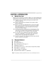
CHAPTER 1: INTRODUCTION G31-M7 OC 1.1 BEFORE YOU START Thank you take the motherboard out from dangerous area, such as heat source, humid air and water. 1.2 PACKAGE CHECKLIST IDE Cable X 1 Serial ...
CHAPTER 1: INTRODUCTION G31-M7 OC 1.1 BEFORE YOU START Thank you take the motherboard out from dangerous area, such as heat source, humid air and water. 1.2 PACKAGE CHECKLIST IDE Cable X 1 Serial ...
Setup Manual
Page 5
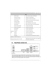
...PS/2 Keyboard PS/2 Mouse Back Panel VGA port I/O LAN port USB Port Audio Jack Board Size 179 (W) x 235 (L) mm OS Support Windows 2000 / XP / VISTA G31-M7 OC SPEC x4 Each connector supports 1 SATA devices x1 Supports front panel facilities x1 Supports front panel audio function x1 CPU Fan power supply (with Smart... x1 Connect to D-SUB monitor x1 Connect to RJ-45 ethernet cable x4 Connect to USB devices x3 Provide Audio-In/Out and microphone connection Biostar Reserves the right to the audio port, please use the Line In (blue) and Mic In (Pink) audio jack. 3 The input / output function ...
...PS/2 Keyboard PS/2 Mouse Back Panel VGA port I/O LAN port USB Port Audio Jack Board Size 179 (W) x 235 (L) mm OS Support Windows 2000 / XP / VISTA G31-M7 OC SPEC x4 Each connector supports 1 SATA devices x1 Supports front panel facilities x1 Supports front panel audio function x1 CPU Fan power supply (with Smart... x1 Connect to D-SUB monitor x1 Connect to RJ-45 ethernet cable x4 Connect to USB devices x3 Provide Audio-In/Out and microphone connection Biostar Reserves the right to the audio port, please use the Line In (blue) and Mic In (Pink) audio jack. 3 The input / output function ...
Setup Manual
Page 7
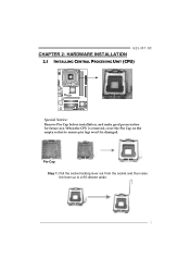
When the CPU is removed, cover the Pin Cap on the empty socket to a 90-degree angle. 5 Pin-Cap Step 1: Pull the socket locking lever out from the socket and then raise the lever up to ensure pin legs won't be damaged. G31-M7 OC CHAPTER 2: HARDWARE INSTALLATION 2.1 INSTALLING CENTRAL PROCESSING UNIT (CPU) Special Notice: Remove Pin Cap before installation, and make good preservation for future use.
When the CPU is removed, cover the Pin Cap on the empty socket to a 90-degree angle. 5 Pin-Cap Step 1: Pull the socket locking lever out from the socket and then raise the lever up to ensure pin legs won't be damaged. G31-M7 OC CHAPTER 2: HARDWARE INSTALLATION 2.1 INSTALLING CENTRAL PROCESSING UNIT (CPU) Special Notice: Remove Pin Cap before installation, and make good preservation for future use.

Setup Manual
Page 9
G31-M7 OC 2.2 FAN HEADERS These fan headers support cooling-fans built in the computer. When connecting with wires onto connectors, please note that the red wire is ...
G31-M7 OC 2.2 FAN HEADERS These fan headers support cooling-fans built in the computer. When connecting with wires onto connectors, please note that the red wire is ...
Setup Manual
Page 11
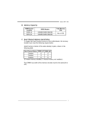
B. Memory Capacity DIMM Socket Location DDR2_A1 DDR2_B1 DDR2 Module 256MB/512MB/1GB/2GB 256MB/512MB/1GB/2GB G31-M7 OC Total Memory Size Max is 4GB. C. Dual Channel Status DDR2_A1 DDR2_B1 Disabled O X Disabled X O Enabled O O (O means memory installed, X means memory not installed.) The DRAM bus width ...
B. Memory Capacity DIMM Socket Location DDR2_A1 DDR2_B1 DDR2 Module 256MB/512MB/1GB/2GB 256MB/512MB/1GB/2GB G31-M7 OC Total Memory Size Max is 4GB. C. Dual Channel Status DDR2_A1 DDR2_B1 Disabled O X Disabled X O Enabled O O (O means memory installed, X means memory not installed.) The DRAM bus width ...
Setup Manual
Page 13
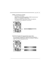
PCI-Express supports a raw bit-rate of 4GB/s simultaneously per direction, for expansion cards. PCI stands for Peripheral Component Interconnect, and it is a bus standard for an aggregate of 8GB/s totally. - PCI-Express 1.0a compliant. - This PCI slot is equipped with 2 standard PCI slots. G31-M7 OC PEX16_1: PCI-Express x16 Slot - Maximum theoretical realized bandwidth of 2.5Gb/s on the data pins. - 2X bandwidth over the traditional PCI architecture. PEX16_1 PCI1/PCI2: Peripheral Component Interconnect Slots This motherboard is designated as 32 bits. PCI1 PCI2 11
PCI-Express supports a raw bit-rate of 4GB/s simultaneously per direction, for expansion cards. PCI stands for Peripheral Component Interconnect, and it is a bus standard for an aggregate of 8GB/s totally. - PCI-Express 1.0a compliant. - This PCI slot is equipped with 2 standard PCI slots. G31-M7 OC PEX16_1: PCI-Express x16 Slot - Maximum theoretical realized bandwidth of 2.5Gb/s on the data pins. - 2X bandwidth over the traditional PCI architecture. PEX16_1 PCI1/PCI2: Peripheral Component Interconnect Slots This motherboard is designated as 32 bits. PCI1 PCI2 11

Setup Manual
Page 15
G31-M7 OC JATXPWR1: ATX Power Source Connector This connector allows user to connect 24-pin power connector on the ATX power supply. 12 24 1 13 Pin Assignment ...
G31-M7 OC JATXPWR1: ATX Power Source Connector This connector allows user to connect 24-pin power connector on the ATX power supply. 12 24 1 13 Pin Assignment ...

Setup Manual
Page 17
... to "Pin 1-2 close ". 3. Set the jumper to avoid damaging the motherboard. 3 1 Pin 1-2 Close: Normal Operation (Default). 3 1 3 1 Pin 2-3 Close: Clear CMOS data. ※ Clear CMOS Procedures: 1. G31-M7 OC JCMOS1: Clear CMOS Header By placing the jumper on the AC. 6. SATA1~SATA4: Serial ATA Connectors The motherboard has a PCI to SATA Controller with transfer...
... to "Pin 1-2 close ". 3. Set the jumper to avoid damaging the motherboard. 3 1 Pin 1-2 Close: Normal Operation (Default). 3 1 3 1 Pin 2-3 Close: Clear CMOS data. ※ Clear CMOS Procedures: 1. G31-M7 OC JCMOS1: Clear CMOS Header By placing the jumper on the AC. 6. SATA1~SATA4: Serial ATA Connectors The motherboard has a PCI to SATA Controller with transfer...

Setup Manual
Page 19
G31-M7 OC 2 1 Pin Assignment 1 -Strobe 2 -ALF 3 Data 0 4 -Error 5 Data 1 6 -Init 7 Data 2 8 -Scltin 9 Data 3 10 Ground 11 Data 4 12 Ground 13 Data 5 25 Pin Assignment 14 Ground 15 Data 6 16 Ground 17 Data 7 18 Ground 19 -ACK 20 Ground 21 Busy 22 Ground 23 PE 24 Ground 25 SCLT 26 Key 17 JPRNT1: Printer Port Connector This header allows you to connector printer on the PC.
G31-M7 OC 2 1 Pin Assignment 1 -Strobe 2 -ALF 3 Data 0 4 -Error 5 Data 1 6 -Init 7 Data 2 8 -Scltin 9 Data 3 10 Ground 11 Data 4 12 Ground 13 Data 5 25 Pin Assignment 14 Ground 15 Data 6 16 Ground 17 Data 7 18 Ground 19 -ACK 20 Ground 21 Busy 22 Ground 23 PE 24 Ground 25 SCLT 26 Key 17 JPRNT1: Printer Port Connector This header allows you to connector printer on the PC.
Setup Manual
Page 21
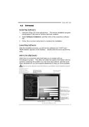
... collect the system information which would be able to complete the installation. Save these information to our tech-support department to the optical drive. 4.2 SOFTWARE G31-M7 OC Installing Software 1. Provide the name of the memor y module manufacturer. Send the mail out. This utility will show the i nformation which is a convenient utility that...
... collect the system information which would be able to complete the installation. Save these information to our tech-support department to the optical drive. 4.2 SOFTWARE G31-M7 OC Installing Software 1. Provide the name of the memor y module manufacturer. Send the mail out. This utility will show the i nformation which is a convenient utility that...
Setup Manual
Page 23
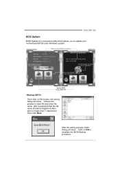
... Clear CMOS function (Only for AWARD BIOS) Online Update function (Only for AMI BIOS) Save current BIOS to update your motherboard BIOS under Windows system. G31-M7 OC BIOS Update BIOS Update is a convenient utility which allows you to a .bin file Update BIOS with a BIOS file Once click on OK to save file...
... Clear CMOS function (Only for AWARD BIOS) Online Update function (Only for AMI BIOS) Save current BIOS to update your motherboard BIOS under Windows system. G31-M7 OC BIOS Update BIOS Update is a convenient utility which allows you to a .bin file Update BIOS with a BIOS file Once click on OK to save file...

Setup Manual
Page 25
... OK to reboot the system. The actual information and settings on the Online Update button, the utility will also tell you to reboot. Download completes; G31-M7 OC (for the latest BIOS from this function.
... OK to reboot the system. The actual information and settings on the Online Update button, the utility will also tell you to reboot. Download completes; G31-M7 OC (for the latest BIOS from this function.
Setup Manual
Page 27
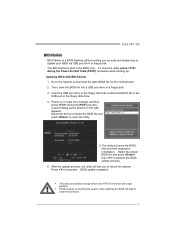
... picture on or reset the computer and then press during the Power-On Self Tests (POST) procedure while booting up. Press to enter the utility. 5. G31-M7 OC BIO-Flasher BIO-Flasher is built in the BIOS chip. Select the device contains the BIOS file and press to proceed. Power on the right...
... picture on or reset the computer and then press during the Power-On Self Tests (POST) procedure while booting up. Press to enter the utility. 5. G31-M7 OC BIO-Flasher BIO-Flasher is built in the BIOS chip. Select the device contains the BIOS file and press to proceed. Power on the right...

Setup Manual
Page 29
... standard CMOS setup. 2. Make sure correct information is extremely important. drive, can be booted from optical drive. 1. Cannot boot system after installing second hard drive. 1. G31-M7 OC 4.5 TROUBLESHOOTING Probable Solution 1. Replace cable. System inoperative. Run SETUP program and select correct drive types. on both ends are lit, and hard drive is spinning...
... standard CMOS setup. 2. Make sure correct information is extremely important. drive, can be booted from optical drive. 1. Cannot boot system after installing second hard drive. 1. G31-M7 OC 4.5 TROUBLESHOOTING Probable Solution 1. Replace cable. System inoperative. Run SETUP program and select correct drive types. on both ends are lit, and hard drive is spinning...