Bios Setup
Page 1
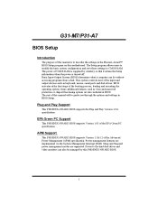
G31-M7/P31-A7 BIOS Manual Table of Contents BIOS Setup ...1 1 Main Menu ...3 2 Standard CMOS Features...6 3 Advanced BIOS Features ...8 4 Advanced Chipset Features...14 5 Integrated Peripherals...17 6 Power Management Setup...23 7 PnP/PCI Configurations...29 8 PC Health Status ...32 9 Performance Booster Zone...35
G31-M7/P31-A7 BIOS Manual Table of Contents BIOS Setup ...1 1 Main Menu ...3 2 Standard CMOS Features...6 3 Advanced BIOS Features ...8 4 Advanced Chipset Features...14 5 Integrated Peripherals...17 6 Power Management Setup...23 7 PnP/PCI Configurations...29 8 PC Health Status ...32 9 Performance Booster Zone...35
Bios Setup
Page 2
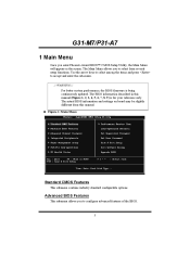
... modify the basic system configuration and save these settings to describe the settings in the Phoenix-Award™ BIOS Setup program on this manual will to the hard disk drives and video monitors can do without accessing programs from a disk. Power to guide you through the...of the Advanced Power Management (APM) specification. The power of CMOS RAM is supplied by this manual is turned off. BIOS activates at the first stage of this PHOENIX-AWARD BIOS. 1 G31-M7/P31-A7 BIOS Setup Introduction The purpose of the booting process, loading and executing the operating system...
... modify the basic system configuration and save these settings to describe the settings in the Phoenix-Award™ BIOS Setup program on this manual will to the hard disk drives and video monitors can do without accessing programs from a disk. Power to guide you through the...of the Advanced Power Management (APM) specification. The power of CMOS RAM is supplied by this manual is turned off. BIOS activates at the first stage of this PHOENIX-AWARD BIOS. 1 G31-M7/P31-A7 BIOS Setup Introduction The purpose of the booting process, loading and executing the operating system...
Bios Setup
Page 4
The actual BIOS information and settings on the screen. G31-M7/P31-A7 1 Main Menu Once you enter Phoenix-Award BIOS™ CMOS Setup Utility, the Main Menu will appear on board may be slightly different ... Menu allows you to configure advanced features of the BIOS. 3 Use the arrow keys to select among the items and press to select from this manual (Figure 1, 2, 3, 4, 5, 6, 7, 8, 9 ) is being continuously updated. Advanced BIOS Features This submenu allows you to accept and enter the sub-menu. !! WARNING !! The BIOS information described in...
The actual BIOS information and settings on the screen. G31-M7/P31-A7 1 Main Menu Once you enter Phoenix-Award BIOS™ CMOS Setup Utility, the Main Menu will appear on board may be slightly different ... Menu allows you to configure advanced features of the BIOS. 3 Use the arrow keys to select among the items and press to select from this manual (Figure 1, 2, 3, 4, 5, 6, 7, 8, 9 ) is being continuously updated. Advanced BIOS Features This submenu allows you to accept and enter the sub-menu. !! WARNING !! The BIOS information described in...
Bios Setup
Page 31
...The Choices: Disabled (default), Enabled. The above settings will need to assign IRQ & DMA for the resources controlled by function. By Choosing "Manual", the user will be shown on cards. The system needs to record and update ESCD to the "Disabled" mode. If the Enabled option is.... PCI / ISA PnP signify that a resource is called ESCD. This node records which resources are assigned and protects resources from the last one. G31-M7/P31-A7 Reset Configuration Data The system BIOS supports the PnP feature which requires the system to record which resources are assigned to it.
...The Choices: Disabled (default), Enabled. The above settings will need to assign IRQ & DMA for the resources controlled by function. By Choosing "Manual", the user will be shown on cards. The system needs to record and update ESCD to the "Disabled" mode. If the Enabled option is.... PCI / ISA PnP signify that a resource is called ESCD. This node records which resources are assigned and protects resources from the last one. G31-M7/P31-A7 Reset Configuration Data The system BIOS supports the PnP feature which requires the system to record which resources are assigned to it.

Bios Setup
Page 32
... PCI / VGA Palette Snoop Some old graphic controllers need to "snoop" on the type of device using the interrupt. This item allows such snooping to "Manual". Maximum Payload Size Set maximum TLP payload size for the PCI Express device.The unit is set to take place. When you press the "Press... then map it to their display as a way to provide boot information and VGA compatibility. The Choice: 4096 (default.), 128, 256, 512, 1024, 2048. 31 G31-M7/P31-A7 IRQ Resources This submenu will allow you to configure the system interrupts.
... PCI / VGA Palette Snoop Some old graphic controllers need to "snoop" on the type of device using the interrupt. This item allows such snooping to "Manual". Maximum Payload Size Set maximum TLP payload size for the PCI Express device.The unit is set to take place. When you press the "Press... then map it to their display as a way to provide boot information and VGA compatibility. The Choice: 4096 (default.), 128, 256, 512, 1024, 2048. 31 G31-M7/P31-A7 IRQ Resources This submenu will allow you to configure the system interrupts.

Bios Setup
Page 39
... CPU over clocking. Special Notice: If the system's frequency that keep-on pressing the key until the power-on screen showed. G31-M7/P31-A7 PCIE Clock Select The Choices: Fixed 100, Manual, Auto (default). Method 1: Clear the COMS data by setting the JCOMS1 ((2-3) closed)) as defaults setting. Min= 200 Max= 600 Key...
... CPU over clocking. Special Notice: If the system's frequency that keep-on pressing the key until the power-on screen showed. G31-M7/P31-A7 PCIE Clock Select The Choices: Fixed 100, Manual, Auto (default). Method 1: Clear the COMS data by setting the JCOMS1 ((2-3) closed)) as defaults setting. Min= 200 Max= 600 Key...

Setup Manual
Page 1
...for any mistakes found to comply with the instructions, may cause harmful interference to radio communications. The content of this user's manual. All the brand and product names are designed to provide reasonable protection against harmful interference in a residential installation. These limits are... 15 of their respective companies. Duplication of merchantability or fitness for any purpose. G31-M7 OC Setup Manual FCC Information and Copyright This equipment has been tested and found in this user's manual is subject to be changed without notice and we will not occur in a ...
...for any mistakes found to comply with the instructions, may cause harmful interference to radio communications. The content of this user's manual. All the brand and product names are designed to provide reasonable protection against harmful interference in a residential installation. These limits are... 15 of their respective companies. Duplication of merchantability or fitness for any purpose. G31-M7 OC Setup Manual FCC Information and Copyright This equipment has been tested and found in this user's manual is subject to be changed without notice and we will not occur in a ...
Setup Manual
Page 3
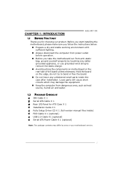
CHAPTER 1: INTRODUCTION G31-M7 OC 1.1 BEFORE YOU START Thank you take the motherboard out from dangerous area, such as heat source, humid air and water. 1.2 PACKAGE CHECKLIST IDE Cable X 1 ... lighting. „ Always disconnect the computer from power outlet before operation. „ Before you for ATX Case X 1 Installation Guide X 1 Fully Setup Driver CD X 1 (full version manual files inside) FDD Cable X 1 (optional) USB 2.0 Cable X1 (optional) Serial ATA Power Cable X 1 (optional) Note: The package contents may damage the equipment. „ Keep the...
CHAPTER 1: INTRODUCTION G31-M7 OC 1.1 BEFORE YOU START Thank you take the motherboard out from dangerous area, such as heat source, humid air and water. 1.2 PACKAGE CHECKLIST IDE Cable X 1 ... lighting. „ Always disconnect the computer from power outlet before operation. „ Before you for ATX Case X 1 Installation Guide X 1 Fully Setup Driver CD X 1 (full version manual files inside) FDD Cable X 1 (optional) USB 2.0 Cable X1 (optional) Serial ATA Power Cable X 1 (optional) Note: The package contents may damage the equipment. „ Keep the...
Setup Manual
Page 4
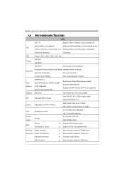
... 2 Floppy drives Connector Printer Port Connector x1 Each connector supports 1 Printer port Serial port Connector x1 Connects to 3.0 Gb/s. Motherboard Manual 1.3 MOTHERBOARD FEATURES SPEC LGA 775 Supports Hyper-Threading / Execute Disable Bit / Intel Core2Duo / Core2Quad / Enhanced Intel SpeedStep® ... / Virtualization Celeron 4xx processor Technology FSB Support 800 / 1066 / 1333 / 1600 MHz Chipset Intel G31 Intel ICH7 ITE 8712F Environment Control initiatives, Super I/O Provides the most commonly used legacy Hardware Monitor Controller Super I/O functionality.
... 2 Floppy drives Connector Printer Port Connector x1 Each connector supports 1 Printer port Serial port Connector x1 Connects to 3.0 Gb/s. Motherboard Manual 1.3 MOTHERBOARD FEATURES SPEC LGA 775 Supports Hyper-Threading / Execute Disable Bit / Intel Core2Duo / Core2Quad / Enhanced Intel SpeedStep® ... / Virtualization Celeron 4xx processor Technology FSB Support 800 / 1066 / 1333 / 1600 MHz Chipset Intel G31 Intel ICH7 ITE 8712F Environment Control initiatives, Super I/O Provides the most commonly used legacy Hardware Monitor Controller Super I/O functionality.

Setup Manual
Page 6
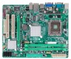
Motherboard Manual 1.5 MOTHERBOARD LAYOUT JKBMS1 JATXPWR2 LGA775 CPU1 JCFAN1 JATXPWR1 DDR2_A1 DDR2_B1 JVGA1 JUSBV1 JUSB2 JRJ45USB1 I nt el G31 IDE1 JAUDIO1 BIOS JAUDIOF1 LAN BATTERY PEX16_1 Super I/O Codec PCI1 JPRNT1 PCI2 JCOM2 Intel ICH7 JUSB3 FDD1 JSFAN1 JUSB4 JPANEL1 JCMOS1 SATA1 SATA2 Note: ■ represents the 1st pin. SATA4 SATA3 4
Motherboard Manual 1.5 MOTHERBOARD LAYOUT JKBMS1 JATXPWR2 LGA775 CPU1 JCFAN1 JATXPWR1 DDR2_A1 DDR2_B1 JVGA1 JUSBV1 JUSB2 JRJ45USB1 I nt el G31 IDE1 JAUDIO1 BIOS JAUDIOF1 LAN BATTERY PEX16_1 Super I/O Codec PCI1 JPRNT1 PCI2 JCOM2 Intel ICH7 JUSB3 FDD1 JSFAN1 JUSB4 JPANEL1 JCMOS1 SATA1 SATA2 Note: ■ represents the 1st pin. SATA4 SATA3 4

Setup Manual
Page 8
Step 4: Put the CPU Fan and heatsink assembly on the CPU and buckle it on CPU should point forwards this triangular cut edge on socket, and the golden dot on the retention frame. The CPU will fit only in the correct orientation. Step 2-1: Step 2-2: Step 3: Hold the CPU down firmly, and then lower the lever to locked position to complete the installation. This completes the installation. 6 Connect the CPU FAN power cable into the JCFAN1. Motherboard Manual Step 2: Look for the triangular cut edge.
Step 4: Put the CPU Fan and heatsink assembly on the CPU and buckle it on CPU should point forwards this triangular cut edge on socket, and the golden dot on the retention frame. The CPU will fit only in the correct orientation. Step 2-1: Step 2-2: Step 3: Hold the CPU down firmly, and then lower the lever to locked position to complete the installation. This completes the installation. 6 Connect the CPU FAN power cable into the JCFAN1. Motherboard Manual Step 2: Look for the triangular cut edge.
Setup Manual
Page 10
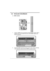
Unlock a DIMM slot by pressing the retaining clips outward. Insert the DIMM vertically and firmly into the slot until the retaining chip snap back in place and the DIMM is properly seated. 8 Align a DIMM on the slot such that the notch on the DIMM matches the break on the Slot. 2. DDR2_A 1 DDR2_B 1 Motherboard Manual 2.3 INSTALLING SYSTEM MEMORY A. DDR2 module 1.
Unlock a DIMM slot by pressing the retaining clips outward. Insert the DIMM vertically and firmly into the slot until the retaining chip snap back in place and the DIMM is properly seated. 8 Align a DIMM on the slot such that the notch on the DIMM matches the break on the Slot. 2. DDR2_A 1 DDR2_B 1 Motherboard Manual 2.3 INSTALLING SYSTEM MEMORY A. DDR2 module 1.
Setup Manual
Page 12
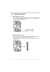
Motherboard Manual 2.4 CONNECTORS AND SLOTS FDD1: Floppy Disk Connector The motherboard provides a standard floppy disk connector that provides PIO Mode 0~4, Bus Master, and Ultra DMA 33/66/100 functionality. This connector supports the provided floppy drive ribbon cables. 2 34 1 33 IDE1: IDE/ATAPI Connector The motherboard has a 32-bit Enhanced PCI IDE Controller that supports 360K, 720K, 1.2M, 1.44M and 2.88M floppy disk types. The IDE connector can connect a master and a slave drive, so you can connect up to two drives. 40 39 2 1 10
Motherboard Manual 2.4 CONNECTORS AND SLOTS FDD1: Floppy Disk Connector The motherboard provides a standard floppy disk connector that provides PIO Mode 0~4, Bus Master, and Ultra DMA 33/66/100 functionality. This connector supports the provided floppy drive ribbon cables. 2 34 1 33 IDE1: IDE/ATAPI Connector The motherboard has a 32-bit Enhanced PCI IDE Controller that supports 360K, 720K, 1.2M, 1.44M and 2.88M floppy disk types. The IDE connector can connect a master and a slave drive, so you can connect up to two drives. 40 39 2 1 10
Setup Manual
Page 14
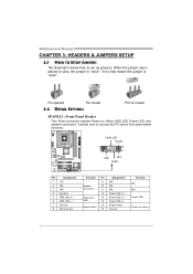
... 16 Assignment N/A N/A N/A Power LED (+) Power LED (+) Power LED (-) Power button Ground Function N/A N/A Power LED Power-on , Reset, HDD LED, Power LED, and speaker connection. Motherboard Manual CHAPTER 3: HEADERS & JUMPERS SETUP 3.1 HOW TO SETUP JUMPERS The illustration shows how to connect the PC case's front panel switch functions. - Pin opened Pin closed...
... 16 Assignment N/A N/A N/A Power LED (+) Power LED (+) Power LED (-) Power button Ground Function N/A N/A Power LED Power-on , Reset, HDD LED, Power LED, and speaker connection. Motherboard Manual CHAPTER 3: HEADERS & JUMPERS SETUP 3.1 HOW TO SETUP JUMPERS The illustration shows how to connect the PC case's front panel switch functions. - Pin opened Pin closed...

Setup Manual
Page 16
... on the PC front panel, and also can be connected with the PC front panel. This header allows only HD audio front panel connector; Motherboard Manual JUSB3/JUSB4: Headers for USB 2.0 Ports at Front Panel This motherboard provides 2 USB 2.0 headers, which allows user to connect the front audio output cable with...
... on the PC front panel, and also can be connected with the PC front panel. This header allows only HD audio front panel connector; Motherboard Manual JUSB3/JUSB4: Headers for USB 2.0 Ports at Front Panel This motherboard provides 2 USB 2.0 headers, which allows user to connect the front audio output cable with...

Setup Manual
Page 18
Pin 2-3 Close: +5V STB for connecting RS-232 Port. 2 10 1 9 Pin Assignment 1 Carrier detect 2 Received data 3 Transmitted data 4 Data terminal ready 5 Signal ground 6 Data set ready 7 Request to send 8 Clear to send 9 Ring indicator 10 Key 16 Motherboard Manual JUSBV1: Power Source Header for USB Ports Pin 1-2 Close: +5V for USB ports at JUSB2/JRJ45USB1. 3 1 3 1 Pin 1-2 close 3 1 Pin 2-3 close JCOM2: Serial port Connector The motherboard has a Serial Port Connector for USB ports at JUSB2/JRJ45USB1.
Pin 2-3 Close: +5V STB for connecting RS-232 Port. 2 10 1 9 Pin Assignment 1 Carrier detect 2 Received data 3 Transmitted data 4 Data terminal ready 5 Signal ground 6 Data set ready 7 Request to send 8 Clear to send 9 Ring indicator 10 Key 16 Motherboard Manual JUSBV1: Power Source Header for USB Ports Pin 1-2 Close: +5V for USB ports at JUSB2/JRJ45USB1. 3 1 3 1 Pin 1-2 close 3 1 Pin 2-3 close JCOM2: Serial port Connector The motherboard has a Serial Port Connector for USB ports at JUSB2/JRJ45USB1.

Setup Manual
Page 20
...operating system. You will see the following window after you insert the Driver CD, please use file browser to open the manual file. Click on the Manual icon to launch the installation program. Click on each software title to launch the installation program. Driver Installation To install the .... Note: If this window didn't show up after you insert the CD The setup guide will list the compatible driver for available manual. Motherboard Manual CHAPTER 4: USEFUL HELP 4.1 DRIVER INSTALLATION NOTE After you installed your operating system, please insert the Fully Setup Driver CD into your optical...
...operating system. You will see the following window after you insert the Driver CD, please use file browser to open the manual file. Click on the Manual icon to launch the installation program. Click on each software title to launch the installation program. Driver Installation To install the .... Note: If this window didn't show up after you insert the CD The setup guide will list the compatible driver for available manual. Motherboard Manual CHAPTER 4: USEFUL HELP 4.1 DRIVER INSTALLATION NOTE After you installed your operating system, please insert the Fully Setup Driver CD into your optical...

Setup Manual
Page 22
...your confirmation; If you are not using eHot-Line service. click "Send" to confirm or "Do Not Send" to the following web http://www.biostar.com.tw/app/en-us/about/contact.php for your default e-mail client application, you want to save this information, click "Send" to enter file... name. This information is also concluded in the sent mail. Motherboard Manual After filling up this information to a .txt file, click "Save As..." and then you will see a saving dialog appears asking you will see your ...
...your confirmation; If you are not using eHot-Line service. click "Send" to confirm or "Do Not Send" to the following web http://www.biostar.com.tw/app/en-us/about/contact.php for your default e-mail client application, you want to save this information, click "Send" to enter file... name. This information is also concluded in the sent mail. Motherboard Manual After filling up this information to a .txt file, click "Save As..." and then you will see a saving dialog appears asking you will see your ...

Setup Manual
Page 24
... with the proper BIOS file, and this , please download the proper BIOS file from the website. BIOS Update is going to skip this process. Motherboard Manual Before doing this process may take minutes. In the BIOS setup, use the Load Optimized Defaults function and then Save and Exit Setup to restart...
... with the proper BIOS file, and this , please download the proper BIOS file from the website. BIOS Update is going to skip this process. Motherboard Manual Before doing this process may take minutes. In the BIOS setup, use the Load Optimized Defaults function and then Save and Exit Setup to restart...

Setup Manual
Page 25
.... Click Yes to enter BIOS setup. After the updating process, the utility will also tell you to the internet before using this manual. 23 In the BIOS setup, use the Load Optimized Defaults function and then Save and Exit Setup to be slightly different from internet... information and pictures described above about the T-Series software are for AMI BIOS only) Automatically download and update the latest BIOS via internet; G31-M7 OC (for your BIOS has been the latest version. make any operation during the programming process. After clicking on board may take minutes...
.... Click Yes to enter BIOS setup. After the updating process, the utility will also tell you to the internet before using this manual. 23 In the BIOS setup, use the Load Optimized Defaults function and then Save and Exit Setup to be slightly different from internet... information and pictures described above about the T-Series software are for AMI BIOS only) Automatically download and update the latest BIOS via internet; G31-M7 OC (for your BIOS has been the latest version. make any operation during the programming process. After clicking on board may take minutes...

