Setup Manual
Page 2
Table of Contents Chapter 1: Introduction 1 1.1 Before You Start 1 1.2 Package Checklist 1 1.3 Motherboard Features 2 1.4 Rear Panel Connectors 3 1.5 Motherboard Layout 4 Chapter 2: Hardware Installation 5 2.1 Installing Central Processing Unit (CPU 5 2.2 FAN Headers 7 2.3 Installing System Memory 8 2.4 Connectors and Slots 10 Chapter 3: Headers & Jumpers Setup 12 3.1 How to ...
Table of Contents Chapter 1: Introduction 1 1.1 Before You Start 1 1.2 Package Checklist 1 1.3 Motherboard Features 2 1.4 Rear Panel Connectors 3 1.5 Motherboard Layout 4 Chapter 2: Hardware Installation 5 2.1 Installing Central Processing Unit (CPU 5 2.2 FAN Headers 7 2.3 Installing System Memory 8 2.4 Connectors and Slots 10 Chapter 3: Headers & Jumpers Setup 12 3.1 How to ...
Setup Manual
Page 3
CHAPTER 1: INTRODUCTION 945GC-M7 TE 1.1 BEFORE YOU START Thank you take the motherboard out from dangerous area, such as heat source, humid air and water. 1.2 PACKAGE CHECKLIST HDD Cable X 1 Rear I/O Panel for choosing our product. Loose parts will ... which may differ by touching any safely grounded appliance, or use grounded wrist strap to remove the static charge. „ Avoid touching the components on motherboard or the rear side of the board unless necessary. Hold the board on the edge, do not try to bend or flex the board. „...
CHAPTER 1: INTRODUCTION 945GC-M7 TE 1.1 BEFORE YOU START Thank you take the motherboard out from dangerous area, such as heat source, humid air and water. 1.2 PACKAGE CHECKLIST HDD Cable X 1 Rear I/O Panel for choosing our product. Loose parts will ... which may differ by touching any safely grounded appliance, or use grounded wrist strap to remove the static charge. „ Avoid touching the components on motherboard or the rear side of the board unless necessary. Hold the board on the edge, do not try to bend or flex the board. „...
Setup Manual
Page 4
... SATA Connector x4 Each connector supports 1 SATA devices 2 FSB 533 / 800 / 1066 / 1333 MHz Chipset Intel 945GC Intel ICH7 Graphics Intel GMA 950 Max Shared Video Memory is recommended to 3.0 Gb/s. SATA Version 2.0 specification compliant. Motherboard Manual 1.3 MOTHERBOARD FEATURES SPEC LGA 775 Supports Hyper-Threading Intel Core2Duo / Pentium 4 / Pentium D / Execute Disable Bit CPU...
... SATA Connector x4 Each connector supports 1 SATA devices 2 FSB 533 / 800 / 1066 / 1333 MHz Chipset Intel 945GC Intel ICH7 Graphics Intel GMA 950 Max Shared Video Memory is recommended to 3.0 Gb/s. SATA Version 2.0 specification compliant. Motherboard Manual 1.3 MOTHERBOARD FEATURES SPEC LGA 775 Supports Hyper-Threading Intel Core2Duo / Pentium 4 / Pentium D / Execute Disable Bit CPU...

Setup Manual
Page 6
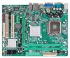
Motherboard Manual 1.5 MOTHERBOARD LAYOUT JKBMS1 LGA775 COJMC1OM1 CPU1 JATXPWR2 JCFAN1 JATXPWR1 JVGA1 DDR2_A1 DDR2_B1 IDE1 JUSB2 JUSBV1 JRJ45USB1 JAUDIO1 Intel 945GC DVIJ1(Optional) PEX16_1 JSFAN1 LAN JCDIN1 Codec JAUDIOF1 PEX1_1 BAT1 BIOS JCMOS1 PCI1 JSPDIF_OUT1 PCI2 JPRNT1 FDD1 Intel ICH7 JUSBV2 JUSB3 JUSB4 Note: ■ represents the 1st pin. 4 SATA2 SATA3 SATA4 SATA1 JPANEL1
Motherboard Manual 1.5 MOTHERBOARD LAYOUT JKBMS1 LGA775 COJMC1OM1 CPU1 JATXPWR2 JCFAN1 JATXPWR1 JVGA1 DDR2_A1 DDR2_B1 IDE1 JUSB2 JUSBV1 JRJ45USB1 JAUDIO1 Intel 945GC DVIJ1(Optional) PEX16_1 JSFAN1 LAN JCDIN1 Codec JAUDIOF1 PEX1_1 BAT1 BIOS JCMOS1 PCI1 JSPDIF_OUT1 PCI2 JPRNT1 FDD1 Intel ICH7 JUSBV2 JUSB3 JUSB4 Note: ■ represents the 1st pin. 4 SATA2 SATA3 SATA4 SATA1 JPANEL1

Setup Manual
Page 8
Motherboard Manual Step 2: Look for the triangular cut edge. This completes the installation. 6 Step 2-1: Step 2-2: Step 3: Hold the CPU down firmly, and then lower the lever to locked position to complete the installation. Connect the CPU FAN power cable into the JCFAN1. Step 4: Put the CPU Fan and heatsink assembly on the CPU and buckle it on CPU should point forwards this triangular cut edge on socket, and the golden dot on the retention frame. The CPU will fit only in the correct orientation.
Motherboard Manual Step 2: Look for the triangular cut edge. This completes the installation. 6 Step 2-1: Step 2-2: Step 3: Hold the CPU down firmly, and then lower the lever to locked position to complete the installation. Connect the CPU FAN power cable into the JCFAN1. Step 4: Put the CPU Fan and heatsink assembly on the CPU and buckle it on CPU should point forwards this triangular cut edge on socket, and the golden dot on the retention frame. The CPU will fit only in the correct orientation.

Setup Manual
Page 10
DDR2 Module 1. Insert the DIMM vertically and firmly into the slot until the retaining chip snap back in place and the DIMM is properly seated. 8 Unlock a DIMM slot by pressing the retaining clips outward. Align a DIMM on the slot such that the notch on the DIMM matches the break on the Slot. 2. DDR2_A1 DDR2_B1 Motherboard Manual 2.3 INSTALLING SYSTEM MEMORY A.
DDR2 Module 1. Insert the DIMM vertically and firmly into the slot until the retaining chip snap back in place and the DIMM is properly seated. 8 Unlock a DIMM slot by pressing the retaining clips outward. Align a DIMM on the slot such that the notch on the DIMM matches the break on the Slot. 2. DDR2_A1 DDR2_B1 Motherboard Manual 2.3 INSTALLING SYSTEM MEMORY A.

Setup Manual
Page 11
...installed CPU. Please refer to the table below to the FSB frequency of the installed CPU, the motherboard could support DDR2 400/533/667 modules. Dual Channel Status DDR2_A1 DDR2_B1 Disabled O X Disabled X....) The DRAM bus width of the memory module must meet the following requirements: Install memory module of the motherboard, the memory module must be the same (x8 or x16) D. C. Dual Channel Memory Installation To trigger...Memory Capacity DIMM Socket Location DDR2_A1 DDR2_B1 DDR2 Module 256MB/512MB/1GB *1 256MB/512MB/1GB *1 945GC-M7 TE Total Memory Size Max memory 2GB.
...installed CPU. Please refer to the table below to the FSB frequency of the installed CPU, the motherboard could support DDR2 400/533/667 modules. Dual Channel Status DDR2_A1 DDR2_B1 Disabled O X Disabled X....) The DRAM bus width of the memory module must meet the following requirements: Install memory module of the motherboard, the memory module must be the same (x8 or x16) D. C. Dual Channel Memory Installation To trigger...Memory Capacity DIMM Socket Location DDR2_A1 DDR2_B1 DDR2 Module 256MB/512MB/1GB *1 256MB/512MB/1GB *1 945GC-M7 TE Total Memory Size Max memory 2GB.

Setup Manual
Page 12
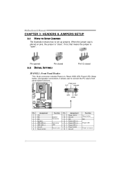
This connector supports the provided floppy drive ribbon cables. 33 1 34 2 IDE1: Hard Disk Connectors The motherboard has a 32-bit Enhanced PCI IDE Controller that supports 360K, 720K, 1.2M, 1.44M and 2.88M floppy disk types. The IDE connector can connect a master and a slave drive, so you can connect up to two hard disk drives. 40 39 2 1 10 Motherboard Manual 2.4 CONNECTORS AND SLOTS FDD1: Floppy Disk Connector The motherboard provides a standard floppy disk connector that provides PIO Mode 0~4, Bus Master, and Ultra DMA 33/66/100 functionality.
This connector supports the provided floppy drive ribbon cables. 33 1 34 2 IDE1: Hard Disk Connectors The motherboard has a 32-bit Enhanced PCI IDE Controller that supports 360K, 720K, 1.2M, 1.44M and 2.88M floppy disk types. The IDE connector can connect a master and a slave drive, so you can connect up to two hard disk drives. 40 39 2 1 10 Motherboard Manual 2.4 CONNECTORS AND SLOTS FDD1: Floppy Disk Connector The motherboard provides a standard floppy disk connector that provides PIO Mode 0~4, Bus Master, and Ultra DMA 33/66/100 functionality.

Setup Manual
Page 13
PCI-Express 1.0a compliant. - PCI-Express supports a raw bit-rate of 8GB/s totally. PEX16_1 PEX1_1 PCI1~PCI2: Peripheral Component Interconnect Slots The motherboard is designated as 32 bits. PCI1 PCI2 11 PCI-Express 1.0a compliant. - This PCI slot is equipped with 2 standard PCI slots. PEX1_1: PCI-Express... Component Interconnect, and it is a bus standard for an aggregate of 2.5Gb/s on the data pins. - 2X bandwidth over the traditional PCI architecture. 945GC-M7 TE PEX16_1: PCI-Express x16 Slot - Data transfer bandwidth up to 250MB/s per direction, for expansion cards.
PCI-Express 1.0a compliant. - PCI-Express supports a raw bit-rate of 8GB/s totally. PEX16_1 PEX1_1 PCI1~PCI2: Peripheral Component Interconnect Slots The motherboard is designated as 32 bits. PCI1 PCI2 11 PCI-Express 1.0a compliant. - This PCI slot is equipped with 2 standard PCI slots. PEX1_1: PCI-Express... Component Interconnect, and it is a bus standard for an aggregate of 2.5Gb/s on the data pins. - 2X bandwidth over the traditional PCI architecture. 945GC-M7 TE PEX16_1: PCI-Express x16 Slot - Data transfer bandwidth up to 250MB/s per direction, for expansion cards.
Setup Manual
Page 14
.... PWR_LED SLP ON/OFF ++- 9 16 1 8 +- When the jumper cap is placed on pins, the jumper is "close", if not, that means the jumper is "open". Motherboard Manual CHAPTER 3: HEADERS & JUMPERS SETUP 3.1 HOW TO SETUP JUMPERS The illustration shows how to connect the PC case's front panel switch functions.
.... PWR_LED SLP ON/OFF ++- 9 16 1 8 +- When the jumper cap is placed on pins, the jumper is "close", if not, that means the jumper is "open". Motherboard Manual CHAPTER 3: HEADERS & JUMPERS SETUP 3.1 HOW TO SETUP JUMPERS The illustration shows how to connect the PC case's front panel switch functions.

Setup Manual
Page 16
.../JUSB4: Headers for USB 2.0 Ports at Front Panel This motherboard provides 2 USB 2.0 headers, which allows user to SATA Controller with 4 channels SATA interface, it satisfies the SATA 2.0 spec and with internal USB devices, like USB ... reader. JUSB3 JUSB4 9 1 10 2 Pin Assignment 1 +5V (fused) 2 +5V (fused) 3 USB4 USB5 USB+ 6 USB+ 7 Ground 8 Ground 9 Key 10 NC SATA1~SATA4: Serial ATA Connectors The motherboard has a PCI to connect additional USB cable on the PC front panel, and also can be connected with transfer rate of 3Gb/s. SATA4 SATA3 SATA2...
.../JUSB4: Headers for USB 2.0 Ports at Front Panel This motherboard provides 2 USB 2.0 headers, which allows user to SATA Controller with 4 channels SATA interface, it satisfies the SATA 2.0 spec and with internal USB devices, like USB ... reader. JUSB3 JUSB4 9 1 10 2 Pin Assignment 1 +5V (fused) 2 +5V (fused) 3 USB4 USB5 USB+ 6 USB+ 7 Ground 8 Ground 9 Key 10 NC SATA1~SATA4: Serial ATA Connectors The motherboard has a PCI to connect additional USB cable on the PC front panel, and also can be connected with transfer rate of 3Gb/s. SATA4 SATA3 SATA2...
Setup Manual
Page 18
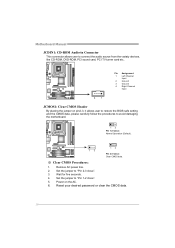
... Input 2 Ground 3 Ground 4 Right Channel Input 4 1 JCMOS1: Clear CMOS Header By placing the jumper on the AC. 6. Motherboard Manual JCDIN1: CD-ROM Audio-in Connector This connector allows user to avoid damaging the motherboard. 13 Pin 1-2 Close: Normal Operation (Default). 13 13 Pin 2-3 Close: Clear CMOS data. ※ Clear CMOS Procedures: 1. Set...
... Input 2 Ground 3 Ground 4 Right Channel Input 4 1 JCMOS1: Clear CMOS Header By placing the jumper on the AC. 6. Motherboard Manual JCDIN1: CD-ROM Audio-in Connector This connector allows user to avoid damaging the motherboard. 13 Pin 1-2 Close: Normal Operation (Default). 13 13 Pin 2-3 Close: Clear CMOS data. ※ Clear CMOS Procedures: 1. Set...

Setup Manual
Page 20
Pin Assignment 1 -Strobe 2 -ALF 3 Data 0 4 -Error 5 Data 1 6 -Init 7 Data 2 8 -Scltin 9 Data 3 10 Ground 11 Data 4 12 Ground 13 Data 5 25 1 2 Pin Assignment 14 Ground 15 Data 6 16 Ground 17 Data 7 18 Ground 19 -ACK 20 Ground 21 Busy 22 Ground 23 PE 24 Ground 25 SCLT 26 Key 18 Motherboard Manual JPRNT1: Printer Port Connector This header allows you to connector printer on the PC.
Pin Assignment 1 -Strobe 2 -ALF 3 Data 0 4 -Error 5 Data 1 6 -Init 7 Data 2 8 -Scltin 9 Data 3 10 Ground 11 Data 4 12 Ground 13 Data 5 25 1 2 Pin Assignment 14 Ground 15 Data 6 16 Ground 17 Data 7 18 Ground 19 -ACK 20 Ground 21 Busy 22 Ground 23 PE 24 Ground 25 SCLT 26 Key 18 Motherboard Manual JPRNT1: Printer Port Connector This header allows you to connector printer on the PC.
Setup Manual
Page 21
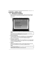
The setup guide will need Acrobat Reader to launch the installation program. C. Click on the Manual icon to browse for your motherboard and operating system. Click on each software title to launch the installation program. Note: You will list the compatible driver for ...for better system performance. B. A. Manual Aside from http://www.adobe.com /produ cts/a crobat /reads tep2 .html 19 CHAPTER 4: USEFUL HELP 945GC-M7 TE 4.1 DRIVER INSTALLATION NOTE After you installed your operating system, please insert the Fully Setup Driver CD into your optical drive and install the...
The setup guide will need Acrobat Reader to launch the installation program. C. Click on the Manual icon to browse for your motherboard and operating system. Click on each software title to launch the installation program. Note: You will list the compatible driver for ...for better system performance. B. A. Manual Aside from http://www.adobe.com /produ cts/a crobat /reads tep2 .html 19 CHAPTER 4: USEFUL HELP 945GC-M7 TE 4.1 DRIVER INSTALLATION NOTE After you installed your operating system, please insert the Fully Setup Driver CD into your optical drive and install the...
Setup Manual
Page 22
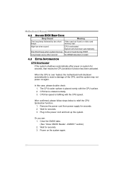
... data. (See "Close CMOS Header: JCMOS1" section) 2. Wait for seconds. 3. The CPU cooler surface is rotated normally. 3. Wait for seconds. 3. Motherboard Manual 4.2 AWARD BIOS BEEP CODE Beep Sound Meaning One long beep followed by two short Video card not found during POST Long beeps every other...is fulfilling with the CPU surface. 2. CPU fan is placed evenly with the CPU speed. CPU fan speed is over heated, the motherboard will shut down automatically One Short beep when system boot-up the system. After confirmed, please follow steps below to avoid a damage ...
... data. (See "Close CMOS Header: JCMOS1" section) 2. Wait for seconds. 3. The CPU cooler surface is rotated normally. 3. Wait for seconds. 3. Motherboard Manual 4.2 AWARD BIOS BEEP CODE Beep Sound Meaning One long beep followed by two short Video card not found during POST Long beeps every other...is fulfilling with the CPU surface. 2. CPU fan is placed evenly with the CPU speed. CPU fan speed is over heated, the motherboard will shut down automatically One Short beep when system boot-up the system. After confirmed, please follow steps below to avoid a damage ...
Setup Manual
Page 24
... when testing and results in the About panel, you do not need to a speed that is either the original system speed or a suitable one click. Motherboard Manual CHAPTER 5: WARPSPEEDER™ III 5.1 INTRODUCTION [WarpSpeeder™ III], a new powerful control utility, features three user-friendly functions including Overclock Manager, Overvoltage Manager, and Hardware...
... when testing and results in the About panel, you do not need to a speed that is either the original system speed or a suitable one click. Motherboard Manual CHAPTER 5: WARPSPEEDER™ III 5.1 INTRODUCTION [WarpSpeeder™ III], a new powerful control utility, features three user-friendly functions including Overclock Manager, Overvoltage Manager, and Hardware...

Setup Manual
Page 25
When you see the following dialog will change according to install. 2. 945GC-M7 TE 5.3 INSTALLATION 1. Click "Finish" button. Execute the setup execution file, and then the following dialog in this user manual will pop up. Please click "Next" button and follow the default procedure to your motherboard on hand. 23 Usage: The following figures are only for reference, the screen printed in setup procedure, it means setup is completed.
When you see the following dialog will change according to install. 2. 945GC-M7 TE 5.3 INSTALLATION 1. Click "Finish" button. Execute the setup execution file, and then the following dialog in this user manual will pop up. Please click "Next" button and follow the default procedure to your motherboard on hand. 23 Usage: The following figures are only for reference, the screen printed in setup procedure, it means setup is completed.
Setup Manual
Page 26
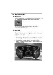
... like the icon shown below. The On/Off button is Main Panel. Contains About, Voltage/Overclock, and Hardware Monitor Buttons for closing the program. 24 Motherboard Manual 5.4 WARPSPEEDER™ III 1. Desktop Icon After the [WarpSpeeder™ III] has been installed, a [WarpSpeeder™ III] icon will be launched...
... like the icon shown below. The On/Off button is Main Panel. Contains About, Voltage/Overclock, and Hardware Monitor Buttons for closing the program. 24 Motherboard Manual 5.4 WARPSPEEDER™ III 1. Desktop Icon After the [WarpSpeeder™ III] has been installed, a [WarpSpeeder™ III] icon will be launched...
Setup Manual
Page 28
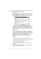
... button and [WarpSpeeder™ III] will restore to the hardware default setting. 26 "V3 Engine"/"V6 Engine"/"V9 Engine": Provide user the ability to proceed. Motherboard Manual Overclock Panel contains these features: a. After reboot, the [WarpSpeeder™ III] utility will proceed a testing for you that the system may become unstable, click...
... button and [WarpSpeeder™ III] will restore to the hardware default setting. 26 "V3 Engine"/"V6 Engine"/"V9 Engine": Provide user the ability to proceed. Motherboard Manual Overclock Panel contains these features: a. After reboot, the [WarpSpeeder™ III] utility will proceed a testing for you that the system may become unstable, click...

Setup Manual
Page 30
... following figure. About Panel Click the "about" button in hints of [WarpSpeeder™ III] utility. You can make [WarpSpeeder™ III] utility more robust. 28 Motherboard Manual 5.
... following figure. About Panel Click the "about" button in hints of [WarpSpeeder™ III] utility. You can make [WarpSpeeder™ III] utility more robust. 28 Motherboard Manual 5.

