Setup Manual
Page 3
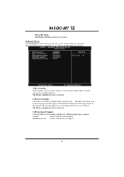
.... Before you start installing the motherboard, please make sure you follow the instructions below: „ Prepare a dry and stable working environment with sufficient lighting. „ Always disconnect the computer from power outlet before operation. „ Before you for ATX Case X 1 Installation Guide X 1 Fully Setup Driver CD X 1 (full version manual files inside the case after installation. CHAPTER 1: INTRODUCTION 945GC-M7 TE 1.1 BEFORE YOU START Thank you take the motherboard out from anti...
.... Before you start installing the motherboard, please make sure you follow the instructions below: „ Prepare a dry and stable working environment with sufficient lighting. „ Always disconnect the computer from power outlet before operation. „ Before you for ATX Case X 1 Installation Guide X 1 Fully Setup Driver CD X 1 (full version manual files inside the case after installation. CHAPTER 1: INTRODUCTION 945GC-M7 TE 1.1 BEFORE YOU START Thank you take the motherboard out from anti...
Setup Manual
Page 4
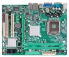
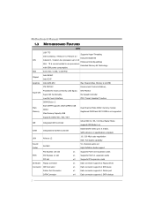
.../s. SATA Version 2.0 specification compliant. H/W Monitor Fan Speed Controller Low Pin Count Interface ITE's "Smart Guardian" function DIMM Slots x 2 Main Memory Each DIMM supports 256/512MB & 1GB DDR2 Max Memory Capacity 2GB Dual Channel Mode DDR2 memory module Registered DIMM and ECC DIMM is not supported Supports DDR2 400 / 533 / 667 IDE Integrated IDE Controller Ultra DMA 33 / 66 / 100 Bus Master Mode supports PIO Mode 0~4, SATA Integrated Serial ATA Controller Data transfer rates up to use processors Extended Memory 64 Technology with 95W power consumption. LAN Atheros...
.../s. SATA Version 2.0 specification compliant. H/W Monitor Fan Speed Controller Low Pin Count Interface ITE's "Smart Guardian" function DIMM Slots x 2 Main Memory Each DIMM supports 256/512MB & 1GB DDR2 Max Memory Capacity 2GB Dual Channel Mode DDR2 memory module Registered DIMM and ECC DIMM is not supported Supports DDR2 400 / 533 / 667 IDE Integrated IDE Controller Ultra DMA 33 / 66 / 100 Bus Master Mode supports PIO Mode 0~4, SATA Integrated Serial ATA Controller Data transfer rates up to use processors Extended Memory 64 Technology with 95W power consumption. LAN Atheros...
Setup Manual
Page 5
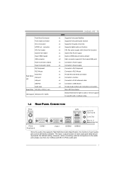
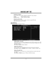
... audio jack listed above represents the default setting. However, when connecting external microphone to monitor. Front Panel Connector Front Audio Connector CD-in Connector S/PDIF out connector CPU Fan header System Fan header Clear CMOS header USB connector Power Connector (24pin) Power Connector (4pin) PS/2 Keyboard PS/2 Mouse Back Panel I/O Serial Port VGA port LAN port USB Port Audio Jack Board Size 190 (W) x 239 (L) mm OS Support Windows XP / VISTA 945GC-M7 TE SPEC x1 Supports front panel facilities x1 Supports front panel audio function x1 Supports CD audio...
... audio jack listed above represents the default setting. However, when connecting external microphone to monitor. Front Panel Connector Front Audio Connector CD-in Connector S/PDIF out connector CPU Fan header System Fan header Clear CMOS header USB connector Power Connector (24pin) Power Connector (4pin) PS/2 Keyboard PS/2 Mouse Back Panel I/O Serial Port VGA port LAN port USB Port Audio Jack Board Size 190 (W) x 239 (L) mm OS Support Windows XP / VISTA 945GC-M7 TE SPEC x1 Supports front panel facilities x1 Supports front panel audio function x1 Supports CD audio...

Setup Manual
Page 11
... installed CPU. Memory Capacity DIMM Socket Location DDR2_A1 DDR2_B1 DDR2 Module 256MB/512MB/1GB *1 256MB/512MB/1GB *1 945GC-M7 TE Total Memory Size Max memory 2GB. Please refer to the table below to the FSB frequency of the same density in pairs, shown in the following requirements: Install memory module of the installed CPU, the motherboard could support DDR2 400/533/667 modules. Dual Channel Status DDR2_A1 DDR2_B1 Disabled O X Disabled X O Enabled O O (O means memory installed...
... installed CPU. Memory Capacity DIMM Socket Location DDR2_A1 DDR2_B1 DDR2 Module 256MB/512MB/1GB *1 256MB/512MB/1GB *1 945GC-M7 TE Total Memory Size Max memory 2GB. Please refer to the table below to the FSB frequency of the same density in pairs, shown in the following requirements: Install memory module of the installed CPU, the motherboard could support DDR2 400/533/667 modules. Dual Channel Status DDR2_A1 DDR2_B1 Disabled O X Disabled X O Enabled O O (O means memory installed...

Setup Manual
Page 12
This connector supports the provided floppy drive ribbon cables. 33 1 34 2 IDE1: Hard Disk Connectors The motherboard has a 32-bit Enhanced PCI IDE Controller that supports 360K, 720K, 1.2M, 1.44M and 2.88M floppy disk types. Motherboard Manual 2.4 CONNECTORS AND SLOTS FDD1: Floppy Disk Connector The motherboard provides a standard floppy disk connector that provides PIO Mode 0~4, Bus Master, and Ultra DMA 33/66/100 functionality. The IDE connector can connect a master and a slave drive, so you can connect up to two hard disk drives. 40 39 2 1 10
This connector supports the provided floppy drive ribbon cables. 33 1 34 2 IDE1: Hard Disk Connectors The motherboard has a 32-bit Enhanced PCI IDE Controller that supports 360K, 720K, 1.2M, 1.44M and 2.88M floppy disk types. Motherboard Manual 2.4 CONNECTORS AND SLOTS FDD1: Floppy Disk Connector The motherboard provides a standard floppy disk connector that provides PIO Mode 0~4, Bus Master, and Ultra DMA 33/66/100 functionality. The IDE connector can connect a master and a slave drive, so you can connect up to two hard disk drives. 40 39 2 1 10
Setup Manual
Page 14
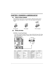
... 5 HDD LED (+) 6 HDD LED (-) 7 Ground 8 Reset control Function Pin 9 Speaker 10 Connector 11 12 Hard drive 13 LED 14 Reset button 15 16 Assignment Sleep control Ground N/A Power LED (+) Power LED (+) Power LED (-) Power button Ground Function Sleep button N/A Power LED Power-on , Reset, HDD LED, Power LED, Sleep button, and speaker connections. Pin opened Pin closed 3.2 DETAIL SETTINGS Pin1-2 closed JPANEL1: Front Panel Header This 16-pin connector includes Power-on button 12 Motherboard Manual CHAPTER 3: HEADERS & JUMPERS SETUP 3.1 HOW TO SETUP JUMPERS The...
... 5 HDD LED (+) 6 HDD LED (-) 7 Ground 8 Reset control Function Pin 9 Speaker 10 Connector 11 12 Hard drive 13 LED 14 Reset button 15 16 Assignment Sleep control Ground N/A Power LED (+) Power LED (+) Power LED (-) Power button Ground Function Sleep button N/A Power LED Power-on , Reset, HDD LED, Power LED, Sleep button, and speaker connections. Pin opened Pin closed 3.2 DETAIL SETTINGS Pin1-2 closed JPANEL1: Front Panel Header This 16-pin connector includes Power-on button 12 Motherboard Manual CHAPTER 3: HEADERS & JUMPERS SETUP 3.1 HOW TO SETUP JUMPERS The...
Setup Manual
Page 22
... CMOS Header: JCMOS1" section) 2. Power on system for seconds. 3. In this case, please double check: 1. CPU fan speed is placed evenly with the CPU speed. Plug in the power cord and boot up No error found or video card beeps memory bad High-low siren sound CPU overheated System will shutdown automatically to relief the CPU 0protection function. 1. Motherboard Manual 4.2 AWARD BIOS BEEP CODE Beep Sound Meaning One long beep followed by two short Video card not found during POST Long beeps every other second No DRAM detected...
... CMOS Header: JCMOS1" section) 2. Power on system for seconds. 3. In this case, please double check: 1. CPU fan speed is placed evenly with the CPU speed. Plug in the power cord and boot up No error found or video card beeps memory bad High-low siren sound CPU overheated System will shutdown automatically to relief the CPU 0protection function. 1. Motherboard Manual 4.2 AWARD BIOS BEEP CODE Beep Sound Meaning One long beep followed by two short Video card not found during POST Long beeps every other second No DRAM detected...
Setup Manual
Page 24
... Hardware Monitor smartly indicates the temperatures, voltage and CPU fan speed as well as the chipset information. In addition, the frequency status of CPU, memory, VGA and PCI along with just one . 5.2 SYSTEM REQUIREMENT OS Support: Windows 98 SE, Windows Me, Windows XP, Windows Vista DirectX: DirectX 8.1 or above. (The Windows XP operating system includes DirectX 8.1. Moreover, to power up CPU core voltage and Memory voltage. Motherboard Manual CHAPTER 5: WARPSPEEDER™ III 5.1 INTRODUCTION [WarpSpeeder™ III], a new powerful control utility...
... Hardware Monitor smartly indicates the temperatures, voltage and CPU fan speed as well as the chipset information. In addition, the frequency status of CPU, memory, VGA and PCI along with just one . 5.2 SYSTEM REQUIREMENT OS Support: Windows 98 SE, Windows Me, Windows XP, Windows Vista DirectX: DirectX 8.1 or above. (The Windows XP operating system includes DirectX 8.1. Moreover, to power up CPU core voltage and Memory voltage. Motherboard Manual CHAPTER 5: WARPSPEEDER™ III 5.1 INTRODUCTION [WarpSpeeder™ III], a new powerful control utility...
Bios Setup
Page 2
... the ACPI specification, developed by this manual is a custom version of an industry standard BIOS. The rest of the chipset controlling the entire system. EPA Green PC Support This PHOENIX-AWARD BIOS supports Version 1.03 of the Advanced Power Management (APM) specification. It provides ASL code for power management and device configuration capabilities as disk drives and serial and parallel ports. The Phoenix-Award BIOS™ installed in battery-backed RAM so that it retains the Setup information...
... the ACPI specification, developed by this manual is a custom version of an industry standard BIOS. The rest of the chipset controlling the entire system. EPA Green PC Support This PHOENIX-AWARD BIOS supports Version 1.03 of the Advanced Power Management (APM) specification. It provides ASL code for power management and device configuration capabilities as disk drives and serial and parallel ports. The Phoenix-Award BIOS™ installed in battery-backed RAM so that it retains the Setup information...
Bios Setup
Page 11
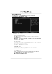
...: Disabled, Enabled (default). 10 945GC-M7 TE Hard Disk Boot Priority These BIOS attempt to load from the device in the sequence selected in Cards. This will test the floppy drives to swap logical drive assignments. Master, Pri.Slave, Sec.Master, Sec.Slave, USBHDD0, USBHDD1, USBHDD2 and Bootable Add-in these items. The Choices: Floppy, LS120, Hard Disk, CDROM, ZIP100, USB-FDD, USB-ZIP, USB-CDROM, LAN, Disabled. The Choices: Enabled (default), Disabled Swap Floppy Drive For...
...: Disabled, Enabled (default). 10 945GC-M7 TE Hard Disk Boot Priority These BIOS attempt to load from the device in the sequence selected in Cards. This will test the floppy drives to swap logical drive assignments. Master, Pri.Slave, Sec.Master, Sec.Slave, USBHDD0, USBHDD1, USBHDD2 and Bootable Add-in these items. The Choices: Floppy, LS120, Hard Disk, CDROM, ZIP100, USB-FDD, USB-ZIP, USB-CDROM, LAN, Disabled. The Choices: Enabled (default), Disabled Swap Floppy Drive For...

Bios Setup
Page 12
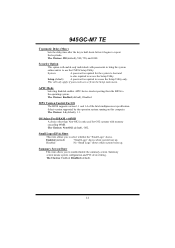
... IDE Hard Disk boot sector. "Enabled" for Windows XP and Linux 2.4.x (OS optimized for Hyper-Threading Technology.) "Disabled" for other OS (OS not optimized for Win95 The Choices: NO (default), YES. The Choices: Disabled (default), Enabled. Virus Warning This option allows you power up the computer. Typematic Rate (Chars/Sec) Sets the rate at a rate determined by the keyboard controller. Disabled (default) Virus protection is arrow keys. Enabled (default) Enable quick POST. Typematic Rate Setting...
... IDE Hard Disk boot sector. "Enabled" for Windows XP and Linux 2.4.x (OS optimized for Hyper-Threading Technology.) "Disabled" for other OS (OS not optimized for Win95 The Choices: NO (default), YES. The Choices: Disabled (default), Enabled. Virus Warning This option allows you power up the computer. Typematic Rate (Chars/Sec) Sets the rate at a rate determined by the keyboard controller. Disabled (default) Virus protection is arrow keys. Enabled (default) Enable quick POST. Typematic Rate Setting...
Bios Setup
Page 13
... online and/or to use the CMOS Setup Utility. The Choices: 1.4 (default), 1.1. Setup (default) A password is also required to the operating system. Security Option This option will only apply if passwords are set from the BIOS to access the Setup Utility. Enabled (default) "Small Logo" shows when system boot up . Summary screen means system configuration and PCI device listing. Select version supported by the operation system running on this computer. APIC Mode Selecting Enabled enables APIC device mode reporting from the Setup main menu.
... online and/or to use the CMOS Setup Utility. The Choices: 1.4 (default), 1.1. Setup (default) A password is also required to the operating system. Security Option This option will only apply if passwords are set from the BIOS to access the Setup Utility. Enabled (default) "Small Logo" shows when system boot up . Summary screen means system configuration and PCI device listing. Select version supported by the operation system running on this computer. APIC Mode Selecting Enabled enables APIC device mode reporting from the Setup main menu.
Bios Setup
Page 14
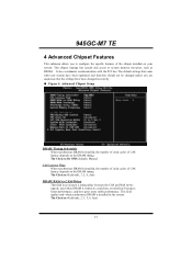
... changed unless you are suspicious that came with the PCI bus. The Choices: 4 (default), 2, 3, 5, 6, Auto. 13 and slow gives more stable performance. It also coordinates communications with your system. DRAM RAS# to CAS# Delay This field let you insert a timing delay between the CAS and RAS strobe signals, used when DRAM is installed in the system. 945GC-M7 TE 4 Advanced Chipset...
... changed unless you are suspicious that came with the PCI bus. The Choices: 4 (default), 2, 3, 5, 6, Auto. 13 and slow gives more stable performance. It also coordinates communications with your system. DRAM RAS# to CAS# Delay This field let you insert a timing delay between the CAS and RAS strobe signals, used when DRAM is installed in the system. 945GC-M7 TE 4 Advanced Chipset...
Bios Setup
Page 15
... (tRAS) This item controls the number of DRAM clocks to guarantee the DRAM has been safely power-cycled. However, if any program writes to this memory area, a system error may result. 945GC-M7 TE DRAM RAS# Precharge If an insufficient number of cycles is installed in the system. Fast gives faster performance; The Choices: 4 (default), 2, 3, 5, 6, Auto. The Choices: Auto (default), Onchip VGA, PEG Port. The Choices: 4 to...
... (tRAS) This item controls the number of DRAM clocks to guarantee the DRAM has been safely power-cycled. However, if any program writes to this memory area, a system error may result. 945GC-M7 TE DRAM RAS# Precharge If an insufficient number of cycles is installed in the system. Fast gives faster performance; The Choices: 4 (default), 2, 3, 5, 6, Auto. The Choices: Auto (default), Onchip VGA, PEG Port. The Choices: 4 to...

Bios Setup
Page 18
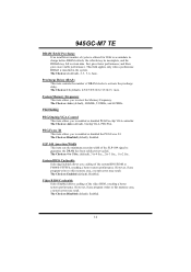
... SATA only. Modes 0 to enable BIOS support. The Choices: Enabled (default), Disabled. On-Chip Serial ATA This item allows you to enable or disable the IDE transfer access. SATA PORT Speed Settings The Choices: Disabled (default), Force GEN I, Force GEN II. 17 IDE DMA Transfer Access This item allows you to enable or disable the primary/ secondary IDE Channel. The Choices: Enabled (default), Disabled. The Choices: Auto (default), Disabled. If your system software both SATA and PATA max of the IDE devices that the onboard IDE interface supports. If your hard drive...
... SATA only. Modes 0 to enable BIOS support. The Choices: Enabled (default), Disabled. On-Chip Serial ATA This item allows you to enable or disable the IDE transfer access. SATA PORT Speed Settings The Choices: Disabled (default), Force GEN I, Force GEN II. 17 IDE DMA Transfer Access This item allows you to enable or disable the primary/ secondary IDE Channel. The Choices: Enabled (default), Disabled. The Choices: Auto (default), Disabled. If your system software both SATA and PATA max of the IDE devices that the onboard IDE interface supports. If your hard drive...
Bios Setup
Page 19
945GC-M7 TE PATA IDE Mode The Choices: Primary (default), Secondary. The Choices: Enabled (default), Disabled USB 2.0 Controller This entry is to enable or disable the USB Keyboard Legacy Support. Enabled Enable USB Keyboard Support. Onboard Device If you highlight the literal "Press Enter" next to the "Onboard Device" label and then press the enter key, it will automatically turn on, when high speed device were attached. This BIOS itself may/ may not have USB peripherals. USB Keyboard Support This item allows you have high speed USB support. Disabled (default) Disable...
945GC-M7 TE PATA IDE Mode The Choices: Primary (default), Secondary. The Choices: Enabled (default), Disabled USB 2.0 Controller This entry is to enable or disable the USB Keyboard Legacy Support. Enabled Enable USB Keyboard Support. Onboard Device If you highlight the literal "Press Enter" next to the "Onboard Device" label and then press the enter key, it will automatically turn on, when high speed device were attached. This BIOS itself may/ may not have USB peripherals. USB Keyboard Support This item allows you have high speed USB support. Disabled (default) Disable...
Bios Setup
Page 20
... use it. Super IO Device Press Enter to configure the Super I /O Address. Onboard FDC Controller Select Enabled if your system has a floppy disk controller (FDC) installed on the system board and you to decide to enable or disable to support HD Audio. Disabled (default) Disable USB Mouse Support. The Choices: 378/IRQ7 (default), 278/IRQ5, 3BC/IRQ7, Disabled. 19 Enabled Enable USB Mouse Support. The Choices: Enabled (default), Disabled. Onboard Parallel Port This item allows you to enable or disable the USB Mouse Legacy Support. 945GC-M7 TE USB...
... use it. Super IO Device Press Enter to configure the Super I /O Address. Onboard FDC Controller Select Enabled if your system has a floppy disk controller (FDC) installed on the system board and you to decide to enable or disable to support HD Audio. Disabled (default) Disable USB Mouse Support. The Choices: 378/IRQ7 (default), 278/IRQ5, 3BC/IRQ7, Disabled. 19 Enabled Enable USB Mouse Support. The Choices: Enabled (default), Disabled. Onboard Parallel Port This item allows you to enable or disable the USB Mouse Legacy Support. 945GC-M7 TE USB...

Bios Setup
Page 23
... the system will boot up from S3 state. 945GC-M7 TE ACPI Function This item displays the status of the VGA card does not support the initialization feature, the display may work . 22 The Choices: Auto (default), Yes, No. Note: If you have changed the setting, you disable the function, but system will make BIOS run VGA BIOS to initialize the card. The Choices: Enabled (default), Disabled. ACPI Suspend Type The item allows...
... the system will boot up from S3 state. 945GC-M7 TE ACPI Function This item displays the status of the VGA card does not support the initialization feature, the display may work . 22 The Choices: Auto (default), Yes, No. Note: If you have changed the setting, you disable the function, but system will make BIOS run VGA BIOS to initialize the card. The Choices: Enabled (default), Disabled. ACPI Suspend Type The item allows...
Bios Setup
Page 26
...: 32-bit mode (default), 64-bit mode. 25 The Choices: Delay 4 Sec, Instant-Off (default). 945GC-M7 TE Suspend Mode The item allows you to the video buffer. Blank Screen This option only writes blanks to select the suspend type under ACPI operating system. HDD Power Down When enabled, the hard disk drive will cause the system to turn off the vertical and horizontal synchronization ports and write blanks to enter the...
...: 32-bit mode (default), 64-bit mode. 25 The Choices: Delay 4 Sec, Instant-Off (default). 945GC-M7 TE Suspend Mode The item allows you to the video buffer. Blank Screen This option only writes blanks to select the suspend type under ACPI operating system. HDD Power Down When enabled, the hard disk drive will cause the system to turn off the vertical and horizontal synchronization ports and write blanks to enter the...
Bios Setup
Page 28
...-VGA graphic controller watch for Transaction packets (TLP). Enabled Enable the function. 945GC-M7 TE IRQ Resources This submenu will allow you to configure the system interrupts. Some graphic controllers that will not show up on the ISA bus. Disabled (default) Disable the function. Maximum Payload Size Set the maximum payload size for the Write access to provide boot information and VGA compatibility. In this option. When you press the "Press Enter...
...-VGA graphic controller watch for Transaction packets (TLP). Enabled Enable the function. 945GC-M7 TE IRQ Resources This submenu will allow you to configure the system interrupts. Some graphic controllers that will not show up on the ISA bus. Disabled (default) Disable the function. Maximum Payload Size Set the maximum payload size for the Write access to provide boot information and VGA compatibility. In this option. When you press the "Press Enter...


