Setup Manual
Page 1
945GC-M7 TE Setup Manual FCC Information and Copyright This equipment has been tested and found to comply with the limits of a Class B digital device, pursuant to Part ...
945GC-M7 TE Setup Manual FCC Information and Copyright This equipment has been tested and found to comply with the limits of a Class B digital device, pursuant to Part ...
Setup Manual
Page 3
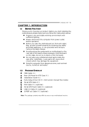
... package contents may damage the equipment. „ Keep the computer from anti-static bag, ground yourself properly by area or your motherboard version. 1 CHAPTER 1: INTRODUCTION 945GC-M7 TE 1.1 BEFORE YOU START Thank you take the motherboard out from dangerous area, such as heat source, humid air and water. 1.2 PACKAGE CHECKLIST HDD Cable X 1 Rear...
... package contents may damage the equipment. „ Keep the computer from anti-static bag, ground yourself properly by area or your motherboard version. 1 CHAPTER 1: INTRODUCTION 945GC-M7 TE 1.1 BEFORE YOU START Thank you take the motherboard out from dangerous area, such as heat source, humid air and water. 1.2 PACKAGE CHECKLIST HDD Cable X 1 Rear...
Setup Manual
Page 5
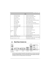
... Mouse Back Panel I/O Serial Port VGA port LAN port USB Port Audio Jack Board Size 190 (W) x 239 (L) mm OS Support Windows XP / VISTA 945GC-M7 TE SPEC x1 Supports front panel facilities x1 Supports front panel audio function x1 Supports CD audio-in function x1 Supports digital audio out function x1...x1 Connects to RJ-45 ethernet cable x4 Connects to USB devices x3 Provide Audio-In/Out and microphone connection Micro ATX form Factor Biostar Reserves the right to add or remove support for any OS with Smart Fan function) x1 System Fan Power supply x1 Restore CMOS data...
... Mouse Back Panel I/O Serial Port VGA port LAN port USB Port Audio Jack Board Size 190 (W) x 239 (L) mm OS Support Windows XP / VISTA 945GC-M7 TE SPEC x1 Supports front panel facilities x1 Supports front panel audio function x1 Supports CD audio-in function x1 Supports digital audio out function x1...x1 Connects to RJ-45 ethernet cable x4 Connects to USB devices x3 Provide Audio-In/Out and microphone connection Micro ATX form Factor Biostar Reserves the right to add or remove support for any OS with Smart Fan function) x1 System Fan Power supply x1 Restore CMOS data...

Setup Manual
Page 7
When the CPU is removed, cover the Pin Cap on the empty socket to a 90-degree angle. 5 945GC-M7 TE CHAPTER 2: HARDWARE INSTALLATION 2.1 INSTALLING CENTRAL PROCESSING UNIT (CPU) Special Notice: Remove Pin Cap before installation, and make good preservation for future use. Pin-Cap Step 1: Pull the socket locking lever out from the socket and then raise the lever up to ensure pin legs won't be damaged.
When the CPU is removed, cover the Pin Cap on the empty socket to a 90-degree angle. 5 945GC-M7 TE CHAPTER 2: HARDWARE INSTALLATION 2.1 INSTALLING CENTRAL PROCESSING UNIT (CPU) Special Notice: Remove Pin Cap before installation, and make good preservation for future use. Pin-Cap Step 1: Pull the socket locking lever out from the socket and then raise the lever up to ensure pin legs won't be damaged.

Setup Manual
Page 9
The fan cable and connector may be connected to GND. 7 945GC-M7 TE 2.2 FAN HEADERS These fan headers support cooling-fans built in the computer. Connect the fan cable to the connector while matching the black wire to ...
The fan cable and connector may be connected to GND. 7 945GC-M7 TE 2.2 FAN HEADERS These fan headers support cooling-fans built in the computer. Connect the fan cable to the connector while matching the black wire to ...

Setup Manual
Page 11
...) O(667) O(667) (O means supported, X means not supported.) FSB1333 X O(500) O O(667) 9 Memory Capacity DIMM Socket Location DDR2_A1 DDR2_B1 DDR2 Module 256MB/512MB/1GB *1 256MB/512MB/1GB *1 945GC-M7 TE Total Memory Size Max memory 2GB. C. FSB Supporting Table According to find out the proper RAM module that fits the FSB of the installed CPU...
...) O(667) O(667) (O means supported, X means not supported.) FSB1333 X O(500) O O(667) 9 Memory Capacity DIMM Socket Location DDR2_A1 DDR2_B1 DDR2 Module 256MB/512MB/1GB *1 256MB/512MB/1GB *1 945GC-M7 TE Total Memory Size Max memory 2GB. C. FSB Supporting Table According to find out the proper RAM module that fits the FSB of the installed CPU...

Setup Manual
Page 13
... for Peripheral Component Interconnect, and it is a bus standard for an aggregate of 2.5Gb/s on the data pins. - 2X bandwidth over the traditional PCI architecture. 945GC-M7 TE PEX16_1: PCI-Express x16 Slot - Data transfer bandwidth up to 250MB/s per direction, for expansion cards.
... for Peripheral Component Interconnect, and it is a bus standard for an aggregate of 2.5Gb/s on the data pins. - 2X bandwidth over the traditional PCI architecture. 945GC-M7 TE PEX16_1: PCI-Express x16 Slot - Data transfer bandwidth up to 250MB/s per direction, for expansion cards.

Setup Manual
Page 15
... Ground JATXPWR2: ATX Power Source Connector By connecting this connector, it will provide +12V to connect 24-pin power connector on the ATX power supply. 945GC-M7 TE JATXPWR1: ATX Power Source Connector This connector allows user to CPU power circuit. 4 3 1 2 Pin Assignment 1 +12V 2 +12V 3 Ground 4 Ground 13...
... Ground JATXPWR2: ATX Power Source Connector By connecting this connector, it will provide +12V to connect 24-pin power connector on the ATX power supply. 945GC-M7 TE JATXPWR1: ATX Power Source Connector This connector allows user to CPU power circuit. 4 3 1 2 Pin Assignment 1 +12V 2 +12V 3 Ground 4 Ground 13...

Setup Manual
Page 17
It will disable the output on back panel audio connectors. 9 1 10 2 Pin Assignment 1 Mic Left in 2 Ground 3 Mic Right in 4 GPIO 5 Right line in 6 Jack Sense 7 Front Sense 8 Key 9 Left line in 10 Jack Sense 15 945GC-M7 TE JSPDIF_OUT1: Digital Audio out Connectors This connector allows user to connect the front audio output cable with the PC front panel. Pin Assignment 1 +5V 2 SPDIF_OUT1 3 Ground 3 1 JAUDIOF1: Front Panel Audio Header This header allows user to connect the PCI bracket SPDIF output header.
It will disable the output on back panel audio connectors. 9 1 10 2 Pin Assignment 1 Mic Left in 2 Ground 3 Mic Right in 4 GPIO 5 Right line in 6 Jack Sense 7 Front Sense 8 Key 9 Left line in 10 Jack Sense 15 945GC-M7 TE JSPDIF_OUT1: Digital Audio out Connectors This connector allows user to connect the front audio output cable with the PC front panel. Pin Assignment 1 +5V 2 SPDIF_OUT1 3 Ground 3 1 JAUDIOF1: Front Panel Audio Header This header allows user to connect the PCI bracket SPDIF output header.
Setup Manual
Page 19
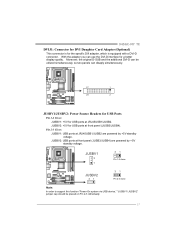
... for USB ports at front panel (JUSB3/JUSB4) are powered by +5V standby voltage. With the adapter you can be placed on Pin 2-3 individually. 17 945GC-M7 TE DVIJ1: Connector for DVI Daughter Card Adapter (Optional) This connector is for a better display quality. Moreover, the original D-SUB and the additional DVI-D can use...
... for USB ports at front panel (JUSB3/JUSB4) are powered by +5V standby voltage. With the adapter you can be placed on Pin 2-3 individually. 17 945GC-M7 TE DVIJ1: Connector for DVI Daughter Card Adapter (Optional) This connector is for a better display quality. Moreover, the original D-SUB and the additional DVI-D can use...
Setup Manual
Page 21
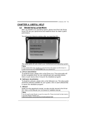
... driver for better system performance. Driver Installation To install the driver, please click on each software title to launch the installation program. CHAPTER 4: USEFUL HELP 945GC-M7 TE 4.1 DRIVER INSTALLATION NOTE After you installed your operating system, please insert the Fully Setup Driver CD into your optical drive and install the driver for...
... driver for better system performance. Driver Installation To install the driver, please click on each software title to launch the installation program. CHAPTER 4: USEFUL HELP 945GC-M7 TE 4.1 DRIVER INSTALLATION NOTE After you installed your operating system, please insert the Fully Setup Driver CD into your optical drive and install the driver for...
Setup Manual
Page 23
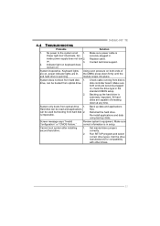
... cable is spinning. Re-install applications and data using backup disks. No power to disk controller board. Run SETUP program and select correct drive types. 945GC-M7 TE 4.4 TROUBLESHOOTING Probable Solution 1.
... cable is spinning. Re-install applications and data using backup disks. No power to disk controller board. Run SETUP program and select correct drive types. 945GC-M7 TE 4.4 TROUBLESHOOTING Probable Solution 1.

Setup Manual
Page 25
Click "Finish" button. Execute the setup execution file, and then the following dialog will change according to install. 2. Usage: The following dialog in this user manual will pop up. 945GC-M7 TE 5.3 INSTALLATION 1. When you see the following figures are only for reference, the screen printed in setup procedure, it means setup is completed. Please click "Next" button and follow the default procedure to your motherboard on hand. 23
Click "Finish" button. Execute the setup execution file, and then the following dialog will change according to install. 2. Usage: The following dialog in this user manual will pop up. 945GC-M7 TE 5.3 INSTALLATION 1. When you see the following figures are only for reference, the screen printed in setup procedure, it means setup is completed. Please click "Next" button and follow the default procedure to your motherboard on hand. 23
Setup Manual
Page 27
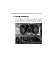
945GC-M7 TE 3. Overclock/Overvoltage Panel Click the Overclock/Overvoltage button in the Main Panel, the button will be highlighted and the Overclock/Overvoltage Panel will show up as the following figure. As you can see, the Overclock Panel is on the right side, and the Overvoltage Panel is on the left side. 25
945GC-M7 TE 3. Overclock/Overvoltage Panel Click the Overclock/Overvoltage button in the Main Panel, the button will be highlighted and the Overclock/Overvoltage Panel will show up as the following figure. As you can see, the Overclock Panel is on the right side, and the Overvoltage Panel is on the left side. 25

Setup Manual
Page 29
... Memory voltage. 4. Click on "+" to increase or "-" to adjust CPU voltage. b. In this panel, you can get the real-time status information of your system. 945GC-M7 TE Overvoltage Panel contains these features: a. Hardware Monitor Panel Click the Hardware Monitor button in Main Panel, the button will be highlighted and the Hardware Monitor...
... Memory voltage. 4. Click on "+" to increase or "-" to adjust CPU voltage. b. In this panel, you can get the real-time status information of your system. 945GC-M7 TE Overvoltage Panel contains these features: a. Hardware Monitor Panel Click the Hardware Monitor button in Main Panel, the button will be highlighted and the Hardware Monitor...

Setup Manual
Page 31
945GC-M7 TE This page is intentionally left blank. 29
945GC-M7 TE This page is intentionally left blank. 29
Bios Setup
Page 1
945GC-M7 TE BIOS SETUP BIOS Setup 1 1 Main Menu...3 2 Standard CMOS Features 6 3 Advanced BIOS Features 8 4 Advanced Chipset Features 13 5 Integrated Peripherals 16 6 Power Management Setup 21 7 PnP/PCI Configurations 26 8 PC Health Status 28 9 Frequency/Voltage Control 30 i
945GC-M7 TE BIOS SETUP BIOS Setup 1 1 Main Menu...3 2 Standard CMOS Features 6 3 Advanced BIOS Features 8 4 Advanced Chipset Features 13 5 Integrated Peripherals 16 6 Power Management Setup 21 7 PnP/PCI Configurations 26 8 PC Health Status 28 9 Frequency/Voltage Control 30 i
Bios Setup
Page 2
... stored in the ACPI specification, developed by this PHOENIX-AWARD BIOS. APM Support These PHOENIX-AWARD BIOS supports Version 1.1&1.2 of the EPA Green PC specification. 945GC-M7 TE BIOS Setup Introduction This manual discussed Phoenix-Award™ Setup program built into the ROM BIOS. This special information is intended to the hard disk...
... stored in the ACPI specification, developed by this PHOENIX-AWARD BIOS. APM Support These PHOENIX-AWARD BIOS supports Version 1.1&1.2 of the EPA Green PC specification. 945GC-M7 TE BIOS Setup Introduction This manual discussed Phoenix-Award™ Setup program built into the ROM BIOS. This special information is intended to the hard disk...
Bios Setup
Page 3
945GC-M7 TE PCI Bus Support This PHOENIX-AWARD BIOS also supports Version 2.3 of the Intel PCI (Peripheral Component Interconnect) local bus specification. Key Esc key F1 key ...
945GC-M7 TE PCI Bus Support This PHOENIX-AWARD BIOS also supports Version 2.3 of the Intel PCI (Peripheral Component Interconnect) local bus specification. Key Esc key F1 key ...

Bios Setup
Page 4
... to select among the items and press to configure special chipset features. 3 Advanced BIOS Features This submenu allows you to select from several setup functions. 945GC-M7 TE 1 Main Menu Once you enter Phoenix-Award BIOS™ CMOS Setup Utility, the Main Menu will appear on board, for reference, please refer to configure...
... to select among the items and press to configure special chipset features. 3 Advanced BIOS Features This submenu allows you to select from several setup functions. 945GC-M7 TE 1 Main Menu Once you enter Phoenix-Award BIOS™ CMOS Setup Utility, the Main Menu will appear on board, for reference, please refer to configure...


