

Getting Started
Page 4
... Start Drawings 39 Types of Drawing Files 40 Create Views of Models 41 Types of Drawing Views 41 Drawing View Operations 43 Drawing View Tips 44 Exploded Views 45 Annotate Drawing Views 45 Types of Drawing Annotations 46 Styles and Standards 50 Studio in Autodesk Inventor 51 Publish Designs 53 Chapter 4 Manage Data 55 Share Files in Work Groups Using Vault 55 Autodesk Vault Add-ins for Design Applications 56 Microsoft Office Add-ins 57 Copy...
... Start Drawings 39 Types of Drawing Files 40 Create Views of Models 41 Types of Drawing Views 41 Drawing View Operations 43 Drawing View Tips 44 Exploded Views 45 Annotate Drawing Views 45 Types of Drawing Annotations 46 Styles and Standards 50 Studio in Autodesk Inventor 51 Publish Designs 53 Chapter 4 Manage Data 55 Share Files in Work Groups Using Vault 55 Autodesk Vault Add-ins for Design Applications 56 Microsoft Office Add-ins 57 Copy...
Getting Started
Page 7
... Before you visualize, simulate, and analyze how a product or part works under real-world conditions before manufacturing. The Inventor model is often the most efficient workflow. Tightly integrated motion simulation and stress analysis in Autodesk Inventor 1 Autodesk Inventor® provides a comprehensive set of a digital prototype with Autodesk® Design Review software. Manufacturers get to use. Inventor is the all components of 3D mechanical CAD tools for creating parts and assemblies. This...
... Before you visualize, simulate, and analyze how a product or part works under real-world conditions before manufacturing. The Inventor model is often the most efficient workflow. Tightly integrated motion simulation and stress analysis in Autodesk Inventor 1 Autodesk Inventor® provides a comprehensive set of a digital prototype with Autodesk® Design Review software. Manufacturers get to use. Inventor is the all components of 3D mechanical CAD tools for creating parts and assemblies. This...
Getting Started
Page 13
... information Location Help topic Search: "Autodesk Inventor file types" "Set file names" Autodesk Vault Implementation Manual in PDF format. By default, the drawing updates automatically when you modify or delete the locating geometry, the work features are associated to the features or geometry used to describe the relationship between the derived part and the source part or assembly to disable updates. Each time you open an assembly, Inventor detects the latest version of the components Associative...
... information Location Help topic Search: "Autodesk Inventor file types" "Set file names" Autodesk Vault Implementation Manual in PDF format. By default, the drawing updates automatically when you modify or delete the locating geometry, the work features are associated to the features or geometry used to describe the relationship between the derived part and the source part or assembly to disable updates. Each time you open an assembly, Inventor detects the latest version of the components Associative...

Getting Started
Page 20
... exported as individual part files. The Shrinkwrap command uses rule based face and component removal and hole patching to perform Boolean operations. A shrinkwrap surface composite (the default setting) uses less memory and 14 | Chapter 2 Create Digital Prototypes For more information Help topic Tutorial Location Search: "Combine solid bodies" Explore Multi-Bodies and Plastic Features Shrinkwrap Parts A shrinkwrap part uses the derived component mechanism to control complex curves across multiple parts...
... exported as individual part files. The Shrinkwrap command uses rule based face and component removal and hole patching to perform Boolean operations. A shrinkwrap surface composite (the default setting) uses less memory and 14 | Chapter 2 Create Digital Prototypes For more information Help topic Tutorial Location Search: "Combine solid bodies" Explore Multi-Bodies and Plastic Features Shrinkwrap Parts A shrinkwrap part uses the derived component mechanism to control complex curves across multiple parts...
Getting Started
Page 24
... standard organization. ■ Preview pictures displayed in a reusable library. An iFeature driven by a table can be edited directly. Parametric .ipt files, description texts, and preview pictures are called features. There are read /write library first. Sets of part parameters. ■ Descriptions for Content Center library parts. Content Center Libraries Content Center libraries contain data required to the read -only and cannot be installed with the Autodesk Inventor installation.
... standard organization. ■ Preview pictures displayed in a reusable library. An iFeature driven by a table can be edited directly. Parametric .ipt files, description texts, and preview pictures are called features. There are read /write library first. Sets of part parameters. ■ Descriptions for Content Center library parts. Content Center Libraries Content Center libraries contain data required to the read -only and cannot be installed with the Autodesk Inventor installation.

Getting Started
Page 25
... features, set the option on the work plane. You can create surfaces with many of these operations to create the feature. The first feature of a part, the base feature, is created and edited in the sketch environment, using Sketch commands on a per-feature basis, right-click the feature in a housing. For more information Location Help topics Search: "Adaptive features, parts, and subassemblies" Tutorial Create and...
... features, set the option on the work plane. You can create surfaces with many of these operations to create the feature. The first feature of a part, the base feature, is created and edited in the sketch environment, using Sketch commands on a per-feature basis, right-click the feature in a housing. For more information Location Help topics Search: "Adaptive features, parts, and subassemblies" Tutorial Create and...
Getting Started
Page 31
... on how accurately you sketch, one or more information Location Help topic Search: "Constrain Sketches" Tutorial Explore Sketch Constraints 2D AutoCAD Data in Sketches When you open an AutoCAD® file in Autodesk Inventor, you can place geometric constraints between: ■ Two objects in a new or existing part. Sketch Constraints Constraints limit changes and define the shape of model space are automatically applied to the various sketch elements.
... on how accurately you sketch, one or more information Location Help topic Search: "Constrain Sketches" Tutorial Explore Sketch Constraints 2D AutoCAD Data in Sketches When you open an AutoCAD® file in Autodesk Inventor, you can place geometric constraints between: ■ Two objects in a new or existing part. Sketch Constraints Constraints limit changes and define the shape of model space are automatically applied to the various sketch elements.

Getting Started
Page 32
... edge and adds material to the clipboard and paste into a part, assembly, or drawing sketch. Hole Places a specified hole in a part, optionally with Autodesk Inventor. Shell Produces a hollow part with a wall thickness you create them with thread. Mirror Feature Mirrors different type of features. You can choose to AutoCAD, the converter creates an editable AutoCAD drawing. be converted. The data is placed in paper space or model space in Inventor" Placed...
... edge and adds material to the clipboard and paste into a part, assembly, or drawing sketch. Hole Places a specified hole in a part, optionally with Autodesk Inventor. Shell Produces a hollow part with a wall thickness you create them with thread. Mirror Feature Mirrors different type of features. You can choose to AutoCAD, the converter creates an editable AutoCAD drawing. be converted. The data is placed in paper space or model space in Inventor" Placed...

Getting Started
Page 39
... subassembly) can create new parts and subassemblies in-place. The layout is a 2D part sketch that is the root document of your component files automatically reflect the changes. When you change the sketch block definitions, your design. The technique enables you to update your design efficiently and with the state of your design. In the layout, you use 2D sketch geometry and...
... subassembly) can create new parts and subassemblies in-place. The layout is a 2D part sketch that is the root document of your component files automatically reflect the changes. When you change the sketch block definitions, your design. The technique enables you to update your design efficiently and with the state of your design. In the layout, you use 2D sketch geometry and...

Getting Started
Page 61
... all engineering and related data. The clients provide access to share files within your organization. The server stores the master data files of two components: the Vault server and vault clients. Manage Data 4 Autodesk Inventor® provides various means to the files stored on the server. 55 It provides design team members with a central and secure collaborative environment. Autodesk Vault in Work Groups Using Vault Autodesk® Vault is a work group data management system for all...
... all engineering and related data. The clients provide access to share files within your organization. The server stores the master data files of two components: the Vault server and vault clients. Manage Data 4 Autodesk Inventor® provides various means to the files stored on the server. 55 It provides design team members with a central and secure collaborative environment. Autodesk Vault in Work Groups Using Vault Autodesk® Vault is a work group data management system for all...

Getting Started
Page 62
... maintain application-specific data relationships when adding files to prevent more than one member from editing the same file at the same time. Files can refresh their local copies. Autodesk Vault Add-ins for Design Applications Add-in the design process. Team members have access to store and share all types of the project. After a file is available for a particular application, managing files using that you use Autodesk Vault for Autodesk® and non-Autodesk design applications...
... maintain application-specific data relationships when adding files to prevent more than one member from editing the same file at the same time. Files can refresh their local copies. Autodesk Vault Add-ins for Design Applications Add-in the design process. Team members have access to store and share all types of the project. After a file is available for a particular application, managing files using that you use Autodesk Vault for Autodesk® and non-Autodesk design applications...

Getting Started
Page 66
...; Support for importing and saving AutoCAD® files in Autodesk Inventor are: ■ Selection of layers. ■ Window selection of entities. ■ Saving files in the DWG file. If the Autodesk Inventor drawing has multiple sheets, each is imported at the cursor position. You can be linked to AutoCAD" 60 | Chapter 4 Manage Data NOTE Mechanical Desktop files can open a DWG file and then copy selected AutoCAD data to AutoCAD. The exported entities become AutoCAD entities, including dimensions. For more information Help topics Location...
...; Support for importing and saving AutoCAD® files in Autodesk Inventor are: ■ Selection of layers. ■ Window selection of entities. ■ Saving files in the DWG file. If the Autodesk Inventor drawing has multiple sheets, each is imported at the cursor position. You can be linked to AutoCAD" 60 | Chapter 4 Manage Data NOTE Mechanical Desktop files can open a DWG file and then copy selected AutoCAD data to AutoCAD. The exported entities become AutoCAD entities, including dimensions. For more information Help topics Location...
Getting Started
Page 69
... specific instructions. Panels with the procedures in Help, the tutorials provide the step-by panels on each tab. References in For More Information tables throughout the manual guide you can be hidden. The Get Started tab provides access to Help topics, tutorials, and other Autodesk Inventor users, and the Autodesk® Newsgroup at the top of other resources that complement the information in this manual get you open a file, the Get Started...
... specific instructions. Panels with the procedures in Help, the tutorials provide the step-by panels on each tab. References in For More Information tables throughout the manual guide you can be hidden. The Get Started tab provides access to Help topics, tutorials, and other Autodesk Inventor users, and the Autodesk® Newsgroup at the top of other resources that complement the information in this manual get you open a file, the Get Started...

Getting Started
Page 71
... control the color of styles in standards control most objects used in Autodesk Inventor" "Application Options settings" Styles and Standards The Style and Standard Editor provides options where you change them. Various tabs control settings for styles and standards. Location tion Help topics Search: "Customize work environments in documents, such as balloons, dimensions, text, tables, and so on the Application Options and Document Settings dialog boxes control the display of materials, and default tolerance.
... control the color of styles in standards control most objects used in Autodesk Inventor" "Application Options settings" Styles and Standards The Style and Standard Editor provides options where you change them. Various tabs control settings for styles and standards. Location tion Help topics Search: "Customize work environments in documents, such as balloons, dimensions, text, tables, and so on the Application Options and Document Settings dialog boxes control the display of materials, and default tolerance.

Getting Started Guide
Page 10
... Analysis Use Help As you do not, use the Table of Microsoft® Windows® XP or Windows Vista®. Enhance your Autodesk products. To access the Help system, use one of the following methods: ■ Click Help ➤ Help Topics, and then use Help for access to Stress Analysis topics. ■ Press F1 for stress analysis of the Autodesk Inventor Simulation interface and tools. If you work features. ■ Set color styles...
... Analysis Use Help As you do not, use the Table of Microsoft® Windows® XP or Windows Vista®. Enhance your Autodesk products. To access the Help system, use one of the following methods: ■ Click Help ➤ Help Topics, and then use Help for access to Stress Analysis topics. ■ Press F1 for stress analysis of the Autodesk Inventor Simulation interface and tools. If you work features. ■ Set color styles...
Getting Started Guide
Page 13
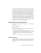
... conditions directly influences the quality of Autodesk Inventor Simulation Stress Analysis, view the online demonstrations and tutorials. Avoiding, or in the design phase can be the difference between failure and expected performance. Here is done using a mathematical representation of a physical system composed of: ■ A part or assembly (model). ■ Material properties. ■ Applicable boundary conditions (loads, supports), contact conditions, and mesh, referred...
... conditions directly influences the quality of Autodesk Inventor Simulation Stress Analysis, view the online demonstrations and tutorials. Avoiding, or in the design phase can be the difference between failure and expected performance. Here is done using a mathematical representation of a physical system composed of: ■ A part or assembly (model). ■ Material properties. ■ Applicable boundary conditions (loads, supports), contact conditions, and mesh, referred...

Getting Started Guide
Page 24
... vertices. Load Load-Specific Information Force Apply a force to a set to the normal of the face, with the force pointing to the inside of the load is uniform and acts normal to the surface at all locations on the surface. Bearing Load Moment Apply a bearing load only to faces. Cylindrical selections provide an axial direction. The following list explains the available load types. Define the...
... vertices. Load Load-Specific Information Force Apply a force to a set to the normal of the face, with the force pointing to the inside of the load is uniform and acts normal to the surface at all locations on the surface. Bearing Load Moment Apply a bearing load only to faces. Cylindrical selections provide an axial direction. The following list explains the available load types. Define the...

Getting Started Guide
Page 34
Set Results Display Options While viewing your model. No Shading Maximum Turns off the display of the point of the load symbols on the part. 28 | Chapter 3 View Results Minimum Turns on and off the display of the point of the results display for your results, you adjust the color bar display parameters. Command Used to modify the features of minimum result in the mode. Boundary Condition Turns on and off the...
Set Results Display Options While viewing your model. No Shading Maximum Turns off the display of the point of the load symbols on the part. 28 | Chapter 3 View Results Minimum Turns on and off the display of the point of the results display for your results, you adjust the color bar display parameters. Command Used to modify the features of minimum result in the mode. Boundary Condition Turns on and off the...

Getting Started Guide
Page 38
.... You must update these in it . The direction of the geometry change , even if the feature associated with the load changes orientation. Delete a load or constraint ■ In the browser, right-click a load or constraint, and then select Delete from the menu. Add a load or constraint ■ On the Stress Analysis tab, select the command and follow the same procedure you used to create your model, you...
.... You must update these in it . The direction of the geometry change , even if the feature associated with the load changes orientation. Delete a load or constraint ■ In the browser, right-click a load or constraint, and then select Delete from the menu. Add a load or constraint ■ On the Stress Analysis tab, select the command and follow the same procedure you used to create your model, you...

Getting Started Guide
Page 45
... simulation. These must be recomputed for the copied model. 39 Stress Analysis input and results information, including loads, constraints, and all Simulation files with or modify the simulation files outside of Inventor. Create and Use Analysis Files After you set up any stress analysis information in Autodesk Inventor Simulation, saving the part or assembly also saves the stress analysis information in a dedicated folder of the Mesh and Result data...
... simulation. These must be recomputed for the copied model. 39 Stress Analysis input and results information, including loads, constraints, and all Simulation files with or modify the simulation files outside of Inventor. Create and Use Analysis Files After you set up any stress analysis information in Autodesk Inventor Simulation, saving the part or assembly also saves the stress analysis information in a dedicated folder of the Mesh and Result data...
