
User Guide
Page 10
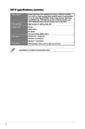
Z97-P specifications summary BIOS features Manageability Support DVD OS support Form factor 64 Mb Flash ROM, UEFI AMI BIOS, PnP, DMI 2.7, WfM 2.0, SM BIOS 2.8.0, ACPI 5.0, Multi-language BIOS, ASUS EZ Flash 2, CrashFree BIOS 3, F11 EZ Tuning Wizard, F6 Qfan Control, F3 My Favorites, Quick Note, Last Modified Log... Detect) memory information WfM 2.0, DMI 2.7, WOR by PME, PXE Drivers ASUS utilities EZ Update Anti-virus software (OEM version) Windows® 8.1, 32-bit/64-bit Windows® 8, 32-bit/64-bit Windows® 7, 32-bit/64-bit ATX form factor: 12.0 in . (30.5 cm x 21.3 cm) ...
Z97-P specifications summary BIOS features Manageability Support DVD OS support Form factor 64 Mb Flash ROM, UEFI AMI BIOS, PnP, DMI 2.7, WfM 2.0, SM BIOS 2.8.0, ACPI 5.0, Multi-language BIOS, ASUS EZ Flash 2, CrashFree BIOS 3, F11 EZ Tuning Wizard, F6 Qfan Control, F3 My Favorites, Quick Note, Last Modified Log... Detect) memory information WfM 2.0, DMI 2.7, WOR by PME, PXE Drivers ASUS utilities EZ Update Anti-virus software (OEM version) Windows® 8.1, 32-bit/64-bit Windows® 8, 32-bit/64-bit Windows® 7, 32-bit/64-bit ATX form factor: 12.0 in . (30.5 cm x 21.3 cm) ...
User Guide
Page 11
... the bag that came with the component. • Before you install or remove any component, ensure that the ATX power supply is switched off or the power cord is detached from the power supply. ASUS Z97-P 1-1 Product introduction 1 1.1 Before you proceed Take note of the following precautions before you install motherboard components or...
... the bag that came with the component. • Before you install or remove any component, ensure that the ATX power supply is switched off or the power cord is detached from the power supply. ASUS Z97-P 1-1 Product introduction 1 1.1 Before you proceed Take note of the following precautions before you install motherboard components or...
User Guide
Page 14
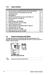
...panel connector (10-1 pin F_PANEL) 10. Clear RTC RAM (3-pin CLRTC) 11. Digital audio connector (4-1 pin SPDIF_OUT) 15. Z97-P Z97-P CPU socket LGA1150 Unplug all power cables before installing the CPU. 1-4 Chapter 1: Product introduction Serial port connector (10-1 pin...i3, Pentium® , Celeron® processors. USB 3.0 connector (20-1 pin USB3_12) 7. 1.2.4 Layout contents Connectors/Jumpers/Slots/LED 1. Intel® Z97 Serial ATA 6.0 Gb/s connectors (7-pin SATA6G_1-4) 6. Speaker connector (4-pin SPEAKER) 9. LGA1150 CPU socket 4. TPM connector (20-1 pin TPM) 13. ...
...panel connector (10-1 pin F_PANEL) 10. Clear RTC RAM (3-pin CLRTC) 11. Digital audio connector (4-1 pin SPDIF_OUT) 15. Z97-P Z97-P CPU socket LGA1150 Unplug all power cables before installing the CPU. 1-4 Chapter 1: Product introduction Serial port connector (10-1 pin...i3, Pentium® , Celeron® processors. USB 3.0 connector (20-1 pin USB3_12) 7. 1.2.4 Layout contents Connectors/Jumpers/Slots/LED 1. Intel® Z97 Serial ATA 6.0 Gb/s connectors (7-pin SATA6G_1-4) 6. Speaker connector (4-pin SPEAKER) 9. LGA1150 CPU socket 4. TPM connector (20-1 pin TPM) 13. ...
User Guide
Page 28
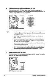
... Supply Wattage Calculator at http://support.asus. Find the proper orientation and push down firmly until the connectors completely fit. The system may become unstable or may not boot up if the power is for details. 7. SPEAKER Z97-P PIN 1 Z97-P Speaker connector 1-18 +5V GND... +5V Standby +5 Volts Power OK -5 Volts GND GND PIN 1 +5 Volts GND GND GND GND GND GND GND Z97-P +5 Volts PSON# GND GND +3 Volts -12 Volts +3 Volts +3 Volts PIN 1 Z97-P ATX power connectors • For a fully configured system, we recommend that you use a PSU with a higher power output ...
... Supply Wattage Calculator at http://support.asus. Find the proper orientation and push down firmly until the connectors completely fit. The system may become unstable or may not boot up if the power is for details. 7. SPEAKER Z97-P PIN 1 Z97-P Speaker connector 1-18 +5V GND... +5V Standby +5 Volts Power OK -5 Volts GND GND PIN 1 +5 Volts GND GND GND GND GND GND GND Z97-P +5 Volts PSON# GND GND +3 Volts -12 Volts +3 Volts +3 Volts PIN 1 Z97-P ATX power connectors • For a fully configured system, we recommend that you use a PSU with a higher power output ...
User Guide
Page 30
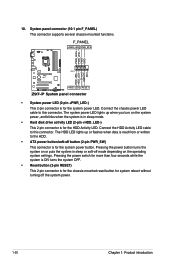
Connect the HDD Activity LED cable to this connector. RESET Z97-P System panel connector • System power LED (2-pin +PWR_LED-) This 2-pin connector is for the HDD Activity LED. The HDD LED lights up when you ... without turning off button (2-pin PWR_SW) This connector is read from or written to this connector. Ground HWRST# (NC) Z97-P PIN 1 +HDD_LED- Connect the chassis power LED cable to the HDD. • ATX power button/soft-off the system power. 1-20 Chapter 1: Product introduction System panel connector (10-1 pin F_PANEL) This connector...
Connect the HDD Activity LED cable to this connector. RESET Z97-P System panel connector • System power LED (2-pin +PWR_LED-) This 2-pin connector is for the HDD Activity LED. The HDD LED lights up when you ... without turning off button (2-pin PWR_SW) This connector is read from or written to this connector. Ground HWRST# (NC) Z97-P PIN 1 +HDD_LED- Connect the chassis power LED cable to the HDD. • ATX power button/soft-off the system power. 1-20 Chapter 1: Product introduction System panel connector (10-1 pin F_PANEL) This connector...
User Guide
Page 71
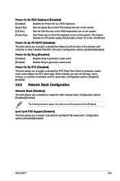
... [Disabled] [Enabled] 2.6.9 Network Stack Configuration Network Stack [Disabled] This item allows user to generate a wake event. This feature requires an ATX power supply that provides at least 1A on the system. Configuration options: [Disabled] [Enabled] The following two items appear only when you set... an RTC alarm date. Ipv4 / Ipv6 PXE Support [Enabled] This item allows you to [Enabled]. Configuration options: [Disabled] [Enabled] ASUS Z97-P 2-39 Power On By RTC [Disabled] This item allows you can set the previous item to enable or disable the Wake-on-LAN function...
... [Disabled] [Enabled] 2.6.9 Network Stack Configuration Network Stack [Disabled] This item allows user to generate a wake event. This feature requires an ATX power supply that provides at least 1A on the system. Configuration options: [Disabled] [Enabled] The following two items appear only when you set... an RTC alarm date. Ipv4 / Ipv6 PXE Support [Enabled] This item allows you to [Enabled]. Configuration options: [Disabled] [Enabled] ASUS Z97-P 2-39 Power On By RTC [Disabled] This item allows you can set the previous item to enable or disable the Wake-on-LAN function...


