

User Guide
Page 4
Contents Chapter 3: BIOS setup 3.1 Knowing BIOS 3-1 3.2 BIOS setup program 3-2 3.2.1 EZ Mode 3-3 3.2.2 Advanced Mode 3-4 3.2.3 QFan Control 3-7 3.2.4 EZ Tuning Wizard 3-9 3.3 My Favorites 3-11 3.4 Main menu 3-13 3.5 ... 3-44 3.8 Boot menu 3-48 3.9 Tool menu 3-54 3.9.1 ASUS EZ Flash 2 Utility 3-54 3.9.2 ASUS Overclocking Profile 3-55 3.9.3 ASUS SPD Information 3-56 3.10 Exit menu 3-57 3.11 Updating BIOS 3-58 3.11.1 EZ Update 3-58 3.11.2 ASUS EZ Flash 2 3-59 3.11.3 ASUS CrashFree BIOS 3 3-60 Chapter 4: Software support 4.1 Installing an operating system ...
Contents Chapter 3: BIOS setup 3.1 Knowing BIOS 3-1 3.2 BIOS setup program 3-2 3.2.1 EZ Mode 3-3 3.2.2 Advanced Mode 3-4 3.2.3 QFan Control 3-7 3.2.4 EZ Tuning Wizard 3-9 3.3 My Favorites 3-11 3.4 Main menu 3-13 3.5 ... 3-44 3.8 Boot menu 3-48 3.9 Tool menu 3-54 3.9.1 ASUS EZ Flash 2 Utility 3-54 3.9.2 ASUS Overclocking Profile 3-55 3.9.3 ASUS SPD Information 3-56 3.10 Exit menu 3-57 3.11 Updating BIOS 3-58 3.11.1 EZ Update 3-58 3.11.2 ASUS EZ Flash 2 3-59 3.11.3 ASUS CrashFree BIOS 3 3-60 Chapter 4: Software support 4.1 Installing an operating system ...

User Guide
Page 5
... 4.4.8 System Information 4-18 4.4.9 Version 4-19 4.5 Audio configurations 4-20 Chapter 5: RAID support 5.1 RAID configurations 5-1 5.1.1 RAID definitions 5-1 5.1.2 Installing Serial ATA hard disks 5-2 5.1.3 Setting the RAID item in BIOS 5-2 5.1.4 Intel® Rapid Storage Technology Option ROM utility 5-3 5.2 Creating a RAID driver disk 5-7 5.2.1 Creating a RAID driver disk without entering the OS 5-7 5.2.2 Creating a RAID driver disk in...
... 4.4.8 System Information 4-18 4.4.9 Version 4-19 4.5 Audio configurations 4-20 Chapter 5: RAID support 5.1 RAID configurations 5-1 5.1.1 RAID definitions 5-1 5.1.2 Installing Serial ATA hard disks 5-2 5.1.3 Setting the RAID item in BIOS 5-2 5.1.4 Intel® Rapid Storage Technology Option ROM utility 5-3 5.2 Creating a RAID driver disk 5-7 5.2.1 Creating a RAID driver disk without entering the OS 5-7 5.2.2 Creating a RAID driver disk in...

User Guide
Page 7
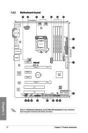
... when installing system components. 3. These documents are also provided. 4. Chapter 1: Product introduction This chapter describes the features of the BIOS parameters are not part of the switches, jumpers, and connectors on ASUS hardware and software products. 2. About this guide is organized This guide contains the following sources for additional information and for...
... when installing system components. 3. These documents are also provided. 4. Chapter 1: Product introduction This chapter describes the features of the BIOS parameters are not part of the switches, jumpers, and connectors on ASUS hardware and software products. 2. About this guide is organized This guide contains the following sources for additional information and for...

User Guide
Page 10
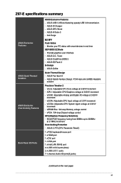
...up popping noise to 10Gb/s data-transfer speeds ASUS Fan Xpert3 - Short circuit damage prevention - ASUS ESD Guards - ASUS Stainless Steel Back I/O - 3x more durable corrosion-resistant coating UEFI BIOS - The latest transfer technologies with the most ...-detection, multi-streaming, and front panel jack-retasking High Performance ASUS 5X PROTECTION - ASUS DIGI+ VRM - 6 Phase digital power design - Enhanced ESD protection - Z97-E specifications summary USB Audio ASUS Exclusive Features Intel® Z97 Express Chipset - supports ASUS USB 3.0 Boost - 6 x USB 3.0/2.0 ports (2 ports at...
...up popping noise to 10Gb/s data-transfer speeds ASUS Fan Xpert3 - Short circuit damage prevention - ASUS ESD Guards - ASUS Stainless Steel Back I/O - 3x more durable corrosion-resistant coating UEFI BIOS - The latest transfer technologies with the most ...-detection, multi-streaming, and front panel jack-retasking High Performance ASUS 5X PROTECTION - ASUS DIGI+ VRM - 6 Phase digital power design - Enhanced ESD protection - Z97-E specifications summary USB Audio ASUS Exclusive Features Intel® Z97 Express Chipset - supports ASUS USB 3.0 Boost - 6 x USB 3.0/2.0 ports (2 ports at...
User Guide
Page 11
... PC status with smart devices in real time UEFI BIOS EZ Mode - Friendly graphics user interface - ASUS Fan Xpert 3 - vCore: Adjustable CPU Core voltage at 0.001V increment - ASUS USB 3.0 Boost featuring speedy USB 3.0 transmission - Anti... 7.1-channel Audio I /O Ports ASUS Exclusive Features - Z97-E specifications summary ASUS Exclusive Features ASUS Quiet Thermal Solution ASUS Exclusive Overclocking Features Back Panel I /O ports(6-jacks) (continued on the next page) xi ASUS GPU Boost - ASUS O.C. vDRAM Bus: 124-step Memory voltage control - ASUS AI Charger - vCCSA: Adjustable...
... PC status with smart devices in real time UEFI BIOS EZ Mode - Friendly graphics user interface - ASUS Fan Xpert 3 - vCore: Adjustable CPU Core voltage at 0.001V increment - ASUS USB 3.0 Boost featuring speedy USB 3.0 transmission - Anti... 7.1-channel Audio I /O Ports ASUS Exclusive Features - Z97-E specifications summary ASUS Exclusive Features ASUS Quiet Thermal Solution ASUS Exclusive Overclocking Features Back Panel I /O ports(6-jacks) (continued on the next page) xi ASUS GPU Boost - ASUS O.C. vDRAM Bus: 124-step Memory voltage control - ASUS AI Charger - vCCSA: Adjustable...
User Guide
Page 12
xii Z97-E specifications summary Internal I/O Connectors BIOS Manageability Support DVD Operating system support Form factor 1 x USB 3.0/2.0 connectors support additional 2 USB ports (19-pin) 3 x USB 2.0/1/1 connectors support additional 6 USB ports 1 x ...x 8.6 in. (30.5 cm x 21.8cm) Specifications are subject to the control mode automatically. 64 Mb Flash ROM, UEFI AMI BIOS, PnP, DMI2.7, WfM2.0, SM BIOS 2.8, ACPI 5.0, Multi-language BIOS, ASUS EZ Flash 2, CrashFree BIOS 3, F6 Qfan Control, F11 EZ Tuning Wizard, F3 My Favorites & Shortcut, Quick Note, Last Modified log, F12 PrintScreen, and...
xii Z97-E specifications summary Internal I/O Connectors BIOS Manageability Support DVD Operating system support Form factor 1 x USB 3.0/2.0 connectors support additional 2 USB ports (19-pin) 3 x USB 2.0/1/1 connectors support additional 6 USB ports 1 x ...x 8.6 in. (30.5 cm x 21.8cm) Specifications are subject to the control mode automatically. 64 Mb Flash ROM, UEFI AMI BIOS, PnP, DMI2.7, WfM2.0, SM BIOS 2.8, ACPI 5.0, Multi-language BIOS, ASUS EZ Flash 2, CrashFree BIOS 3, F6 Qfan Control, F11 EZ Tuning Wizard, F3 My Favorites & Shortcut, Quick Note, Last Modified log, F12 PrintScreen, and...
User Guide
Page 18
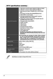
... 1 2 2 30.5cm(12.0in) USB3_12 EATXPWR SATAEXPRESS SATA6G_6 SATA6G_5 AUDIO Intel® I218-V ASM 1083 CHA_FAN1 PCIEX1_1 Z97-E PCIEX16_1 PCIEX1_2 PCIEX1_3 BATTERY M.2(SOCKET3) 7 Intel® Z97 Super I/O ALC 892 SPDIF_OUT AAFP PCIEX16_2 PCI1 64Mb BIOS PCI2 COM TPM SB_PWR CLRTC USB910 USB1112 USB1314 PANEL SATA6G_1 SATA6G_3 SATA6G_2 SATA6G_4 8 16 15 14 13 12...
... 1 2 2 30.5cm(12.0in) USB3_12 EATXPWR SATAEXPRESS SATA6G_6 SATA6G_5 AUDIO Intel® I218-V ASM 1083 CHA_FAN1 PCIEX1_1 Z97-E PCIEX16_1 PCIEX1_2 PCIEX1_3 BATTERY M.2(SOCKET3) 7 Intel® Z97 Super I/O ALC 892 SPDIF_OUT AAFP PCIEX16_2 PCI1 64Mb BIOS PCI2 COM TPM SB_PWR CLRTC USB910 USB1112 USB1314 PANEL SATA6G_1 SATA6G_3 SATA6G_2 SATA6G_4 8 16 15 14 13 12...

User Guide
Page 22
...on the CPU's capabilities and other installed devices. • Always install the DIMMS with the vendor to get the correct memory modules. • ASUS exclusively provides hyper DIMM support function. • Hyper DIMM support is not the JEDEC memory standard. or D.O.C.P. Any excess memory from a memory module...not support DIMMs made up of 512 Mb (64 MB) chips or less (Memory chip capacity counts in the BIOS for the hyper DIMM support. • Visit the ASUS website for the latest QVL. c) For more efficient memory cooling system to the physical characteristics of individual CPUs. ...
...on the CPU's capabilities and other installed devices. • Always install the DIMMS with the vendor to get the correct memory modules. • ASUS exclusively provides hyper DIMM support function. • Hyper DIMM support is not the JEDEC memory standard. or D.O.C.P. Any excess memory from a memory module...not support DIMMs made up of 512 Mb (64 MB) chips or less (Memory chip capacity counts in the BIOS for the hyper DIMM support. • Visit the ASUS website for the latest QVL. c) For more efficient memory cooling system to the physical characteristics of individual CPUs. ...
User Guide
Page 25
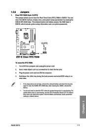
.... The onboard button cell battery powers the RAM data in CMOS. Shut down the key during the boot process and enter BIOS setup to re- 1.2.6 Jumpers 1. Plug the power cord and turn ON the computer. 4. Hold down and reboot the system, then the... BIOS automatically resets parameter settings to overclocking, use the CPU Parameter Recall (C.P.R.) feature. Z97-E CLRTC +3V_BAT GND PIN 1 Z97-E Clear RTC RAM To erase the RTC RAM: 1. Turn OFF the computer and unplug the power cord. 2. Chapter 1 ASUS Z97-E 1-11 Clear RTC RAM (2-pin CLRTC) ...
.... The onboard button cell battery powers the RAM data in CMOS. Shut down the key during the boot process and enter BIOS setup to re- 1.2.6 Jumpers 1. Plug the power cord and turn ON the computer. 4. Hold down and reboot the system, then the... BIOS automatically resets parameter settings to overclocking, use the CPU Parameter Recall (C.P.R.) feature. Z97-E CLRTC +3V_BAT GND PIN 1 Z97-E Clear RTC RAM To erase the RTC RAM: 1. Turn OFF the computer and unplug the power cord. 2. Chapter 1 ASUS Z97-E 1-11 Clear RTC RAM (2-pin CLRTC) ...
User Guide
Page 28
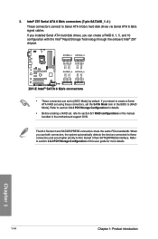
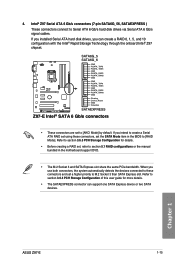
...introduction If you can create a RAID 0, 1, 5, and 10 configuration with the Intel® Rapid Storage Technology through the onboard Intel® Z97 chipset. Intel® Z97 Serial ATA 6 Gb/s connectors (7-pin SATA6G_1~4 ) These connectors connect to [RAID Mode]. The M.2 Socket 3 and SATAEXPRESS connectors share the... ATA RAID set using these connectors and set the SATA Mode item in the motherboard support DVD. SATA6G_1 SATA6G_3 Z97-E SATA6G_2 SATA6G_4 Z97-E Intel® SATA 6 Gb/s connectors • These connectors are set , refer to section 5.1 RAID configurations or the manual...
...introduction If you can create a RAID 0, 1, 5, and 10 configuration with the Intel® Rapid Storage Technology through the onboard Intel® Z97 chipset. Intel® Z97 Serial ATA 6 Gb/s connectors (7-pin SATA6G_1~4 ) These connectors connect to [RAID Mode]. The M.2 Socket 3 and SATAEXPRESS connectors share the... ATA RAID set using these connectors and set the SATA Mode item in the motherboard support DVD. SATA6G_1 SATA6G_3 Z97-E SATA6G_2 SATA6G_4 Z97-E Intel® SATA 6 Gb/s connectors • These connectors are set , refer to section 5.1 RAID configurations or the manual...
User Guide
Page 29
... and 10 configuration with the Intel® Rapid Storage Technology through the onboard Intel® Z97 chipset. When you can support one SATA Express device or two SATA devices. Chapter 1 ASUS Z97-E 1-15 If you installed Serial ATA hard disk drives, you use both connectors, the system... automatically detects the devices connected to these connectors, set , refer to section 5.1 RAID configurations or the manual bundled in the BIOS to section 3.6.3 PCH...
... and 10 configuration with the Intel® Rapid Storage Technology through the onboard Intel® Z97 chipset. When you can support one SATA Express device or two SATA devices. Chapter 1 ASUS Z97-E 1-15 If you installed Serial ATA hard disk drives, you use both connectors, the system... automatically detects the devices connected to these connectors, set , refer to section 5.1 RAID configurations or the manual bundled in the BIOS to section 3.6.3 PCH...

User Guide
Page 30
... motherboard's high-definition audio capability. • If you connect a high-definition front panel audio module to avail of the system chassis. +5V SPDIFOUT GND Z97-E PIN 1 SPDIF_OUT Z97-E Digital audio connector The S/PDIF module is purchased separately. 6. Digital audio connector (4-1 pin SPDIF_OUT) This connector is for an additional Sony/Philips Digital Interface... you want to connect a high-definition or an AC'97 front panel audio module to this connector, set the Front Panel Type item in the BIOS setup to [HD] or [AC97]. 1-16 Chapter 1: Product introduction Chapter 1
... motherboard's high-definition audio capability. • If you connect a high-definition front panel audio module to avail of the system chassis. +5V SPDIFOUT GND Z97-E PIN 1 SPDIF_OUT Z97-E Digital audio connector The S/PDIF module is purchased separately. 6. Digital audio connector (4-1 pin SPDIF_OUT) This connector is for an additional Sony/Philips Digital Interface... you want to connect a high-definition or an AC'97 front panel audio module to this connector, set the Front Panel Type item in the BIOS setup to [HD] or [AC97]. 1-16 Chapter 1: Product introduction Chapter 1
User Guide
Page 33
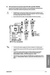
...and PWM modes. These are not jumpers! To configure the CPU fan's control mode, go to Advanced Mode > Monitor > CPU Q-Fan Control item in BIOS. Chapter 1 ASUS Z97-E 1-19 Insufficient air flow inside the system may damage the motherboard components. A B CPU_FAN CHA_FAN2 A B C CPU FAN PWM CPU FAN IN CPU FAN...FAN PWM CHA FAN PWM CHA FAN IN CHA FAN PWR GND Z97-E Fan connectors • The CPU_FAN connector supports the CPU fan of maximum 1A (12W) fan power. • The CPU_FAN connector and CHA_FAN connectors support the ASUS FAN Xpert 3 feature. • The CPU fan connector detects ...
...and PWM modes. These are not jumpers! To configure the CPU fan's control mode, go to Advanced Mode > Monitor > CPU Q-Fan Control item in BIOS. Chapter 1 ASUS Z97-E 1-19 Insufficient air flow inside the system may damage the motherboard components. A B CPU_FAN CHA_FAN2 A B C CPU FAN PWM CPU FAN IN CPU FAN...FAN PWM CHA FAN PWM CHA FAN IN CHA FAN PWR GND Z97-E Fan connectors • The CPU_FAN connector supports the CPU fan of maximum 1A (12W) fan power. • The CPU_FAN connector and CHA_FAN connectors support the ASUS FAN Xpert 3 feature. • The CPU fan connector detects ...

User Guide
Page 48
...; Due to the design of the Intel® 9 series chipset, all USB devices connected to three displays under Windows® OS environment, two displays under BIOS, and one display under DOS. • Intel display architecture design supports the following maximum supported pixel clocks (Pixel Clock = H total x V Total x Frame Rate (Fresh screen...
...; Due to the design of the Intel® 9 series chipset, all USB devices connected to three displays under Windows® OS environment, two displays under BIOS, and one display under DOS. • Intel display architecture design supports the following maximum supported pixel clocks (Pixel Clock = H total x V Total x Frame Rate (Fresh screen...
User Guide
Page 51
... may light up or change from the time you press the ATX power button. At power on the BIOS setting. Follow the instructions in the following order: a. Chapter 2 ASUS Z97-E 2-15 For systems with a surge protector. 5. If your retailer for more than four seconds to the... power connector at the back of the BIOS setting. System power 6. 2.3 Starting up for less than four seconds to a ...
... may light up or change from the time you press the ATX power button. At power on the BIOS setting. Follow the instructions in the following order: a. Chapter 2 ASUS Z97-E 2-15 For systems with a surge protector. 5. If your retailer for more than four seconds to the... power connector at the back of the BIOS setting. System power 6. 2.3 Starting up for less than four seconds to a ...

User Guide
Page 53
... that requires further BIOS settings or update. The term "BIOS" in the motherboard CMOS. Inappropriate BIOS settings may result to ensure optimal performance. In normal circumstances, the default BIOS settings apply to most conditions to instability or boot failure. Chapter 3 ASUS Z97-E 3-1 BIOS (Basic Input and... Output System) stores system hardware settings such as Z97E.CAP for system startup in this user manual refers to run the BIOS Setup. • You have installed a new system...
... that requires further BIOS settings or update. The term "BIOS" in the motherboard CMOS. Inappropriate BIOS settings may result to ensure optimal performance. In normal circumstances, the default BIOS settings apply to most conditions to instability or boot failure. Chapter 3 ASUS Z97-E 3-1 BIOS (Basic Input and... Output System) stores system hardware settings such as Z97E.CAP for system startup in this user manual refers to run the BIOS Setup. • You have installed a new system...

User Guide
Page 54
... three options, press key to enter BIOS. • The BIOS setup screens shown in using the first two options. 3.2 BIOS setup program Use the BIOS Setup to update the BIOS or configure its routines. Entering BIOS Setup after POST To enter BIOS Setup after changing any BIOS setting, load the default settings to...not press or , POST continues with its parameters. If you failed to erase the RTC RAM via the Clear CMOS jumper. • The BIOS setup program does not support the Bluetooth devices. See section 3.10 Exit Menu for details. • If the system fails to boot after ...
... three options, press key to enter BIOS. • The BIOS setup screens shown in using the first two options. 3.2 BIOS setup program Use the BIOS Setup to update the BIOS or configure its routines. Entering BIOS Setup after POST To enter BIOS Setup after changing any BIOS setting, load the default settings to...not press or , POST continues with its parameters. If you failed to erase the RTC RAM via the Clear CMOS jumper. • The BIOS setup program does not support the Bluetooth devices. See section 3.10 Exit Menu for details. • If the system fails to boot after ...
User Guide
Page 55
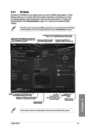
... the system Displays the Advanced mode menus Selects the boot device priority The boot device options vary depending on the devices you enter the BIOS setup program. ASUS Z97-E 3-3 Click < or > to the Setup Mode item in section 3.8 Boot menu for Intel Rapid Storage Technology Displays the CPU Fan's speed. Refer to switch...
... the system Displays the Advanced mode menus Selects the boot device priority The boot device options vary depending on the devices you enter the BIOS setup program. ASUS Z97-E 3-3 Click < or > to the Setup Mode item in section 3.8 Boot menu for Intel Rapid Storage Technology Displays the CPU Fan's speed. Refer to switch...

User Guide
Page 56
... Goes back to Advanced Mode, click Advanced Mode F7 or press F7 hotkey. Refer to the following sections for experienced end-users to configure the BIOS settings. To switch from EZ Mode to EZ Mode Displays the CPU/motherboard temperature, CPU and memory voltage output 3-4 Chapter...
... Goes back to Advanced Mode, click Advanced Mode F7 or press F7 hotkey. Refer to the following sections for experienced end-users to configure the BIOS settings. To switch from EZ Mode to EZ Mode Displays the CPU/motherboard temperature, CPU and memory voltage output 3-4 Chapter...

User Guide
Page 57
... to MyFavorites menu. Refer to display in a Tree Map setup. It also allows you want to section 3.3 My Favorites for your BIOS. Refer to your system. Chapter 3 ASUS Z97-E 3-5 To display the submenu, select the item and press . Menu bar The menu bar on any menu screen means that the... item has a submenu. Select frequentlyused BIOS settings and save it to RAID mode. Q-Fan Control (F6) This button above the menu bar ...
... to MyFavorites menu. Refer to display in a Tree Map setup. It also allows you want to section 3.3 My Favorites for your BIOS. Refer to your system. Chapter 3 ASUS Z97-E 3-5 To display the submenu, select the item and press . Menu bar The menu bar on any menu screen means that the... item has a submenu. Select frequentlyused BIOS settings and save it to RAID mode. Q-Fan Control (F6) This button above the menu bar ...


