User Guide
Page 16
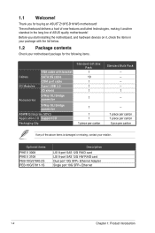
... technologies, making it , check the items in the long line of the above items is damaged or missing, contact your motherboard package for buying an ASUS® Z10PE-D16 WS motherboard! 1.1 Welcome! Thank you start installing the motherboard, and hardware devices on it another standout in your package with bracket Cables SATA 6G cable...
... technologies, making it , check the items in the long line of the above items is damaged or missing, contact your motherboard package for buying an ASUS® Z10PE-D16 WS motherboard! 1.1 Welcome! Thank you start installing the motherboard, and hardware devices on it another standout in your package with bracket Cables SATA 6G cable...

User Guide
Page 17
...Also, Intel's new microarchitecture doubles the cache bandwidth at L1/L2 to support higher FLOPS and contributes to your problems. Z10PE-D16 WS xxS1xxxxxxxx Made in signal and image processing applications. Intel® AVX 2.0 Intel® AVX 2.0 extends 256-bit ... next-generation processor power management. Next Generation of Energy Efficient Turbo, Uncore Frequency Scaling, and Per-Core P-state. ASUS Z10PE-D16 WS 1-3 Also, the Integrated Voltage Regulator enables generational performance and power improvements that reduces memory power demand and provides improved ...
...Also, Intel's new microarchitecture doubles the cache bandwidth at L1/L2 to support higher FLOPS and contributes to your problems. Z10PE-D16 WS xxS1xxxxxxxx Made in signal and image processing applications. Intel® AVX 2.0 Intel® AVX 2.0 extends 256-bit ... next-generation processor power management. Next Generation of Energy Efficient Turbo, Uncore Frequency Scaling, and Per-Core P-state. ASUS Z10PE-D16 WS 1-3 Also, the Integrated Voltage Regulator enables generational performance and power improvements that reduces memory power demand and provides improved ...

User Guide
Page 19
..., aeronautics, audio and video design applications. If a workstation is behaving abnormally, plug a flash drive into the drive. ASUS Dr. Power ASUS Dr. Power detects any relevant power issues to ensure quiet, cool, and efficient operation. Q-Code Logger Q-Code Logger is... power can easily run even the most reliable graphics performance ever. Additionally, this motherboard. ASUS Z10PE-D16 WS 1-5 1.4.2 Innovative ASUS features ASUS Fan Speed control technology The ASUS Fan Speed control technology smartly adjusts the fan speeds according to the system loading to prevent...
..., aeronautics, audio and video design applications. If a workstation is behaving abnormally, plug a flash drive into the drive. ASUS Dr. Power ASUS Dr. Power detects any relevant power issues to ensure quiet, cool, and efficient operation. Q-Code Logger Q-Code Logger is... power can easily run even the most reliable graphics performance ever. Additionally, this motherboard. ASUS Z10PE-D16 WS 1-5 1.4.2 Innovative ASUS features ASUS Fan Speed control technology The ASUS Fan Speed control technology smartly adjusts the fan speeds according to the system loading to prevent...

User Guide
Page 23
.... To optimize the motherboard features, we highly recommend that you install it in the correct orientation. Place this side towards the rear of the chassis ASUS Z10PE-D16 WS 2-3
.... To optimize the motherboard features, we highly recommend that you install it in the correct orientation. Place this side towards the rear of the chassis ASUS Z10PE-D16 WS 2-3

User Guide
Page 25
... controller setting (VGA_SW1) 3. RAID selection jumper setting (3-pin RAID_SEL1) 5. DDR4 sockets 3. PMBus 1.2 PSU select jumper (3-pin SMART_PSU1) Page 2-28 2-29 2-29 2-30 2-30 2-31 2-31 ASUS Z10PE-D16 WS 2-5 Reset button 3. Location LED (LOCLED2) 4. CATT LED (CATTERR_LED1) 5. ME firmware force recovery setting (3-pin ME_RCVR1) 6. CPU sockets 2. Baseboard Management Controller LED (BMC_LED1) 3. M2 LED (M2_LED...
... controller setting (VGA_SW1) 3. RAID selection jumper setting (3-pin RAID_SEL1) 5. DDR4 sockets 3. PMBus 1.2 PSU select jumper (3-pin SMART_PSU1) Page 2-28 2-29 2-29 2-30 2-30 2-31 2-31 ASUS Z10PE-D16 WS 2-5 Reset button 3. Location LED (LOCLED2) 4. CATT LED (CATTERR_LED1) 5. ME firmware force recovery setting (3-pin ME_RCVR1) 6. CPU sockets 2. Baseboard Management Controller LED (BMC_LED1) 3. M2 LED (M2_LED...
User Guide
Page 27
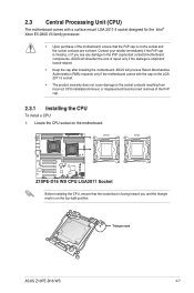
Triangle mark ASUS Z10PE-D16 WS 2-7 2.3 Central Processing Unit (CPU) The motherboard comes with the cap on the motherboard. Before installing the CPU, ensure that the PnP cap is on the ... 2011-3 socket. • The product warranty does not cover damage to the PnP cap/socket contacts/motherboard components. ASUS will shoulder the cost of the PnP cap. 2.3.1 Installing the CPU To install a CPU: 1. ASUS will process Return Merchandise Authorization (RMA) requests only if the motherboard comes with a surface mount LGA 2011-3 socket...
Triangle mark ASUS Z10PE-D16 WS 2-7 2.3 Central Processing Unit (CPU) The motherboard comes with the cap on the motherboard. Before installing the CPU, ensure that the PnP cap is on the ... 2011-3 socket. • The product warranty does not cover damage to the PnP cap/socket contacts/motherboard components. ASUS will shoulder the cost of the PnP cap. 2.3.1 Installing the CPU To install a CPU: 1. ASUS will process Return Merchandise Authorization (RMA) requests only if the motherboard comes with a surface mount LGA 2011-3 socket...

User Guide
Page 29
... not insert the load lever into the slot. Install the CPU into the retention tab. The CPU fits in only one correct orientation. Triangle mark ASUS Z10PE-D16 WS 2-9 4. Push the left load lever to prevent bending the CPU pins on the socket box. 8. Load plate 6. Do not force to let it may damage...
... not insert the load lever into the slot. Install the CPU into the retention tab. The CPU fits in only one correct orientation. Triangle mark ASUS Z10PE-D16 WS 2-9 4. Push the left load lever to prevent bending the CPU pins on the socket box. 8. Load plate 6. Do not force to let it may damage...

User Guide
Page 31
Connect the CPU fan cable to connect the CPU fan connector! ASUS Z10PE-D16 WS 2-11 DO NOT forget to the connector on the motherboard labeled CPU_FAN1 / CPU_FAN2. DO NOT eat it off immediately, and seek professional medical help. 13. ...
Connect the CPU fan cable to connect the CPU fan connector! ASUS Z10PE-D16 WS 2-11 DO NOT forget to the connector on the motherboard labeled CPU_FAN1 / CPU_FAN2. DO NOT eat it off immediately, and seek professional medical help. 13. ...

User Guide
Page 33
... (CPU2) A2 A1 B2 B1 C2 C1 D2 D1 E2 E1 F2 F1 G2 G1 H2 H1 2 DIMMs P P 4 DIMMs P P P P 8 DIMMs P P P P P P P P 12 DIMMs P P P P P PPPPP P P 16 DIMMs P P P P P P P P P P P P P P P P ASUS Z10PE-D16 WS 2-13 Single CPU configuration You can refer to the following recommended memory population for a single CPU configuration. Single CPU configuration (must be installed on CPU1...
... (CPU2) A2 A1 B2 B1 C2 C1 D2 D1 E2 E1 F2 F1 G2 G1 H2 H1 2 DIMMs P P 4 DIMMs P P P P 8 DIMMs P P P P P P P P 12 DIMMs P P P P P PPPPP P P 16 DIMMs P P P P P P P P P P P P P P P P ASUS Z10PE-D16 WS 2-13 Single CPU configuration You can refer to the following recommended memory population for a single CPU configuration. Single CPU configuration (must be installed on CPU1...
User Guide
Page 35
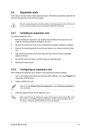
... earlier. 6. Replace the system cover. 2.5.2 Configuring an expansion card After installing the expansion card, configure it and make the necessary hardware settings for the card. 2. ASUS Z10PE-D16 WS 2-15 Keep the screw for more information. 3. Refer to the chassis with the slot and press firmly until the card is already installed in section...
... earlier. 6. Replace the system cover. 2.5.2 Configuring an expansion card After installing the expansion card, configure it and make the necessary hardware settings for the card. 2. ASUS Z10PE-D16 WS 2-15 Keep the screw for more information. 3. Refer to the chassis with the slot and press firmly until the card is already installed in section...

User Guide
Page 37
Motherboard Layout PCIE 1 PCIE 2 PCIE 3 PCIE 4 PCIE 5 PCIE 6 1 x PCIE x16 (x8 Gen3 Link) 1 x PCIE X16 (x16 Gen3 Link) 1 x PCIE x16 (x8 Gen3 Link) 1 x PCIE X16 (x16 Gen3 Link) 1 x PCIE x16 (x16 Gen3 Link) 1x PCIE x16 (x16 Gen3 Link) ASUS Z10PE-D16 WS 2-17
Motherboard Layout PCIE 1 PCIE 2 PCIE 3 PCIE 4 PCIE 5 PCIE 6 1 x PCIE x16 (x8 Gen3 Link) 1 x PCIE X16 (x16 Gen3 Link) 1 x PCIE x16 (x8 Gen3 Link) 1 x PCIE X16 (x16 Gen3 Link) 1 x PCIE x16 (x16 Gen3 Link) 1x PCIE x16 (x16 Gen3 Link) ASUS Z10PE-D16 WS 2-17
User Guide
Page 39
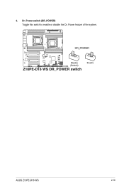
Dr. Power switch (DR_POWER) Toggle this switch to enable or disable the Dr. Power feature of the system. 3. ASUS Z10PE-D16 WS 2-19
Dr. Power switch (DR_POWER) Toggle this switch to enable or disable the Dr. Power feature of the system. 3. ASUS Z10PE-D16 WS 2-19
User Guide
Page 41
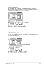
ASUS Z10PE-D16 WS 2-21 Location LED (LOCLED2) This onboard LED lights up when the Location button on a server rack. 4. The Location LED helps visually locate and quickly identify the server in error on the server is pressed or when triggered by a system management software. 3. CATT LED (CATTERR_LED1) The CATT LED indicates that the system has experienced a fatal or catastrophic error and cannot continue to operate.
ASUS Z10PE-D16 WS 2-21 Location LED (LOCLED2) This onboard LED lights up when the Location button on a server rack. 4. The Location LED helps visually locate and quickly identify the server in error on the server is pressed or when triggered by a system management software. 3. CATT LED (CATTERR_LED1) The CATT LED indicates that the system has experienced a fatal or catastrophic error and cannot continue to operate.

User Guide
Page 43
ASUS Z10PE-D16 WS 2-23 ASUS Dr. Power LED (PGLED3) This LED near the Dr. Power switch lights up when the Dr. Power switch is on Enable. 7.
ASUS Z10PE-D16 WS 2-23 ASUS Dr. Power LED (PGLED3) This LED near the Dr. Power switch lights up when the Dr. Power switch is on Enable. 7.
User Guide
Page 45
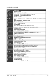
... capsule is not found Invalid recovery capsule Reserved for future AMI error codes DXE Core is started NVRAM initialization Installation of the PCH Runtime Services ASUS Z10PE-D16 WS 2-25 EF F0 F1 F2 F3 F4 F5 -
... capsule is not found Invalid recovery capsule Reserved for future AMI error codes DXE Core is started NVRAM initialization Installation of the PCH Runtime Services ASUS Z10PE-D16 WS 2-25 EF F0 F1 F2 F3 F4 F5 -
User Guide
Page 47
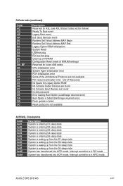
... the S2 sleep state System is waking up from the S4 sleep state System has transitioned into ACPI mode. System has transitioned into ACPI mode. ASUS Z10PE-D16 WS 2-27 Q-Code table (continued) Code AC AD AE AF B0 B1 B2 B3 B4 B5 B6 B7 B8- BF D0 D1 D2 D3 D4 D5...
... the S2 sleep state System is waking up from the S4 sleep state System has transitioned into ACPI mode. System has transitioned into ACPI mode. ASUS Z10PE-D16 WS 2-27 Q-Code table (continued) Code AC AD AE AF B0 B1 B2 B3 B4 B5 B6 B7 B8- BF D0 D1 D2 D3 D4 D5...

User Guide
Page 49
Set to pins 1-2 to disable the onboard VGA controller. 2. VGA controller setting (VGA_SW1) This jumper allows you to select the connection to BMC or PHC for PCIE 1/3/5/7 SMBUS. SMBUS connection setting (TESLA_M_SW) This jumper allows you to enable to activate the VGA feature. 3. ASUS Z10PE-D16 WS 2-29
Set to pins 1-2 to disable the onboard VGA controller. 2. VGA controller setting (VGA_SW1) This jumper allows you to select the connection to BMC or PHC for PCIE 1/3/5/7 SMBUS. SMBUS connection setting (TESLA_M_SW) This jumper allows you to enable to activate the VGA feature. 3. ASUS Z10PE-D16 WS 2-29

User Guide
Page 53
... configuration Port Light Blue Lime Pink Orange Black Gray Headset 2-channel Line In Line Out Mic In - - - 4-channel Line In Front Speaker Out Mic In - ASUS Z10PE-D16 WS 2-33 Rear Speaker Out - 6-channel Line In Front Speaker Out Mic In Center/Subwoofer Rear Speaker Out Side Speaker Out* 8-channel Line In Front Speaker...
... configuration Port Light Blue Lime Pink Orange Black Gray Headset 2-channel Line In Line Out Mic In - - - 4-channel Line In Front Speaker Out Mic In - ASUS Z10PE-D16 WS 2-33 Rear Speaker Out - 6-channel Line In Front Speaker Out Mic In Center/Subwoofer Rear Speaker Out Side Speaker Out* 8-channel Line In Front Speaker...

User Guide
Page 55
... connected to the SATA or SAS add-on card causes the front panel LED to light up to the SATA or SAS add-on card. ASUS Z10PE-D16 WS 2-35 These USB connectors comply with USB 2.0 specification that supports up . 2. The read or write activities of the system chassis. Hard disk activity LED connector...
... connected to the SATA or SAS add-on card causes the front panel LED to light up to the SATA or SAS add-on card. ASUS Z10PE-D16 WS 2-35 These USB connectors comply with USB 2.0 specification that supports up . 2. The read or write activities of the system chassis. Hard disk activity LED connector...

User Guide
Page 57
Serial port connectors (10-1 pin COM1) These connectors are for low-speed system management communications. 6. Power supply SMBus connector (PSUSMB1) This connector supplies power for the serial (COM) port. Connect the serial port module cable to one of these connectors, then install the module to a slot opening at the back of the system chassis. ASUS Z10PE-D16 WS 2-37 5.
Serial port connectors (10-1 pin COM1) These connectors are for low-speed system management communications. 6. Power supply SMBus connector (PSUSMB1) This connector supplies power for the serial (COM) port. Connect the serial port module cable to one of these connectors, then install the module to a slot opening at the back of the system chassis. ASUS Z10PE-D16 WS 2-37 5.


