

User Guide
Page 1
Motherboard X99-E WS/ USB 3.1
Motherboard X99-E WS/ USB 3.1

User Guide
Page 3
Contents Safety information...vii About this guide...viii Conventions used in this guide ix Typography...ix X99-E WS specifications summary x Package contents...xv Installation tools and components xvi Chapter 1: Product Introduction 1.1 Special features 1-1 1.1.1 Product highlights 1-1 1.1.2 Other special features 1-2 1.2 Motherboard overview 1-3 1.2.1 Before you proceed 1-3 1.2.2 ...
Contents Safety information...vii About this guide...viii Conventions used in this guide ix Typography...ix X99-E WS specifications summary x Package contents...xv Installation tools and components xvi Chapter 1: Product Introduction 1.1 Special features 1-1 1.1.1 Product highlights 1-1 1.1.2 Other special features 1-2 1.2 Motherboard overview 1-3 1.2.1 Before you proceed 1-3 1.2.2 ...

User Guide
Page 6
6.2 NVIDIA® SLI™ technology 6-7 6.2.1 Requirements 6-7 6.2.2 Installing two SLI-ready graphics cards 6-7 6.2.3 Installing three SLI-ready graphics cards 6-8 6.2.4 Installing four SLI-ready graphics cards 6-9 6.2.5 Installing the device drivers 6-10 6.2.6 Enabling the NVIDIA® SLI™ technology 6-10 Appendices X99-E WS/USB 3.1 block diagram A-1 Notices ...A-2 ASUS contact information A-6 vi
6.2 NVIDIA® SLI™ technology 6-7 6.2.1 Requirements 6-7 6.2.2 Installing two SLI-ready graphics cards 6-7 6.2.3 Installing three SLI-ready graphics cards 6-8 6.2.4 Installing four SLI-ready graphics cards 6-9 6.2.5 Installing the device drivers 6-10 6.2.6 Enabling the NVIDIA® SLI™ technology 6-10 Appendices X99-E WS/USB 3.1 block diagram A-1 Notices ...A-2 ASUS contact information A-6 vi

User Guide
Page 10
...* Supports Intel® Turbo Boost Technology 2.0* * The Intel® Turbo Boost Technology 2.0 support depends on the next page) x Refer to www.asus.com for the memory QVL (Qualified Vendors Lists). 40-LANE CPU 7 x PCI Express 3.0/2.0 x16 slots (single at x16, dual at x16/x16,...PCIe mode only) - 8 x SATA 6.0 Gb/s ports* (4 x gray from controller 1, 4 x black from controller 2) - ATAPI devices are for data hard drives only. X99-E WS specifications summary LGA2011-v3 socket for the Next Generation Intel® Core™ i7 processors Intel® Socket 2011-v3 for Intel® Xeon®...
...* Supports Intel® Turbo Boost Technology 2.0* * The Intel® Turbo Boost Technology 2.0 support depends on the next page) x Refer to www.asus.com for the memory QVL (Qualified Vendors Lists). 40-LANE CPU 7 x PCI Express 3.0/2.0 x16 slots (single at x16, dual at x16/x16,...PCIe mode only) - 8 x SATA 6.0 Gb/s ports* (4 x gray from controller 1, 4 x black from controller 2) - ATAPI devices are for data hard drives only. X99-E WS specifications summary LGA2011-v3 socket for the Next Generation Intel® Core™ i7 processors Intel® Socket 2011-v3 for Intel® Xeon®...

User Guide
Page 11
... at rear panel (teal blue) ASMedia® USB 3.0 Hubs - DTS Connect - retasking (MIC) - Absolute Pitch 192khz/24bit True BD Lossless Sound - supports ASUS USB 3.0 Boost - 4 x USB 3.0/2.0 ports at rear panel - 4 x USB 2.0/1.1 ports (4 ports at mid-board) ASMedia® USB 3.1 controller -...GPU Boost, 2-level TPU switch (continued on the next page) xi Industry leading digital 2+2-phase DRAM power design - X99-E WS specifications summary LAN Audio USB ASUS Exclusive Features 1 x Intel® I210-AT Gigabit LAN controller 1 x Intel® I218-LM Gigabit LAN-Dual interconnect...
... at rear panel (teal blue) ASMedia® USB 3.0 Hubs - DTS Connect - retasking (MIC) - Absolute Pitch 192khz/24bit True BD Lossless Sound - supports ASUS USB 3.0 Boost - 4 x USB 3.0/2.0 ports at rear panel - 4 x USB 2.0/1.1 ports (4 ports at mid-board) ASMedia® USB 3.1 controller -...GPU Boost, 2-level TPU switch (continued on the next page) xi Industry leading digital 2+2-phase DRAM power design - X99-E WS specifications summary LAN Audio USB ASUS Exclusive Features 1 x Intel® I210-AT Gigabit LAN controller 1 x Intel® I218-LM Gigabit LAN-Dual interconnect...
User Guide
Page 12
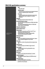
... thermistors selection for your entertainment goes wherever you go! - EPU, EPU switch ASUS Fan Xpert3 - Most advanced options with the most fun gaming platform under Windows® system ASUS EZ DIY Push Notice - Experience smooth online gaming with up to 32 Gb/s...for EZ BIOS download scheduling UEFI BIOS EZ Mode - UEFI BIOS - Perform each application with USB BIOS Flashback Wizard for M.2 - X99-E WS specifications summary ASUS Exclusive Features EPU - Turbo App - The ultra-fast transfer technology with lower pings and less lags Crystal Sound 2 - featuring friendly...
... thermistors selection for your entertainment goes wherever you go! - EPU, EPU switch ASUS Fan Xpert3 - Most advanced options with the most fun gaming platform under Windows® system ASUS EZ DIY Push Notice - Experience smooth online gaming with up to 32 Gb/s...for EZ BIOS download scheduling UEFI BIOS EZ Mode - UEFI BIOS - Perform each application with USB BIOS Flashback Wizard for M.2 - X99-E WS specifications summary ASUS Exclusive Features EPU - Turbo App - The ultra-fast transfer technology with lower pings and less lags Crystal Sound 2 - featuring friendly...

User Guide
Page 13
...x 8-pin EATX 12V Power connectors 1 x 6-pin EATX 12V_1 Power connector 1 x MemOK! ASUS EZ Flash 2 ASUS Exclusive Features Q-Design - ASUS Fanless Design: Heat-pipe solution 1 x BIOS Flashback button 1 x Q-Code Logger button 8...ASUS Q-DIMM - Tuner - ASUS Q-Shield - ASUS Q-LED (DIAG_CPU, DIAG_DRAM, DIAG_VGA, DIAG_ HDD) - ASUS Fan Xpert 3 - ASUS Q-Code - ASUS CrashFree BIOS 3 - button 1 x Clear CMOS button 1 x Chassis intrusion header 1 x DRCT (DirectKey) connector 1 x Dr. Power switch 1 x TPU switch (advanced two-stage adjustments) (continued on the next page) xiii ASUS O.C. X99-E WS...
...x 8-pin EATX 12V Power connectors 1 x 6-pin EATX 12V_1 Power connector 1 x MemOK! ASUS EZ Flash 2 ASUS Exclusive Features Q-Design - ASUS Fanless Design: Heat-pipe solution 1 x BIOS Flashback button 1 x Q-Code Logger button 8...ASUS Q-DIMM - Tuner - ASUS Q-Shield - ASUS Q-LED (DIAG_CPU, DIAG_DRAM, DIAG_VGA, DIAG_ HDD) - ASUS Fan Xpert 3 - ASUS Q-Code - ASUS CrashFree BIOS 3 - button 1 x Clear CMOS button 1 x Chassis intrusion header 1 x DRCT (DirectKey) connector 1 x Dr. Power switch 1 x TPU switch (advanced two-stage adjustments) (continued on the next page) xiii ASUS O.C. X99-E WS...

User Guide
Page 14
...X99-E WS specifications summary Internal I/O Connectors BIOS features Manageability Support DVD Operating system Form Factors 1 x EPU switch 1 x EZ XMP switch 1 x Power-on button 1 x Reset button 1 x 3-pin Chassis intrusion (CHASSIS) connector System Panel (Q-Connector) 128 Mb Flash ROM, UEFI AMI BIOS, PnP, DMI 2.7, WfM 2.0, SM BIOS 2.7, ACPI 5.0, Multi-language BIOS, ASUS... Control, F3 My Favorites, Quick Note, Last Modified Log, F12 PrintScreen function, F3 Shortcut function, and ASUS DRAM SPD (Serial Presence Detect) memory information WfM 2.0, DMI 2.7, WOL by PME, PXE Drivers Anti-virus...
...X99-E WS specifications summary Internal I/O Connectors BIOS features Manageability Support DVD Operating system Form Factors 1 x EPU switch 1 x EZ XMP switch 1 x Power-on button 1 x Reset button 1 x 3-pin Chassis intrusion (CHASSIS) connector System Panel (Q-Connector) 128 Mb Flash ROM, UEFI AMI BIOS, PnP, DMI 2.7, WfM 2.0, SM BIOS 2.7, ACPI 5.0, Multi-language BIOS, ASUS... Control, F3 My Favorites, Quick Note, Last Modified Log, F12 PrintScreen function, F3 Shortcut function, and ASUS DRAM SPD (Serial Presence Detect) memory information WfM 2.0, DMI 2.7, WOL by PME, PXE Drivers Anti-virus...

User Guide
Page 15
Package contents Check your motherboard package for the following items ASUS X99-E WS/USB 3.1 motherboard 12 x Serial ATA 6 Gb/s cables 1 x ASUS Q-Shield 1 x 3-WAY SLI bridge connector 1 x 2-in-1 ASUS Q-Connector kit COM port bracket 1 x 4-WAY SLI bridge connector 1 x ASUS SLI™ bridge connector User Manual Support DVD User Guide • If any of the above items is damaged or missing, contact your retailer. • The illustrated items above are for reference only. Actual product specifications may vary with different models. xv
Package contents Check your motherboard package for the following items ASUS X99-E WS/USB 3.1 motherboard 12 x Serial ATA 6 Gb/s cables 1 x ASUS Q-Shield 1 x 3-WAY SLI bridge connector 1 x 2-in-1 ASUS Q-Connector kit COM port bracket 1 x 4-WAY SLI bridge connector 1 x ASUS SLI™ bridge connector User Manual Support DVD User Guide • If any of the above items is damaged or missing, contact your retailer. • The illustrated items above are for reference only. Actual product specifications may vary with different models. xv

User Guide
Page 17
... six (6) USB 3.0 ports and ten (10) SATA 6 Gb/s ports. It also features backward compatibility with the speed of 3D graphics, multimedia and Internet applications. Chapter 1 ASUS X99-E WS/USB 3.1 1-1 Chapter 1: Product Introduction Product Introduction 1.1 Special features 1 1.1.1 Product highlights LGA2011-v3 socket for incredible visual clarity, detail, and realism. Intel®...
... six (6) USB 3.0 ports and ten (10) SATA 6 Gb/s ports. It also features backward compatibility with the speed of 3D graphics, multimedia and Internet applications. Chapter 1 ASUS X99-E WS/USB 3.1 1-1 Chapter 1: Product Introduction Product Introduction 1.1 Special features 1 1.1.1 Product highlights LGA2011-v3 socket for incredible visual clarity, detail, and realism. Intel®...

User Guide
Page 19
... or the power cord is detached from the wall socket before touching any motherboard settings. • Unplug the power cord from the power supply. Chapter 1 ASUS X99-E WS/USB 3.1 1-3 1.2 Motherboard overview 1.2.1 Before you proceed Take note of the following precautions before you install or remove any component, ensure that came with the component...
... or the power cord is detached from the wall socket before touching any motherboard settings. • Unplug the power cord from the power supply. Chapter 1 ASUS X99-E WS/USB 3.1 1-3 1.2 Motherboard overview 1.2.1 Before you proceed Take note of the following precautions before you install or remove any component, ensure that came with the component...

User Guide
Page 21
... 1-17 1-16 1-29 1-27 1-26 1-18 1-18 1-36 1-33 1-34 1-12 1-12 1-35 1-30 1-34 1-15 1-37 1-16 1-14 1-22 1-26 1-28 1-28 1-35 Chapter 1 ASUS X99-E WS/USB 3.1 1-5 USB 3.0 connectors (20-1 pin USB3_E78, USB3_E910) 9. CPU Over Voltage jumper (3-pin CPU_OV) 13. Digital audio connector (4-1 pin SPDIF_OUT) 29. Clear CMOS button (CLR_CMOS) 24...
... 1-17 1-16 1-29 1-27 1-26 1-18 1-18 1-36 1-33 1-34 1-12 1-12 1-35 1-30 1-34 1-15 1-37 1-16 1-14 1-22 1-26 1-28 1-28 1-35 Chapter 1 ASUS X99-E WS/USB 3.1 1-5 USB 3.0 connectors (20-1 pin USB3_E78, USB3_E910) 9. CPU Over Voltage jumper (3-pin CPU_OV) 13. Digital audio connector (4-1 pin SPDIF_OUT) 29. Clear CMOS button (CLR_CMOS) 24...

User Guide
Page 23
Recommended memory configurations Chapter 1 ASUS X99-E WS/USB 3.1 1-7 1.2.4 System memory The motherboard comes with eight DDR 4 (Double Data Rate 4) Quad Inline Memory Modules (DIMM) slots. A DDR4 module is notched differently from a DDR, DDR2, or DDR3 module. DO NOT install a DDR, DDR2, or DDR3 memory module to the DDR4 slot.
Recommended memory configurations Chapter 1 ASUS X99-E WS/USB 3.1 1-7 1.2.4 System memory The motherboard comes with eight DDR 4 (Double Data Rate 4) Quad Inline Memory Modules (DIMM) slots. A DDR4 module is notched differently from a DDR, DDR2, or DDR3 module. DO NOT install a DDR, DDR2, or DDR3 memory module to the DDR4 slot.

User Guide
Page 25
This slot automatically runs at x2 mode with ASUS Thunderbolt EX card installed. ASUS X99-E WS/USB 3.1 1-9 Failure to do so may cause you physical injury and damage motherboard components. 1.2.5 Expansion slots Unplug the power cord before adding or removing expansion ...
This slot automatically runs at x2 mode with ASUS Thunderbolt EX card installed. ASUS X99-E WS/USB 3.1 1-9 Failure to do so may cause you physical injury and damage motherboard components. 1.2.5 Expansion slots Unplug the power cord before adding or removing expansion ...

User Guide
Page 27
...; LAN2 (i210) ASMedia SATA Controller (106SE) ASMedia SATA Controller (1061) Intel® xHCI Intel® EHCI 1 Intel® EHCI 2 shared - - - shared - - - - - - shared - - - - - shared - - - shared - Chapter 1 ASUS X99-E WS/USB 3.1 1-11 PCIe x16_3 - Intel® LAN1 (i218LM) - - - - HD Audio - - - - - - shared - - - - - shared - - - - ASMedia Controller (1142) - - PCIe x16_5 shared - - - - - - SMBUS Controller - - shared - - - - - - Intel® SATA Controller...
...; LAN2 (i210) ASMedia SATA Controller (106SE) ASMedia SATA Controller (1061) Intel® xHCI Intel® EHCI 1 Intel® EHCI 2 shared - - - shared - - - - - - shared - - - - - shared - - - shared - Chapter 1 ASUS X99-E WS/USB 3.1 1-11 PCIe x16_3 - Intel® LAN1 (i218LM) - - - - HD Audio - - - - - - shared - - - - - shared - - - - ASMedia Controller (1142) - - PCIe x16_5 shared - - - - - - SMBUS Controller - - shared - - - - - - Intel® SATA Controller...

User Guide
Page 29
... BIOS overclocking, press the MemOK! A message will appear during the tuning process, the system continues memory tuning after turning on the computer. ASUS X99-E WS/USB 3.1 1-13 Chapter 1 Press and hold the MemOK! button to boot after using the MemOK! button lights continuously. Turn off the ...The blinking speed of the DIAG_DRAM LED. • The DIAG_DRAM LED also lights up due to the latest BIOS version from www.asus.com after the whole tuning process, the DIAG_DRAM LED lights continuously. function. MemOK! button Installing DIMMs that you turn off the system...
... BIOS overclocking, press the MemOK! A message will appear during the tuning process, the system continues memory tuning after turning on the computer. ASUS X99-E WS/USB 3.1 1-13 Chapter 1 Press and hold the MemOK! button to boot after using the MemOK! button lights continuously. Turn off the ...The blinking speed of the DIAG_DRAM LED. • The DIAG_DRAM LED also lights up due to the latest BIOS version from www.asus.com after the whole tuning process, the DIAG_DRAM LED lights continuously. function. MemOK! button Installing DIMMs that you turn off the system...

User Guide
Page 31
.... • You may change the EPU settings in the software application or BIOS setup program and enable the EPU function at the same time. Chapter 1 ASUS X99-E WS/USB 3.1 1-15 Enable this switch under Windows® OS environment, the EPU function will use the last setting you enable the EPU switch.
.... • You may change the EPU settings in the software application or BIOS setup program and enable the EPU function at the same time. Chapter 1 ASUS X99-E WS/USB 3.1 1-15 Enable this switch under Windows® OS environment, the EPU function will use the last setting you enable the EPU switch.

User Guide
Page 33
Chapter 1 ASUS X99-E WS/USB 3.1 1-17 EZ XMP switch Enable this switch to overclock the installed DIMMs, allowing you enable the EZ XMP switch. For the location of the EZ XMP LED, refer to enhance the DIMM's speed and performance. 8. The EZ XMP LED (XLED1) lights up when you to section 1.2.8 Onboard LEDs.
Chapter 1 ASUS X99-E WS/USB 3.1 1-17 EZ XMP switch Enable this switch to overclock the installed DIMMs, allowing you enable the EZ XMP switch. For the location of the EZ XMP LED, refer to enhance the DIMM's speed and performance. 8. The EZ XMP LED (XLED1) lights up when you to section 1.2.8 Onboard LEDs.

User Guide
Page 35
TPU LED (TPU_LED) The TPU LED lights up until the problem is enabled. Chapter 1 ASUS X99-E WS/USB 3.1 1-19 Diagnosis LEDs The Diagnosis LEDs provide the status of these key components during POST (PowerOn-Self Test): CPU, memory modules, VGA card, and hard disk drives. If an error is found, the critical component's LED stays lit up when the TPU switch is solved. 2. 1.2.8 Onboard LEDs 1.
TPU LED (TPU_LED) The TPU LED lights up until the problem is enabled. Chapter 1 ASUS X99-E WS/USB 3.1 1-19 Diagnosis LEDs The Diagnosis LEDs provide the status of these key components during POST (PowerOn-Self Test): CPU, memory modules, VGA card, and hard disk drives. If an error is found, the critical component's LED stays lit up when the TPU switch is solved. 2. 1.2.8 Onboard LEDs 1.

User Guide
Page 37
ASUS Dr. Power LED (PGLED3) This LED near the EATX PWR connector lights up when the Dr. Power switch is on and the power supply unit has failed. 5. PWR_SUPPLY LED The ASUS Dr. Power LED near the Dr. Power switch lights up when the ASUS Dr. Power switch setting is enabled. 6. Chapter 1 ASUS X99-E WS/USB 3.1 1-21
ASUS Dr. Power LED (PGLED3) This LED near the EATX PWR connector lights up when the Dr. Power switch is on and the power supply unit has failed. 5. PWR_SUPPLY LED The ASUS Dr. Power LED near the Dr. Power switch lights up when the ASUS Dr. Power switch setting is enabled. 6. Chapter 1 ASUS X99-E WS/USB 3.1 1-21