
User Guide
Page 1
Motherboard X99-A/USB 3.1
Motherboard X99-A/USB 3.1
User Guide
Page 3
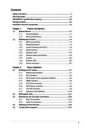
...X99-A/USB 3.1 specifications summary viii Package contents...xiv Installation tools and components xv Chapter 1: Product Introduction 1.1 Special features 1-1 1.1.1 Product highlights 1-1 1.1.2 Other special features 1-2 1.2 Motherboard overview 1-3 1.2.1 Before you proceed 1-3 1.2.2 Motherboard... 1.2.8 Onboard LEDs 1-25 1.2.9 Internal connectors 1-31 Chapter 2: Basic installation 2.1 Building your PC system 2-1 2.1.1 Motherboard installation 2-1 2.1.2 CPU installation 2-3 2.1.3 CPU heatsink and fan assembly installation 2-4 2.1.4 DIMM installation 2-6 2.1.5 ATX ...
...X99-A/USB 3.1 specifications summary viii Package contents...xiv Installation tools and components xv Chapter 1: Product Introduction 1.1 Special features 1-1 1.1.1 Product highlights 1-1 1.1.2 Other special features 1-2 1.2 Motherboard overview 1-3 1.2.1 Before you proceed 1-3 1.2.2 Motherboard... 1.2.8 Onboard LEDs 1-25 1.2.9 Internal connectors 1-31 Chapter 2: Basic installation 2.1 Building your PC system 2-1 2.1.1 Motherboard installation 2-1 2.1.2 CPU installation 2-3 2.1.3 CPU heatsink and fan assembly installation 2-4 2.1.4 DIMM installation 2-6 2.1.5 ATX ...

User Guide
Page 5
... read all the manuals that all cables are correctly connected and the power cables are connected. Operation safety • Before installing the motherboard and adding devices on a stable surface. • If you detect any damage, contact your retailer. If you are not sure about... the voltage of the electrical outlet you add a device. • Before connecting or removing signal cables from the motherboard, ensure that came with the product, contact a qualified service technician or your dealer immediately. • To avoid short circuits, keep paper clips...
... read all the manuals that all cables are correctly connected and the power cables are connected. Operation safety • Before installing the motherboard and adding devices on a stable surface. • If you detect any damage, contact your retailer. If you are not sure about... the voltage of the electrical outlet you add a device. • Before connecting or removing signal cables from the motherboard, ensure that came with the product, contact a qualified service technician or your dealer immediately. • To avoid short circuits, keep paper clips...

User Guide
Page 6
... 1: Product introduction This chapter describes the features of the BIOS parameters are not part of the switches, jumpers, and connectors on ASUS hardware and software products. 2. Detailed descriptions of the motherboard and the new technology it supports. These documents are also provided. About this guide is organized This guide contains the following...
... 1: Product introduction This chapter describes the features of the BIOS parameters are not part of the switches, jumpers, and connectors on ASUS hardware and software products. 2. Detailed descriptions of the motherboard and the new technology it supports. These documents are also provided. About this guide is organized This guide contains the following...
User Guide
Page 14
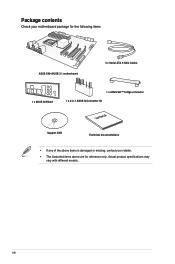
xiv Actual product specifications may vary with different models. Package contents Check your motherboard package for the following items ASUS X99-A/USB 3.1 motherboard 4 x Serial ATA 6 Gb/s cables 1 x ASUS Q-Shield 1 x ASUS SLI™ bridge connector 1 x 2-in-1 ASUS Q-Connector kit User Manual Support DVD Technical documentations • If any of the above items is damaged or missing, contact your retailer. • The illustrated items above are for reference only.
xiv Actual product specifications may vary with different models. Package contents Check your motherboard package for the following items ASUS X99-A/USB 3.1 motherboard 4 x Serial ATA 6 Gb/s cables 1 x ASUS Q-Shield 1 x ASUS SLI™ bridge connector 1 x 2-in-1 ASUS Q-Connector kit User Manual Support DVD Technical documentations • If any of the above items is damaged or missing, contact your retailer. • The illustrated items above are for reference only.

User Guide
Page 15
xv Installation tools and components Intel® LGA2011-v3 CPU Intel® LGA2011-v3 compatible CPU Fan PC chassis SATA hard disk drive Philips (cross) screwdriver Power supply unit 1 bag of screws DIMM SATA optical disc drive (optional) Graphics card The tools and components in the table above are not included in the motherboard package.
xv Installation tools and components Intel® LGA2011-v3 CPU Intel® LGA2011-v3 compatible CPU Fan PC chassis SATA hard disk drive Philips (cross) screwdriver Power supply unit 1 bag of screws DIMM SATA optical disc drive (optional) Graphics card The tools and components in the table above are not included in the motherboard package.
User Guide
Page 17
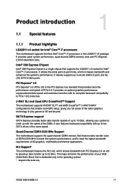
...and AMD CrossFire™ 2-WAY/3-WAY configurations that provides twice the performance and speed of the same speed. Chapter 1 ASUS X99-A/USB 3.1 1-1 Intel® X99 Express Chipset Intel® X99 Express Chipset is a single chipset that features data transfer rates of the SSDs. This helps enhance the performance of 3D...dedicated only to meet the higher bandwidth requirements of your system to 32 Gb/s. Quad-Channel DDR4 3333 MHz Support The motherboard supports the quad-channel DDR4 memory that supports the LGA2011-v3 socket for Intel® Core™ i7 processors This...
...and AMD CrossFire™ 2-WAY/3-WAY configurations that provides twice the performance and speed of the same speed. Chapter 1 ASUS X99-A/USB 3.1 1-1 Intel® X99 Express Chipset Intel® X99 Express Chipset is a single chipset that features data transfer rates of the SSDs. This helps enhance the performance of 3D...dedicated only to meet the higher bandwidth requirements of your system to 32 Gb/s. Quad-Channel DDR4 3333 MHz Support The motherboard supports the quad-channel DDR4 memory that supports the LGA2011-v3 socket for Intel® Core™ i7 processors This...

User Guide
Page 18
ErP Ready The motherboard is in line with ASUS vision of creating environment-friendly and energyefficient products through product design and innovation to energy consumptions. This is European Union's Energy-related ...reduce carbon footprint of the product and thus mitigate environmental impacts. Chapter 1 1-2 Chapter 1: Product introduction Complete USB 3.1 integration This motherboard has the latest USB 3.1 connectivity built in with dual Type-A ports for USB 3.1's breakneck speeds. 1.1.2 Other special features DTS Connect To get the most out of your audio entertainment across...
ErP Ready The motherboard is in line with ASUS vision of creating environment-friendly and energyefficient products through product design and innovation to energy consumptions. This is European Union's Energy-related ...reduce carbon footprint of the product and thus mitigate environmental impacts. Chapter 1 1-2 Chapter 1: Product introduction Complete USB 3.1 integration This motherboard has the latest USB 3.1 connectivity built in with dual Type-A ports for USB 3.1's breakneck speeds. 1.1.2 Other special features DTS Connect To get the most out of your audio entertainment across...
User Guide
Page 19
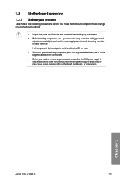
... the following precautions before you install or remove any component, ensure that came with the component. • Before you install motherboard components or change any motherboard settings. • Unplug the power cord from the wall socket before touching any component, place it on them. •...to the motherboard, peripherals, or components. Failure to do so may cause severe damage to avoid touching the ICs on a grounded antistatic pad or in the bag that the ATX power supply is switched off or the power cord is detached from the power supply. Chapter 1 ASUS X99-A/USB 3.1 1-3...
... the following precautions before you install or remove any component, ensure that came with the component. • Before you install motherboard components or change any motherboard settings. • Unplug the power cord from the wall socket before touching any component, place it on them. •...to the motherboard, peripherals, or components. Failure to do so may cause severe damage to avoid touching the ICs on a grounded antistatic pad or in the bag that the ATX power supply is switched off or the power cord is detached from the power supply. Chapter 1 ASUS X99-A/USB 3.1 1-3...

User Guide
Page 20
1.2.2 Motherboard layout Chapter 1 Refer to 1.2.9 Internal connectors and 2.3.1 Rear I/O connection for more information about rear panel connectors and internal connectors. 1-4 Chapter 1: Product introduction
1.2.2 Motherboard layout Chapter 1 Refer to 1.2.9 Internal connectors and 2.3.1 Rear I/O connection for more information about rear panel connectors and internal connectors. 1-4 Chapter 1: Product introduction

User Guide
Page 22
...PnP cap. ASUS will process Return Merchandise Authorization (RMA) requests only if the motherboard comes with a surface mount LGA2011-v3 socket designed for Intel® Core™ i7 processors. • Ensure that all power cables are not bent. 1.2.3 Central Processing Unit (CPU) The motherboard comes with ... misplacement/loss/incorrect removal of repair only if the damage is shipment/ transit-related. • Keep the cap after installing the motherboard. Contact your retailer immediately if the PnP cap is on the LGA2011-v3 socket. • The product warranty does not cover damage...
...PnP cap. ASUS will process Return Merchandise Authorization (RMA) requests only if the motherboard comes with a surface mount LGA2011-v3 socket designed for Intel® Core™ i7 processors. • Ensure that all power cables are not bent. 1.2.3 Central Processing Unit (CPU) The motherboard comes with ... misplacement/loss/incorrect removal of repair only if the damage is shipment/ transit-related. • Keep the cap after installing the motherboard. Contact your retailer immediately if the PnP cap is on the LGA2011-v3 socket. • The product warranty does not cover damage...
User Guide
Page 23
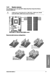
DO NOT install a DDR, DDR2, or DDR3 memory module to the DDR4 slot. 1.2.4 System memory The motherboard comes with eight DDR 4 (Double Data Rate 4) Quad Inline Memory Modules (DIMM) slots. Recommended memory configurations Chapter 1 ASUS X99-A/USB 3.1 1-7 A DDR4 module is notched differently from a DDR, DDR2, or DDR3 module.
DO NOT install a DDR, DDR2, or DDR3 memory module to the DDR4 slot. 1.2.4 System memory The motherboard comes with eight DDR 4 (Double Data Rate 4) Quad Inline Memory Modules (DIMM) slots. Recommended memory configurations Chapter 1 ASUS X99-A/USB 3.1 1-7 A DDR4 module is notched differently from a DDR, DDR2, or DDR3 module.

User Guide
Page 24
...DIMM sockets. • You may operate at a lower frequency than the vendor-marked value. For effective use a more memory on the motherboard. Under the default state, some memory modules for the OS can be about 3GB or less. Chapter 1 1-8 Chapter 1: Product introduction ...sized channel for single-channel operation. • According to the Microsoft® support site at http://support.microsoft. c) For more on the motherboard, the actual usable memory for overclocking may install varying memory sizes in Channel A, Channel B, Channel C, and Channel D. b) Install a 64-...
...DIMM sockets. • You may operate at a lower frequency than the vendor-marked value. For effective use a more memory on the motherboard. Under the default state, some memory modules for the OS can be about 3GB or less. Chapter 1 1-8 Chapter 1: Product introduction ...sized channel for single-channel operation. • According to the Microsoft® support site at http://support.microsoft. c) For more on the motherboard, the actual usable memory for overclocking may install varying memory sizes in Channel A, Channel B, Channel C, and Channel D. b) Install a 64-...
User Guide
Page 31
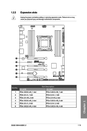
Failure to do so may cause you physical injury and damage motherboard components. Chapter 1 Slot No. 1 2 3 4 5 6 40-LANE PCIe 3.0/2.0 x16_1 slot PCIe 2.0 x1_1 slot PCIe 2.0 x16_2 slot PCIe 3.0/2.0 x16_3 slot PCIe 2.0 x1_2 slot PCIe 3.0/2.0 x16_4 slot Slot Description 28-LANE PCIe 3.0/2.0 x16_1 slot PCIe 2.0 x1_1 slot PCIe 2.0 x16_2 slot PCIe 3.0/2.0 x16_3 slot PCIe 2.0 x1_2 slot PCIe 3.0/2.0 x16_4 slot ASUS X99-A/USB 3.1 1-15 1.2.5 Expansion slots Unplug the power cord before adding or removing expansion cards.
Failure to do so may cause you physical injury and damage motherboard components. Chapter 1 Slot No. 1 2 3 4 5 6 40-LANE PCIe 3.0/2.0 x16_1 slot PCIe 2.0 x1_1 slot PCIe 2.0 x16_2 slot PCIe 3.0/2.0 x16_3 slot PCIe 2.0 x1_2 slot PCIe 3.0/2.0 x16_4 slot Slot Description 28-LANE PCIe 3.0/2.0 x16_1 slot PCIe 2.0 x1_1 slot PCIe 2.0 x16_2 slot PCIe 3.0/2.0 x16_3 slot PCIe 2.0 x1_2 slot PCIe 3.0/2.0 x16_4 slot ASUS X99-A/USB 3.1 1-15 1.2.5 Expansion slots Unplug the power cord before adding or removing expansion cards.

User Guide
Page 32
... will be disabled. • We recommend that you provide sufficient power when running CrossFireX™ or SLI™ mode. • Connect a chassis fan to the motherboard connector labeled CHA_FAN1-4 when using multiple graphics cards for better thermal environment. Chapter 1 1-16 Chapter 1: Product introduction
... will be disabled. • We recommend that you provide sufficient power when running CrossFireX™ or SLI™ mode. • Connect a chassis fan to the motherboard connector labeled CHA_FAN1-4 when using multiple graphics cards for better thermal environment. Chapter 1 1-16 Chapter 1: Product introduction
User Guide
Page 33
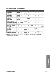
... shared - - - - - - - Intel® LAN1 (I218-V) - - - - shared - - Intel® EHCI 2 - - When the bandwidth is set to A. Chapter 1 ASUS X99-A/USB 3.1 1-17 shared - - - - - Intel® SATA Controller 1 - shared - - - HD Audio - - - - - - PCIe x16_3 shared - - - - - - - shared - - - - - Intel® xHCI - - - - - - - shared Intel® EHCI 1 - - - - - shared - shared - - - - ASMedia U3 Controller - - IRQ assignments for this motherboard A B C D E F G H PCIe x16_1 shared - - - - - - -
... shared - - - - - - - Intel® LAN1 (I218-V) - - - - shared - - Intel® EHCI 2 - - When the bandwidth is set to A. Chapter 1 ASUS X99-A/USB 3.1 1-17 shared - - - - - Intel® SATA Controller 1 - shared - - - HD Audio - - - - - - PCIe x16_3 shared - - - - - - - shared - - - - - Intel® xHCI - - - - - - - shared Intel® EHCI 1 - - - - - shared - shared - - - - ASMedia U3 Controller - - IRQ assignments for this motherboard A B C D E F G H PCIe x16_1 shared - - - - - - -

User Guide
Page 34
.... This is plugged to a power source indicating that allows you should shut down the system and unplug the power cable before removing or installing any motherboard component. 2. 1.2.6 Onboard buttons and switches Onboard buttons and switches allow you to fine-tune performance when working on button that you to power up or...
.... This is plugged to a power source indicating that allows you should shut down the system and unplug the power cable before removing or installing any motherboard component. 2. 1.2.6 Onboard buttons and switches Onboard buttons and switches allow you to fine-tune performance when working on button that you to power up or...
User Guide
Page 35
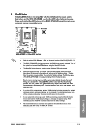
...tuning after using the MemOK! button lights continuously. If the test fails, the system reboots and test the next set of failsafe settings. ASUS X99-A/USB 3.1 1-19 Chapter 1 button Installing DIMMs that are not compatible with ones recommended in the Memory QVL (Qualified Vendors Lists) in this user... It takes about 5-10 seconds. • If your system fails to boot up when the DIMM is tested. Replace the DIMMs with the motherboard may cause system boot failure, and the DIAG_DRAM LED near the MemOK! function. MemOK! function. • The MemOK! button until the DIAG_DRAM...
...tuning after using the MemOK! button lights continuously. If the test fails, the system reboots and test the next set of failsafe settings. ASUS X99-A/USB 3.1 1-19 Chapter 1 button Installing DIMMs that are not compatible with ones recommended in the Memory QVL (Qualified Vendors Lists) in this user... It takes about 5-10 seconds. • If your system fails to boot up when the DIMM is tested. Replace the DIMMs with the motherboard may cause system boot failure, and the DIAG_DRAM LED near the MemOK! function. MemOK! function. • The MemOK! button until the DIAG_DRAM...

User Guide
Page 47
... using these connectors, set the SATA Mode item in the motherboard support DVD. • The SATAEXPRESS_1 connector can create a RAID 0, 1, 5, and 10 configuration with the Intel® Rapid Storage Technology through the onboard Intel® X99 chipset. Refer to section 3.6.3 PCH Storage Configuration for details.... and RAID configuration. If you can support one SATA Express device or two SATA devices. • Due to [AHCI Mode] by default. ASUS X99-A/USB 3.1 1-31 Chapter 1 • These connectors are set , refer to the manual bundled in the BIOS to Serial ATA 6 Gb/s hard...
... using these connectors, set the SATA Mode item in the motherboard support DVD. • The SATAEXPRESS_1 connector can create a RAID 0, 1, 5, and 10 configuration with the Intel® Rapid Storage Technology through the onboard Intel® X99 chipset. Refer to section 3.6.3 PCH Storage Configuration for details.... and RAID configuration. If you can support one SATA Express device or two SATA devices. • Due to [AHCI Mode] by default. ASUS X99-A/USB 3.1 1-31 Chapter 1 • These connectors are set , refer to the manual bundled in the BIOS to Serial ATA 6 Gb/s hard...

User Guide
Page 50
... USB 2.0 specification that supports up to the USB connector onboard if your chassis supports front panel USB ports. 5. USB 2.0 connectors (10-1 pin USB1112; You can connect the front panel USB cable to the ASUS Q-Connector (USB) first, and then install the Q-Connector (USB) to 48 Mb/s connection speed. The USB 2.0 module is purchased separately. Doing so will damage the motherboard...
... USB 2.0 specification that supports up to the USB connector onboard if your chassis supports front panel USB ports. 5. USB 2.0 connectors (10-1 pin USB1112; You can connect the front panel USB cable to the ASUS Q-Connector (USB) first, and then install the Q-Connector (USB) to 48 Mb/s connection speed. The USB 2.0 module is purchased separately. Doing so will damage the motherboard...


