Vintage-PE1 User''s Manual for English Edition
Page 8
... chapter helps you power up the system and install drivers and utilities from the support CD. 4 . Chapter 2: Basic installation This chapter provides step-by-step instructions on the front and rear panel, and internal components. 2. Chapter 4: Motherboard information This chapter gives information about the ASUS Vintage-PE1 barebone system. How this guide Audience This guide provides general information and installation instructions about the motherboard that comes with...
... chapter helps you power up the system and install drivers and utilities from the support CD. 4 . Chapter 2: Basic installation This chapter provides step-by-step instructions on the front and rear panel, and internal components. 2. Chapter 4: Motherboard information This chapter gives information about the ASUS Vintage-PE1 barebone system. How this guide Audience This guide provides general information and installation instructions about the motherboard that comes with...
Vintage-PE1 User''s Manual for English Edition
Page 10
A S U S V i n t a g e - Cable • AC power cable 3 . User guide x System package contents Check your Vintage-PE1 system package for the following items. If any of the items is damaged or missing, contact your retailer immediately. Item description 1 . Support CD 4 . P E 1 b a r e b o n e s y s t e m with • ASUS motherboard • 300 W power supply unit w/ PFC • ASUS chassis 2.
A S U S V i n t a g e - Cable • AC power cable 3 . User guide x System package contents Check your Vintage-PE1 system package for the following items. If any of the items is damaged or missing, contact your retailer immediately. Item description 1 . Support CD 4 . P E 1 b a r e b o n e s y s t e m with • ASUS motherboard • 300 W power supply unit w/ PFC • ASUS chassis 2.
Vintage-PE1 User''s Manual for English Edition
Page 17
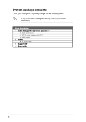
... your reference. Chassis fan 6. ASUS motherboard 7. DIMM sockets 8. AGP 8X slot 10. Floppy disk drive bay 3. LGA775 socket with PnP cap 9. Front panel cover 4. Power supply unit ASUS Vintage-PE1 1-7 PCI slots 11. Hard disk drive bay 5. 1.4 Internal components The illustration below is the internal view of the system when you remove the top cover and the power supply unit. The installed components are labeled for instructions on installing additional system components...
... your reference. Chassis fan 6. ASUS motherboard 7. DIMM sockets 8. AGP 8X slot 10. Floppy disk drive bay 3. LGA775 socket with PnP cap 9. Front panel cover 4. Power supply unit ASUS Vintage-PE1 1-7 PCI slots 11. Hard disk drive bay 5. 1.4 Internal components The illustration below is the internal view of the system when you remove the top cover and the power supply unit. The installed components are labeled for instructions on installing additional system components...
Vintage-PE1 User''s Manual for English Edition
Page 19
... came with it by adjusting the software settings. 1. Keep the screw for the card. 2. Turn on the next page. 3. Install the software drivers for information on the slot. 5. Remove the system unit cover (if your motherboard is completely seated on BIOS setup. 2. See Chapter 5 for the expansion card. ASUS Vintage-PE1 2-15 Secure the card to install expansion cards. 2.6 Expansion slots In the future, you...
... came with it by adjusting the software settings. 1. Keep the screw for the card. 2. Turn on the next page. 3. Install the software drivers for information on the slot. 5. Remove the system unit cover (if your motherboard is completely seated on BIOS setup. 2. See Chapter 5 for the expansion card. ASUS Vintage-PE1 2-15 Secure the card to install expansion cards. 2.6 Expansion slots In the future, you...

Vintage-PE1 User''s Manual for English Edition
Page 22
2.7 Installing an optical drive The optical drive is an optional item in this desktop system. Follow these steps to the instructions in this section if you acquired a model without an optical drive. Secure the optical drive with the holes on both sides of the bay. Place the chassis upright. 2. Insert the optical drive into the bay until its screw holes align with two screws on the bay as shown. 4. Refer to install an optical drive. 1. Screw holes Screws 2-18 Chapter 2: Basic installation Carefully push the optical drive into the upper 5.25-inch drive bay. 3.
2.7 Installing an optical drive The optical drive is an optional item in this desktop system. Follow these steps to the instructions in this section if you acquired a model without an optical drive. Secure the optical drive with the holes on both sides of the bay. Place the chassis upright. 2. Insert the optical drive into the bay until its screw holes align with two screws on the bay as shown. 4. Refer to install an optical drive. 1. Screw holes Screws 2-18 Chapter 2: Basic installation Carefully push the optical drive into the upper 5.25-inch drive bay. 3.

Vintage-PE1 User''s Manual for English Edition
Page 32
... and driver options may not be the same for other operating system versions. • The contents of your OS documentation for general reference only. Press the system power button ( ) to change at any time without notice. Refer to your hardware. 3.1 Installing an operating system The barebone system supports Windows® 2000/XP operating systems (OS). Because motherboard settings...
... and driver options may not be the same for other operating system versions. • The contents of your OS documentation for general reference only. Press the system power button ( ) to change at any time without notice. Refer to your hardware. 3.1 Installing an operating system The barebone system supports Windows® 2000/XP operating systems (OS). Because motherboard settings...

Vintage-PE1 User''s Manual for English Edition
Page 33
... Driver Installs the onboard SIS graphics driver. ASUS Vintage-PE1 3-3 When installed to install the Realtek® ALC655 audio driver and application. Realtek ALC655 Audio Driver Executes the wizard to the target system, this driver provides the method for configuring the chipset components. E X E to install If A u t o r u n is enabled in your optical drive. Realtek RTL8139 Ethernet Device Driver Installs the Realtek® RTL8139 Ethernet device driver. SIS AGP Driver Installs...
... Driver Installs the onboard SIS graphics driver. ASUS Vintage-PE1 3-3 When installed to install the Realtek® ALC655 audio driver and application. Realtek ALC655 Audio Driver Executes the wizard to the target system, this driver provides the method for configuring the chipset components. E X E to install If A u t o r u n is enabled in your optical drive. Realtek RTL8139 Ethernet Device Driver Installs the Realtek® RTL8139 Ethernet device driver. SIS AGP Driver Installs...

Vintage-PE1 User''s Manual for English Edition
Page 34
... up USB 2.0 Driver Installs the USB 2.0 driver. 3.3.2 Utilities menu The Utilities menu shows the applications and other software that the motherboard supports. ASUS Update The ASUS Update utility allows you keep your computer in a Windows® environment. ASUS PC Probe This smart utility monitors the fan speed, CPU temperature, and system voltages, and alerts you of any detected problems. This utility helps you to update the motherboard BIOS in...
... up USB 2.0 Driver Installs the USB 2.0 driver. 3.3.2 Utilities menu The Utilities menu shows the applications and other software that the motherboard supports. ASUS Update The ASUS Update utility allows you keep your computer in a Windows® environment. ASUS PC Probe This smart utility monitors the fan speed, CPU temperature, and system voltages, and alerts you of any detected problems. This utility helps you to update the motherboard BIOS in...

Vintage-PE1 User''s Manual for English Edition
Page 48
... on or puts the system in sleep mode. • Hard disk drive activity LED (Red 2-pin HDLED) This 2-pin connector is for the chassis-mounted reset button for easy connection. Pressing the power switch for more than four seconds while the system is ON turns...power. 4-12 Chapter 4: Motherboard info System panel connector (10-1 pin F_PANEL1) This connector supports several chassis-mounted functions. The LED lights up or flashes when data is read from the system chassis to the connector description below for details. • Power LED (Green 2-pin PLED) This 2-pin connector is color-coded...
... on or puts the system in sleep mode. • Hard disk drive activity LED (Red 2-pin HDLED) This 2-pin connector is for the chassis-mounted reset button for easy connection. Pressing the power switch for more than four seconds while the system is ON turns...power. 4-12 Chapter 4: Motherboard info System panel connector (10-1 pin F_PANEL1) This connector supports several chassis-mounted functions. The LED lights up or flashes when data is read from the system chassis to the connector description below for details. • Power LED (Green 2-pin PLED) This 2-pin connector is color-coded...

Vintage-PE1 User''s Manual for English Edition
Page 56
... after the utility completes the updating process. The ASUS Update utility allows you update the BIOS using this motherboard. The D r i v e r s menu appears. 2. X X. Place the support CD in the support CD that allows you to download the latest BIOS file. 5.1.5 ASUS Update utility The ASUS Update is available in the optical drive. Installing ASUS Update To install ASUS Update: 1. Doing so can cause system boot failure! 4. Quit all Windows® applications before you to...
... after the utility completes the updating process. The ASUS Update utility allows you update the BIOS using this motherboard. The D r i v e r s menu appears. 2. X X. Place the support CD in the support CD that allows you to download the latest BIOS file. 5.1.5 ASUS Update utility The ASUS Update is available in the optical drive. Installing ASUS Update To install ASUS Update: 1. Doing so can cause system boot failure! 4. Quit all Windows® applications before you to...

Vintage-PE1 User''s Manual for English Edition
Page 81
... error occurs. Security Settings Supervisor Password : Not Installed User Password : Not Installed Change Supervisor Password Change User Password Clear User Password to trap Interrupt 19. Change Supervisor Password Select this function allows the option ROMs to change the supervisor password. Confirm the password when prompted. ASUS Vintage-PE1 5-31 Configuration options: [Disabled] [Enabled] 5.6.5 Security The Security menu items allow you to enable or disable support for the F1 key to set...
... error occurs. Security Settings Supervisor Password : Not Installed User Password : Not Installed Change Supervisor Password Change User Password Clear User Password to trap Interrupt 19. Change Supervisor Password Select this function allows the option ROMs to change the supervisor password. Confirm the password when prompted. ASUS Vintage-PE1 5-31 Configuration options: [Disabled] [Enabled] 5.6.5 Security The Security menu items allow you to enable or disable support for the F1 key to set...

Vintage-PE1 User''s Manual for English Edition
Page 82
... to set a password, this item to selected fields, such as in the Setup utility. Change User Password Select this item shows I n s t a l l e d. After you set or change the user password. See section "4.3 Jumpers" for information on top of the screen shows the default N o t I n s t a l l e d. 5-32 Chapter 5: BIOS setup After you have set your BIOS password, you to select the access restriction to the Setup items. Configuration options...
... to set a password, this item to selected fields, such as in the Setup utility. Change User Password Select this item shows I n s t a l l e d. After you set or change the user password. See section "4.3 Jumpers" for information on top of the screen shows the default N o t I n s t a l l e d. 5-32 Chapter 5: BIOS setup After you have set your BIOS password, you to select the access restriction to the Setup items. Configuration options...

Vintage-PE1 User''s Manual for English E2012
Page 10
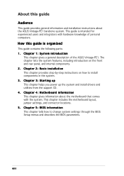
P E 1 b a r e b o n e s y s t e m with • ASUS motherboard • 300 W power supply unit w/ PFC • ASUS chassis 2. A S U S V i n t a g e - User guide x System package contents Check your Vintage-PE1 system package for the following items. If any of the items is damaged or missing, contact your retailer immediately. Support CD 4 . Cable • AC power cable 3 . Item description 1 .
P E 1 b a r e b o n e s y s t e m with • ASUS motherboard • 300 W power supply unit w/ PFC • ASUS chassis 2. A S U S V i n t a g e - User guide x System package contents Check your Vintage-PE1 system package for the following items. If any of the items is damaged or missing, contact your retailer immediately. Support CD 4 . Cable • AC power cable 3 . Item description 1 .

Vintage-PE1 User''s Manual for English E2012
Page 19
... and change the necessary BIOS settings, if any. Keep the screw for the card. 2. Before installing the expansion card, read the documentation that came with the screw you physical injury and damage motherboard components. 2.6.1 Installing an expansion card To install an expansion card: 1. Turn on the slot. 5. ASUS Vintage-PE1 2-15 Replace the system cover. 2.6.2 Configuring an expansion card After installing the expansion card, configure the it and make...
... and change the necessary BIOS settings, if any. Keep the screw for the card. 2. Before installing the expansion card, read the documentation that came with the screw you physical injury and damage motherboard components. 2.6.1 Installing an expansion card To install an expansion card: 1. Turn on the slot. 5. ASUS Vintage-PE1 2-15 Replace the system cover. 2.6.2 Configuring an expansion card After installing the expansion card, configure the it and make...

Vintage-PE1 User''s Manual for English E2012
Page 22
Secure the optical drive with the holes on both sides of the bay. 2.7 Installing an optical drive The optical drive is an optional item in this desktop system. Carefully push the optical drive into the upper 5.25-inch drive bay. 3. Screw holes Screws 2-18 Chapter 2: Basic installation Insert the optical drive into the bay until its screw holes align with two screws on the bay as shown. 4. Follow these steps to the instructions in this section if you acquired a model without an optical drive. Refer to install an optical drive. 1. Place the chassis upright. 2.
Secure the optical drive with the holes on both sides of the bay. 2.7 Installing an optical drive The optical drive is an optional item in this desktop system. Carefully push the optical drive into the upper 5.25-inch drive bay. 3. Screw holes Screws 2-18 Chapter 2: Basic installation Insert the optical drive into the bay until its screw holes align with two screws on the bay as shown. 4. Follow these steps to the instructions in this section if you acquired a model without an optical drive. Refer to install an optical drive. 1. Place the chassis upright. 2.

Vintage-PE1 User''s Manual for English E2012
Page 32
... display and driver options may not be the same for more information. 3.2 Powering up Visit the ASUS website for general reference only. Always install the latest OS version and corresponding updates so you can maximize the features of the support CD are subject to enter the OS. Because motherboard settings and hardware options vary, use the setup procedures presented...
... display and driver options may not be the same for more information. 3.2 Powering up Visit the ASUS website for general reference only. Always install the latest OS version and corresponding updates so you can maximize the features of the support CD are subject to enter the OS. Because motherboard settings and hardware options vary, use the setup procedures presented...

Vintage-PE1 User''s Manual for English E2012
Page 48
...on the BIOS settings. Connect the HDD Activity LED cable to this connector. Pressing the power switch for more than four seconds while the system is ON turns the system OFF. • Reset button (Blue 2-pin RESET) This 2-pin connector is color-coded for the Power LED. The IDE LED lights up ...when you turn on or puts the system in sleep mode. • Hard disk drive activity LED (Red 2-pin HDLED) This 2-pin connector is for the HDD Activity LED. Refer to the HDD. • ATX power button/soft-off button ...
...on the BIOS settings. Connect the HDD Activity LED cable to this connector. Pressing the power switch for more than four seconds while the system is ON turns the system OFF. • Reset button (Blue 2-pin RESET) This 2-pin connector is color-coded for the Power LED. The IDE LED lights up ...when you turn on or puts the system in sleep mode. • Hard disk drive activity LED (Red 2-pin HDLED) This 2-pin connector is for the HDD Activity LED. Refer to the HDD. • ATX power button/soft-off button ...

Vintage-PE1 User''s Manual for English E2012
Page 56
... the ASUS website (www.asus.com) to manage, save, and update the motherboard BIOS in Windows® environment. Restart the system after the utility completes the updating process. Quit all Windows® applications before you to your system. Installing ASUS Update To install ASUS Update: 1. See page 3-4 for this utility. 5-8 Chapter 5: BIOS setup Click the U t i l i t i e s tab, then click I n s t a l l A S U S U p d a t e V X . The recovered BIOS may not be the latest BIOS version...
... the ASUS website (www.asus.com) to manage, save, and update the motherboard BIOS in Windows® environment. Restart the system after the utility completes the updating process. Quit all Windows® applications before you to your system. Installing ASUS Update To install ASUS Update: 1. See page 3-4 for this utility. 5-8 Chapter 5: BIOS setup Click the U t i l i t i e s tab, then click I n s t a l l A S U S U p d a t e V X . The recovered BIOS may not be the latest BIOS version...

Vintage-PE1 User''s Manual for English E2012
Page 81
... to be pressed when error occurs. Configuration options: [Disabled] [Enabled] Interrupt 19 Capture [Disabled] When set to [Enabled], this item to set to Enabled, the system displays the message "Press DEL to run Setup" during POST. Security Settings Supervisor Password : Not Installed User Password : Not Installed Change Supervisor Password Change User Password Clear User Password to change the system security settings. ASUS Vintage-PE1 5-31 Change Supervisor Password Select this function...
... to be pressed when error occurs. Configuration options: [Disabled] [Enabled] Interrupt 19 Capture [Disabled] When set to [Enabled], this item to set to Enabled, the system displays the message "Press DEL to run Setup" during POST. Security Settings Supervisor Password : Not Installed User Password : Not Installed Change Supervisor Password Change User Password Clear User Password to change the system security settings. ASUS Vintage-PE1 5-31 Change Supervisor Password Select this function...

Vintage-PE1 User''s Manual for English E2012
Page 82
... setting a user password. After you have set your BIOS password, you to change other items appear to allow change the supervisor password, follow the same steps as Date and Time. Security Settings Supervisor Password : Not Installed User Password : Not Installed Change Supervisor Password User Access Level Change User Password Clear User Password Password Check [Full Access] [Setup] User Access Level (Full Access] This item allows you successfully set a supervisor password, the other security settings. Change User Password...
... setting a user password. After you have set your BIOS password, you to change other items appear to allow change the supervisor password, follow the same steps as Date and Time. Security Settings Supervisor Password : Not Installed User Password : Not Installed Change Supervisor Password User Access Level Change User Password Clear User Password Password Check [Full Access] [Setup] User Access Level (Full Access] This item allows you successfully set a supervisor password, the other security settings. Change User Password...


