VINTAGE-PE1 Motherboard - Asus
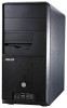
VINTAGE-PE1 Motherboard
Related Manual Pages


Related Terms
The following terms were also used when searching for VINTAGE-PE1 Motherboard - Asus:- vintage pe1 driver
- vintage pe1 problems
- vintage pe1 power supply
- vintage pe1 parts
- vintage pe1 motherboard
- vintage pe1 memory
- vintage pe1 manual
- vintage pe1 fan
- vintage pe1 drivers
- vintage pe1 specifications
- vintage pe1 cpu
- vintage pe1 bios
- vintage pe1 barebones
- vintage pe1 barebone system
- vintage pe1 barebone
- vintage pe1 audio driver
- vintage pe1 asus
- vintage-pe1 cpu support
- vintage-pe1 specifications
- vintage-pe1 ram
- vintage-pe1 power supply
- vintage-pe1 motherboard
- vintage-pe1 memory upgrade
- vintage-pe1 memory
- vintage-pe1 manual
- vintage-pe1 drivers
- vintage pe1
- vintage-pe1 bios update
- vintage-pe1 bios
- vintage-pe1 barebone
- vintage-pe1
- vintage pe1 video card
- vintage pe1 system
- vintage pe1 support
- asus vintage pe1 driver
- asus vintage pe1 specifications
- asus vintage pe1 problems
- asus vintage pe1 power supply
- asus vintage pe1 parts
- asus vintage pe1 motherboard
- asus vintage pe1 memory
- asus vintage pe1 manual
- asus vintage pe1 drivers
- asus vintage pe1 support
- asus vintage pe1 cpu
- asus vintage pe1 bios
- asus vintage pe1 barebones
- asus vintage pe1 barebone system
- asus vintage pe1 barebone
- asus vintage pe1
- asus pc vintage pe1
- asus vintage-pe1 memory upgrade
- pc vintage pe1
- driver asus vintage-pe1
- barebone vintage pe1
- asustek vintage-pe1
- asus vintage-pe1 specifications
- asus vintage-pe1 ram
- asus vintage-pe1 power supply
- asus vintage-pe1 motherboard
- asus barebone vintage pe1
- asus vintage-pe1 memory
- asus vintage-pe1 drivers
- asus vintage-pe1 bios
- asus vintage-pe1 barebone
- asus vintage-pe1
- asus vintage pe1 video card
- asus vintage pe1 system