
TUSL2 User Manual
Page 1
® TUSL2 Intel® 815E ATX Motherboard USER'S MANUAL
® TUSL2 Intel® 815E ATX Motherboard USER'S MANUAL

TUSL2 User Manual
Page 4
... 58 4.4 Advanced Menu 60 4.4.1 4.4.2 4.4.3 4.4.4 Chip Configuration 63 I/O Device Configuration 66 PCI Configuration 68 Shadow Configuration 70 4 ASUS TUSL2 User's Manual FEATURES 8 2.1 The ASUS TUSL2 8 2.2 TUSL2 Motherboard Components 12 3. HARDWARE SETUP 14 3.1 TUSL2 Motherboard Layout 14 3.2 Layout Contents 15 3.3 Hardware Setup Procedure 17 3.4 Motherboard Settings 17 3.5 System Memory (DIMM 25 3.5.1 General DIMM Notes 25 3.5.2 Memory Installation 26 3.6 Central Processing Unit...
... 58 4.4 Advanced Menu 60 4.4.1 4.4.2 4.4.3 4.4.4 Chip Configuration 63 I/O Device Configuration 66 PCI Configuration 68 Shadow Configuration 70 4 ASUS TUSL2 User's Manual FEATURES 8 2.1 The ASUS TUSL2 8 2.2 TUSL2 Motherboard Components 12 3. HARDWARE SETUP 14 3.1 TUSL2 Motherboard Layout 14 3.2 Layout Contents 15 3.3 Hardware Setup Procedure 17 3.4 Motherboard Settings 17 3.5 System Memory (DIMM 25 3.5.1 General DIMM Notes 25 3.5.2 Memory Installation 26 3.6 Central Processing Unit...

TUSL2 User Manual
Page 5
... 4.7 Exit Menu 78 5. SOFTWARE SETUP 93 6.1 Winbond Smart Manager 93 6.2 ASUS PC Probe 97 6.3 Multi-Channel Audio Feature Setup 102 6.4 ASUS LiveUpdate 104 6.5 CyberLink PowerPlayer SE 105 6.6 CyberLink VideoLive Mail 106 7. SOFTWARE SETUP 81 5.1 Install Operating System 81 5.2 Start Windows 81 5.3 TUSL2 Motherboard Support CD 82 5.3.1 Installation Menu 82 5.4 Using the Promise Chip for...
... 4.7 Exit Menu 78 5. SOFTWARE SETUP 93 6.1 Winbond Smart Manager 93 6.2 ASUS PC Probe 97 6.3 Multi-Channel Audio Feature Setup 102 6.4 ASUS LiveUpdate 104 6.5 CyberLink PowerPlayer SE 105 6.6 CyberLink VideoLive Mail 106 7. SOFTWARE SETUP 81 5.1 Install Operating System 81 5.2 Start Windows 81 5.3 TUSL2 Motherboard Support CD 82 5.3.1 Installation Menu 82 5.4 Using the Promise Chip for...
TUSL2 User Manual
Page 7
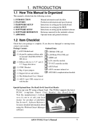
...The Read2-In-01 SmartCard Reader Power up your package is divided into the following sections: 1. ASUS TUSL2 User's Manual 7 1. SOFTWARE SETUP 6. Package Contents Optional Items (1) ASUS Motherboard (2) 40-pin 80-conductor ribbon cable for internal UltraDMA100/66/33 IDE drives (1) Ribbon cable ...com.tw or ask your retailer. APPENDIX Manual information and checklist Production information and specifications Intructions on setting up the motherboard. The TUSL2 supports the latest PC/SC compliant Smart Card Reader: the Read2-In-01. INTRODUCTION 2. See Section 6, Software ...
...The Read2-In-01 SmartCard Reader Power up your package is divided into the following sections: 1. ASUS TUSL2 User's Manual 7 1. SOFTWARE SETUP 6. Package Contents Optional Items (1) ASUS Motherboard (2) 40-pin 80-conductor ribbon cable for internal UltraDMA100/66/33 IDE drives (1) Ribbon cable ...com.tw or ask your retailer. APPENDIX Manual information and checklist Production information and specifications Intructions on setting up the motherboard. The TUSL2 supports the latest PC/SC compliant Smart Card Reader: the Read2-In-01. INTRODUCTION 2. See Section 6, Software ...
TUSL2 User Manual
Page 8
... Wake-On-Ring, Keyboard Wake-Up, and BIOS Wake-Up. • Smart Card Reader Compatible: PC/SC compliant Smart Card Reader connectivity. 8 ASUS TUSL2 User's Manual FEATURES 2.1 The ASUS TUSL2 The ASUS TUSL2 motherboard is carefully designed for up to PIII® Coppermine™ and Celeron™ CPUs. two USB controllers for a total of 4 USB ports. •...
... Wake-On-Ring, Keyboard Wake-Up, and BIOS Wake-Up. • Smart Card Reader Compatible: PC/SC compliant Smart Card Reader connectivity. 8 ASUS TUSL2 User's Manual FEATURES 2.1 The ASUS TUSL2 The ASUS TUSL2 motherboard is carefully designed for up to PIII® Coppermine™ and Celeron™ CPUs. two USB controllers for a total of 4 USB ports. •...

TUSL2 User Manual
Page 9
...power before plugging and unplugging devices so as xDSL. • PCI Expansion Slots: Provides six 32-bit PCI (PCI 2.2 compliant) expansion slots. ASUS TUSL2 User's Manual 9 FEATURES Specifications 2. UART2 can support Bus Master PCI cards, such as SCSI or LAN cards. (PCI supports up when there...be directed from PCI master busses to the memory and processor. • Onboard LED: The onboard LED will light up to the motherboard. JumperFree also permits Vcore voltage adjustments through the BIOS. 2. Alternatively, easy-to-use DIP switches instead of jumpers are supplied onboard ...
...power before plugging and unplugging devices so as xDSL. • PCI Expansion Slots: Provides six 32-bit PCI (PCI 2.2 compliant) expansion slots. ASUS TUSL2 User's Manual 9 FEATURES Specifications 2. UART2 can support Bus Master PCI cards, such as SCSI or LAN cards. (PCI supports up when there...be directed from PCI master busses to the memory and processor. • Onboard LED: The onboard LED will light up to the motherboard. JumperFree also permits Vcore voltage adjustments through the BIOS. 2. Alternatively, easy-to-use DIP switches instead of jumpers are supplied onboard ...

TUSL2 User Manual
Page 10
...Concurrent PCI: Concurrent PCI allows multiple PCI transfers from PCI master buses to memory and processor. • SDRAM Optimized Performance: This motherboard supports PC133-compliant Synchronous Dynamic Random Access Memory (SDRAM), which increases the data transfer rate to 1066MB/s max. • ACPI ...ACPI provides more Energy Saving Features for Windows 95/98/ NT. Color-coded connectors and descriptive icons make identification easy. 10 ASUS TUSL2 User's Manual With these features implemented in two channels. Data "mirroring," or RAID 1, improves system fault tolerance as the ...
...Concurrent PCI: Concurrent PCI allows multiple PCI transfers from PCI master buses to memory and processor. • SDRAM Optimized Performance: This motherboard supports PC133-compliant Synchronous Dynamic Random Access Memory (SDRAM), which increases the data transfer rate to 1066MB/s max. • ACPI ...ACPI provides more Energy Saving Features for Windows 95/98/ NT. Color-coded connectors and descriptive icons make identification easy. 10 ASUS TUSL2 User's Manual With these features implemented in two channels. Data "mirroring," or RAID 1, improves system fault tolerance as the ...
TUSL2 User Manual
Page 11
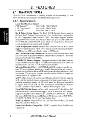
...8226; Temperature Monitoring andAlert: To prevent system overheat and system damage, this benefit on remotely through BIOS setup to allow the computer to critical motherboard components. All the fans are monitored to ensure stable current to be enabled or disabled through an internal or external modem. With this..., users can access any information from a fax/modem. A simple glimpse provides useful information to prevent possible application crashes. FEATURES Intelligence 2. The onboard hardware ASUS ASIC in 3.8 Connectors for RPM and failure. ASUS TUSL2 User's Manual 11
...8226; Temperature Monitoring andAlert: To prevent system overheat and system damage, this benefit on remotely through BIOS setup to allow the computer to critical motherboard components. All the fans are monitored to ensure stable current to be enabled or disabled through an internal or external modem. With this..., users can access any information from a fax/modem. A simple glimpse provides useful information to prevent possible application crashes. FEATURES Intelligence 2. The onboard hardware ASUS ASIC in 3.8 Connectors for RPM and failure. ASUS TUSL2 User's Manual 11
TUSL2 User Manual
Page 12
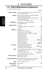
...Connectors (ATA100 Support 5 2 IDE Connectors (ATA100 / RAID 0 or 1 Support 7 1 Smart Card Connector 12 1 Serial COM2 Header 18 1 ASUS iPanel Connector 10 1 Parallel Port Connector 28 1 Serial COM1 Port Connector Bottom) 29 2 USB Port Connectors 30 1 PS/2 Mouse Connector Top) 31...Monitoring System Voltage Monitoring (integrated in ASUS ASIC) ....... 17 3 Fan Power and Speed Monitoring Connectors Power ATX Power Supply Connector 1 Special Feature Onboard LED 20 Form Factor ATX 12 ASUS TUSL2 User's Manual FEATURES 2.2 TUSL2 Motherboard Components See opposite page for locations. ...
...Connectors (ATA100 Support 5 2 IDE Connectors (ATA100 / RAID 0 or 1 Support 7 1 Smart Card Connector 12 1 Serial COM2 Header 18 1 ASUS iPanel Connector 10 1 Parallel Port Connector 28 1 Serial COM1 Port Connector Bottom) 29 2 USB Port Connectors 30 1 PS/2 Mouse Connector Top) 31...Monitoring System Voltage Monitoring (integrated in ASUS ASIC) ....... 17 3 Fan Power and Speed Monitoring Connectors Power ATX Power Supply Connector 1 Special Feature Onboard LED 20 Form Factor ATX 12 ASUS TUSL2 User's Manual FEATURES 2.2 TUSL2 Motherboard Components See opposite page for locations. ...

TUSL2 User Manual
Page 14
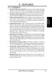
HARDWARE SETUP 3.1 TUSL2 Motherboard Layout PS/2KBMS T: Mouse B: Keyboard USB T: Port1 B: ...AUX CD AAPANEL MODEM HPHONE BCS1 BCS2 CMI8738 Audio Controller JTPWR PCI1 PCI2 WOL_CON PCI3 PLED2 PCI4 PCI5 TUSL2 PCI6 OC3 CNR_SLOT COM2 CR2032 3V Lithium Cell CMOS Power Intel I/O Controller Hub (ICH2) CLRTC &#...Controller Firmware Hub (FWH) ASUS ASIC with Hardware Monitor JP3 JEN JP4 ACHA WOR Super I/O CHA_FAN USBPWR23 USB23 AFPANEL IDELED SMARTCARD PANEL Grayed components are optional at the time of purchase. 14 ASUS TUSL2 User's Manual 3. H/W SETUP Motherboard Layout 3.
HARDWARE SETUP 3.1 TUSL2 Motherboard Layout PS/2KBMS T: Mouse B: Keyboard USB T: Port1 B: ...AUX CD AAPANEL MODEM HPHONE BCS1 BCS2 CMI8738 Audio Controller JTPWR PCI1 PCI2 WOL_CON PCI3 PLED2 PCI4 PCI5 TUSL2 PCI6 OC3 CNR_SLOT COM2 CR2032 3V Lithium Cell CMOS Power Intel I/O Controller Hub (ICH2) CLRTC &#...Controller Firmware Hub (FWH) ASUS ASIC with Hardware Monitor JP3 JEN JP4 ACHA WOR Super I/O CHA_FAN USBPWR23 USB23 AFPANEL IDELED SMARTCARD PANEL Grayed components are optional at the time of purchase. 14 ASUS TUSL2 User's Manual 3. H/W SETUP Motherboard Layout 3.

TUSL2 User Manual
Page 15
H/W SETUP Layout Contents 3. 3. HARDWARE SETUP 3.2 Layout Contents Motherboard Settings 1) JEN 2) JP3 3) JP4 4) USBPWR01 USBPWR23 5) OC3 6) KBPWR 7) DSW 8) VIO 9) BCS p.18 JumperFree™ Mode (Enable/Disable) p.19 ATA100 / RAID 0/1 (Enable) p.19 Onboard IDE (Enable/... Connectors (Four 4-pins) (optional) 14) EARPHONE p.38 Headphone True-Level Line Out Header (3 pins) 15) MIC2 p.39 Internal Microphone Connector (3 pins) 16) AFPANEL/IR_CON p.39 ASUS iPanel Connector (12-1 pins) 17) AAPANEL p.40 ASUS iPanel Audio Connector (12-1 pins) ASUS TUSL2 User's Manual 15
H/W SETUP Layout Contents 3. 3. HARDWARE SETUP 3.2 Layout Contents Motherboard Settings 1) JEN 2) JP3 3) JP4 4) USBPWR01 USBPWR23 5) OC3 6) KBPWR 7) DSW 8) VIO 9) BCS p.18 JumperFree™ Mode (Enable/Disable) p.19 ATA100 / RAID 0/1 (Enable) p.19 Onboard IDE (Enable/... Connectors (Four 4-pins) (optional) 14) EARPHONE p.38 Headphone True-Level Line Out Header (3 pins) 15) MIC2 p.39 Internal Microphone Connector (3 pins) 16) AFPANEL/IR_CON p.39 ASUS iPanel Connector (12-1 pins) 17) AAPANEL p.40 ASUS iPanel Audio Connector (12-1 pins) ASUS TUSL2 User's Manual 15
TUSL2 User Manual
Page 17
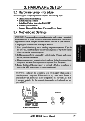
.... Place components on a grounded antistatic pad or on the bag that you must complete the following steps: • Check Motherboard Settings • Install Memory Modules • Install the Central Processing Unit (CPU) • Install Expansion Cards • ...Setup Procedure Before using your computer, you unplug your computer when working on the motherboard. 3. Computer motherboards and expansion cards contain very delicate Integrated Circuit (IC) chips. WARNING! COM1 PLED2 ® TUSL2 TUSL2 Onboard LED ON Standby Power OFF Powered Off ASUS TUSL2 User's Manual 17
.... Place components on a grounded antistatic pad or on the bag that you must complete the following steps: • Check Motherboard Settings • Install Memory Modules • Install the Central Processing Unit (CPU) • Install Expansion Cards • ...Setup Procedure Before using your computer, you unplug your computer when working on the motherboard. 3. Computer motherboards and expansion cards contain very delicate Integrated Circuit (IC) chips. WARNING! COM1 PLED2 ® TUSL2 TUSL2 Onboard LED ON Standby Power OFF Powered Off ASUS TUSL2 User's Manual 17

TUSL2 User Manual
Page 18
...Frequency Selection 3. NOTE: In JumperFree™ mode, all the switches in the OFF position. HARDWARE SETUP Motherboard Feature Settings The motherboard's onboard functions are either adjusted through the BIOS setup (see 4.4 Advanced Menu). Frequency Selection. 3. ...TUSL2 TUSL2 DIP Switches ON OFF 1. Frequency Selection 5. Frequency Selection 4. Setting JEN Disable (Jumper) [1-2] Enable (JumperFree) [2-3] (default) DSW COM1 ON 12345 JEN 12 ® TUSL2 Disable Jumper Mode TUSL2 JumperFree™ Mode Setting OFF JEN 23 Enable JumperFree Mode (Default) 18 ASUS TUSL2...
...Frequency Selection 3. NOTE: In JumperFree™ mode, all the switches in the OFF position. HARDWARE SETUP Motherboard Feature Settings The motherboard's onboard functions are either adjusted through the BIOS setup (see 4.4 Advanced Menu). Frequency Selection. 3. ...TUSL2 TUSL2 DIP Switches ON OFF 1. Frequency Selection 5. Frequency Selection 4. Setting JEN Disable (Jumper) [1-2] Enable (JumperFree) [2-3] (default) DSW COM1 ON 12345 JEN 12 ® TUSL2 Disable Jumper Mode TUSL2 JumperFree™ Mode Setting OFF JEN 23 Enable JumperFree Mode (Default) 18 ASUS TUSL2...

TUSL2 User Manual
Page 19
.... Setting JP4 Enable Onboard IDE [1-2] (default) Disable Onboard IDE [3-4] COM1 ® TUSL2 TUSL2 Onboard IDE Selection JP4 12 23 ENABLE Onboard IDE DISABLE Onboard IDE (Default) ASUS TUSL2 User's Manual 19 HARDWARE SETUP 2) ATA100 / RAID 0/1 (JP3) These jumpers enable ...Enable ATA100 [2-3] (default) Enable RAID 0/1 [1-2] COM1 ® TUSL2 TUSL2 ATA100/RAIDO Selection JP3 12 23 RAID0/1 ATA100 (Default) 3) Onboard IDE ( JP4) These jumpers enable or disable the IDE function of the motherboard. H/W SETUP Motherboard Settings 3. The default setting is ATA100.
.... Setting JP4 Enable Onboard IDE [1-2] (default) Disable Onboard IDE [3-4] COM1 ® TUSL2 TUSL2 Onboard IDE Selection JP4 12 23 ENABLE Onboard IDE DISABLE Onboard IDE (Default) ASUS TUSL2 User's Manual 19 HARDWARE SETUP 2) ATA100 / RAID 0/1 (JP3) These jumpers enable ...Enable ATA100 [2-3] (default) Enable RAID 0/1 [1-2] COM1 ® TUSL2 TUSL2 ATA100/RAIDO Selection JP3 12 23 RAID0/1 ATA100 (Default) 3) Onboard IDE ( JP4) These jumpers enable or disable the IDE function of the motherboard. H/W SETUP Motherboard Settings 3. The default setting is ATA100.

TUSL2 User Manual
Page 22
....2MHz 100.3MHz 103.0MHz 100.30MHz AGP 66.8MHz 66.8MHz 68.7MHz 66.85MHz ® ON 12345 ON 12345 ON 12345 ON 12345 TUSL2 TUSL2 CPU External CPU DRAM Clock (BUS) Frequency AGP Selection 140MHz 133.70MHz 105MHz 133.70MHz 70MHz 66.85MHz 140MHz (JumperFree Mode) 140MHz 70MHz NOTE: If... in BIOS Setup). If the Frequency Multiple is enabled, use CPU Core:Bus Freq. 3. This allows the selection of these switches (see next page. H/W SETUP Motherboard Settings 22 ASUS TUSL2 User's Manual
....2MHz 100.3MHz 103.0MHz 100.30MHz AGP 66.8MHz 66.8MHz 68.7MHz 66.85MHz ® ON 12345 ON 12345 ON 12345 ON 12345 TUSL2 TUSL2 CPU External CPU DRAM Clock (BUS) Frequency AGP Selection 140MHz 133.70MHz 105MHz 133.70MHz 70MHz 66.85MHz 140MHz (JumperFree Mode) 140MHz 70MHz NOTE: If... in BIOS Setup). If the Frequency Multiple is enabled, use CPU Core:Bus Freq. 3. This allows the selection of these switches (see next page. H/W SETUP Motherboard Settings 22 ASUS TUSL2 User's Manual

TUSL2 User Manual
Page 23
H/W SETUP Motherboard Settings 3. CPU:DRAM CPU Ratio (MHz) 66:100 66:100 66:100 66:100 66:100 66:100 66:100 66:100 100:100 100:...] [O N ] [O FF] [O N ] [O FF] [O N ] [O FF] [O N ] [O FF] [O N ] [O FF] [O N ] [O FF] [O N ] [O FF] [O N ] [O FF] [O N ] [O FF] For updated processor settings, visit ASUS's web site (see ASUS CONTACT INFORMATION) ASUS TUSL2 User's Manual 23 HARDWARE SETUP External Frequency Table The following table is for use by experienced motherboard installers only. Overclocking can result in system instability or even shortening the life of the...
H/W SETUP Motherboard Settings 3. CPU:DRAM CPU Ratio (MHz) 66:100 66:100 66:100 66:100 66:100 66:100 66:100 66:100 100:100 100:...] [O N ] [O FF] [O N ] [O FF] [O N ] [O FF] [O N ] [O FF] [O N ] [O FF] [O N ] [O FF] [O N ] [O FF] [O N ] [O FF] [O N ] [O FF] For updated processor settings, visit ASUS's web site (see ASUS CONTACT INFORMATION) ASUS TUSL2 User's Manual 23 HARDWARE SETUP External Frequency Table The following table is for use by experienced motherboard installers only. Overclocking can result in system instability or even shortening the life of the...

TUSL2 User Manual
Page 24
... Center Setting BCS 21 32 type 1 Bass (CENTER/BASS) type 2 Bass (BASS/CENTER) (Default) 24 ASUS TUSL2 User's Manual HARDWARE SETUP 8) Voltage I/O Setting (VIO) This jumper allows you leave this setting on the Support... life. Setting VIO 3.30 V [1-2] 3.40 V [2-3] (default) 3.60 V [3-4] VIO COM1 ® TUSL2 2 1 3.30 V 4 3 3 2 3.40 V 3.60 V (Default) TUSL2 VIO Setting WARNING! No audio standard exists for 6 speaker audio. H/W SETUP Motherboard Settings 3. Using a higher voltage may be used unless processor overclocking requires a higher voltage. Make sure a test...
... Center Setting BCS 21 32 type 1 Bass (CENTER/BASS) type 2 Bass (BASS/CENTER) (Default) 24 ASUS TUSL2 User's Manual HARDWARE SETUP 8) Voltage I/O Setting (VIO) This jumper allows you leave this setting on the Support... life. Setting VIO 3.30 V [1-2] 3.40 V [2-3] (default) 3.60 V [3-4] VIO COM1 ® TUSL2 2 1 3.30 V 4 3 3 2 3.40 V 3.60 V (Default) TUSL2 VIO Setting WARNING! No audio standard exists for 6 speaker audio. H/W SETUP Motherboard Settings 3. Using a higher voltage may be used unless processor overclocking requires a higher voltage. Make sure a test...

TUSL2 User Manual
Page 25
...speed setup is recommended through SDRAM Configuration in 16, 32, 64,128, 256MB; 3. H/W SETUP Motherboard Settings 3. Otherwise, the system may hang during startup. 3.5.1 General DIMM Notes • ASUS motherboards support SPD (Serial Presence Detect) DIMMs. This is required after adding or removing memory. NOTE:... come in 4.4.1 Chip Configuration. Sockets are available for best performance vs. Install memory in 32, 64, 128, 256, 512MB. ASUS TUSL2 User's Manual 25 HARDWARE SETUP 3.5 System Memory (DIMM) NOTE: No hardware or BIOS setup is the memory of the DIMM takes...
...speed setup is recommended through SDRAM Configuration in 16, 32, 64,128, 256MB; 3. H/W SETUP Motherboard Settings 3. Otherwise, the system may hang during startup. 3.5.1 General DIMM Notes • ASUS motherboards support SPD (Serial Presence Detect) DIMMs. This is required after adding or removing memory. NOTE:... come in 4.4.1 Chip Configuration. Sockets are available for best performance vs. Install memory in 32, 64, 128, 256, 512MB. ASUS TUSL2 User's Manual 25 HARDWARE SETUP 3.5 System Memory (DIMM) NOTE: No hardware or BIOS setup is the memory of the DIMM takes...
TUSL2 User Manual
Page 26
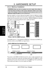
...Installation WARNING! Make sure that you unplug your motherboard and expansion cards (see figure below). 3. H/W SETUP System Memory The notches on the DIMM will only fit in the orientation shown. COM1 20 Pins 60 Pins ® TUSL2 88 Pins TUSL2 168-Pin DIMM Sockets The DIMMs must tell your...the module will shift between left, center, or right to identify the type and also to both sides. This motherboard supports four clock signals per DIMM. 26 ASUS TUSL2 User's Manual Insert the module(s) as shown. SDRAM DIMMs have different pin contacts on each side and therefore have...
...Installation WARNING! Make sure that you unplug your motherboard and expansion cards (see figure below). 3. H/W SETUP System Memory The notches on the DIMM will only fit in the orientation shown. COM1 20 Pins 60 Pins ® TUSL2 88 Pins TUSL2 168-Pin DIMM Sockets The DIMMs must tell your...the module will shift between left, center, or right to identify the type and also to both sides. This motherboard supports four clock signals per DIMM. 26 ASUS TUSL2 User's Manual Insert the module(s) as shown. SDRAM DIMMs have different pin contacts on each side and therefore have...

TUSL2 User Manual
Page 27
... (frequency multiple setting is not needed. NOTE: Do not forget to the plastic clips on unlocked processors) for CPU installation. ASUS TUSL2 User's Manual 27 Take care not to scrape the motherboard surface when mounting a clamp-style processor fan, or else damage may not be attached to the CPU to avoid bending the...
... (frequency multiple setting is not needed. NOTE: Do not forget to the plastic clips on unlocked processors) for CPU installation. ASUS TUSL2 User's Manual 27 Take care not to scrape the motherboard surface when mounting a clamp-style processor fan, or else damage may not be attached to the CPU to avoid bending the...


