
TR-DLS User Manual
Page 7
...for a 3.5" floppy disk drive (1) Support drivers and utilities (1) Socket 370 CPU Terminator (UMB type) (1) This Motherboard User's Manual ASUS TR-DLS User's Manual 7 If you discover damaged or missing items, contact your package is divided into the following sections: 1. INTRODUCTION Manual ...APPENDIX Optional items and general reference 1.2 Item Checklist Check that your retailer. (1) ASUS Motherboard (1) I/O Shield (1) Ribbon cable for master and slave IDE drives (1) 68-pin LVD SCSI ribbon cable for Ultra160/320 devices with Terminator (1) Ribbon cable for the included software...
...for a 3.5" floppy disk drive (1) Support drivers and utilities (1) Socket 370 CPU Terminator (UMB type) (1) This Motherboard User's Manual ASUS TR-DLS User's Manual 7 If you discover damaged or missing items, contact your package is divided into the following sections: 1. INTRODUCTION Manual ...APPENDIX Optional items and general reference 1.2 Item Checklist Check that your retailer. (1) ASUS Motherboard (1) I/O Shield (1) Ribbon cable for master and slave IDE drives (1) 68-pin LVD SCSI ribbon cable for Ultra160/320 devices with Terminator (1) Ribbon cable for the included software...
TR-DLS User Manual
Page 8
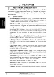
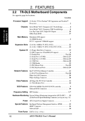
... through the onboard dual-channel Ultra160/320 SCSI connectors. • ATA-100 IDE Support: Comes with an onboard PCI Bus Master IDE controller with two connectors that require flexible configurations. FEATURES Specifications 2. FEATURES 2.1 ASUS TR-DLS Motherboard The ASUS TR-DLS motherboard is designed for additional peripherals 8 ASUS TR-DLS User's Manual Powered by dual Intel® Pentium® III...
... through the onboard dual-channel Ultra160/320 SCSI connectors. • ATA-100 IDE Support: Comes with an onboard PCI Bus Master IDE controller with two connectors that require flexible configurations. FEATURES Specifications 2. FEATURES 2.1 ASUS TR-DLS Motherboard The ASUS TR-DLS motherboard is designed for additional peripherals 8 ASUS TR-DLS User's Manual Powered by dual Intel® Pentium® III...
TR-DLS User Manual
Page 9
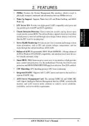
...over the motherboard. Provides boot block write protection, and HD/SCSI/MO/ZIP/CD/Floppy boot selection. ASUS TR-DLS User's Manual 9 The onboard battery supports detection even when normal power is removed and through the onboard hardware ASUS ASIC. • Enhanced ACPI: Programmable BIOS (Flash EEPROM...and systerm voltages, temperatures, and fan status through a new design, battery drain is used for a separate IOAPIC chip. • ASUS Server Management Card: The optional ASMC-LE and ASMC-ME cards support Intelligent Platform Management Interface (IPMI), system health monitor, and LAN ...
...over the motherboard. Provides boot block write protection, and HD/SCSI/MO/ZIP/CD/Floppy boot selection. ASUS TR-DLS User's Manual 9 The onboard battery supports detection even when normal power is removed and through the onboard hardware ASUS ASIC. • Enhanced ACPI: Programmable BIOS (Flash EEPROM...and systerm voltages, temperatures, and fan status through a new design, battery drain is used for a separate IOAPIC chip. • ASUS Server Management Card: The optional ASMC-LE and ASMC-ME cards support Intelligent Platform Management Interface (IPMI), system health monitor, and LAN ...
TR-DLS User Manual
Page 10
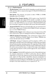
...UltraPerformance: Onboard Ultra160/320 (depending on model) dual channel SCSI controller can handle rates up to 160MB/s or 320MB/s. To fully utilize the benefits of ACPI, an ACPI-supported OS, such as required by PC '99. 10 ASUS TR-DLS User's Manual The new SDG2.0 requirements for systems and components... are not wasted. (Ultra160/320 SCSI cables have twisted pairs compared to flat ribbon cables used . • New Compliancy: Both ...
...UltraPerformance: Onboard Ultra160/320 (depending on model) dual channel SCSI controller can handle rates up to 160MB/s or 320MB/s. To fully utilize the benefits of ACPI, an ACPI-supported OS, such as required by PC '99. 10 ASUS TR-DLS User's Manual The new SDG2.0 requirements for systems and components... are not wasted. (Ultra160/320 SCSI cables have twisted pairs compared to flat ribbon cables used . • New Compliancy: Both ...
TR-DLS User Manual
Page 12
...-XL PCI VGA Controller 11 (1) VGA Monitor Port 24 SCSI Features LSI 64-bit 66MHz Ultra160/320 SCSI controller 9 Onboard SCSI Connectors 10 Frequency Setting DIP Switches 3, 7 Hardware Monitoring System Voltage Monitoring (integrated in ASUS ASIC) ....... 12 (4) Fan Power & Speed Monitoring Connectors... (see layout on p. 14) Power ATX 24-pin Power Supply Connector 1 Special Features Intelligent Platform Management Interface (IPMI 15 eRMC Connector 16 Onboard LED 14 Form Factor EATX (12 in .) 12 ASUS TR-DLS User...
...-XL PCI VGA Controller 11 (1) VGA Monitor Port 24 SCSI Features LSI 64-bit 66MHz Ultra160/320 SCSI controller 9 Onboard SCSI Connectors 10 Frequency Setting DIP Switches 3, 7 Hardware Monitoring System Voltage Monitoring (integrated in ASUS ASIC) ....... 12 (4) Fan Power & Speed Monitoring Connectors... (see layout on p. 14) Power ATX 24-pin Power Supply Connector 1 Special Features Intelligent Platform Management Interface (IPMI 15 eRMC Connector 16 Onboard LED 14 Form Factor EATX (12 in .) 12 ASUS TR-DLS User...
TR-DLS User Manual
Page 14
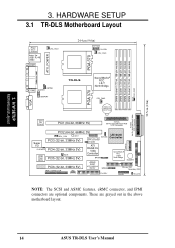
...PGA 370 PARALLEL PORT ATX_POWER KBPWR COM2 CHASSIS USBPORT TR-DLS ServerWorks® RCC LE-T North Bridge CPU_FAN2 PGA 370 VGA CR2032 3V Lithium Cell CMOS Power 01 23 45 67 SCSI-B 68-Pin Ultra160/Ultra2-Wide SCSI Connector Intel Fast Ethernet PCI1 (64-bit, 66MHz ... Monitor BPSMB Primary IDE1 Secondary IDE2 eRMC CONNECTOR IPMI FLOPPY PANEL HD_LED NOTE: The SCSI and ASMC features, eRMC connector, and IPMI connectors are grayed out in the above motherboard layout. 14 ASUS TR-DLS User's Manual H/W SETUP Motherboard Layout 3. These are optional components. 30.5cm (12in...
...PGA 370 PARALLEL PORT ATX_POWER KBPWR COM2 CHASSIS USBPORT TR-DLS ServerWorks® RCC LE-T North Bridge CPU_FAN2 PGA 370 VGA CR2032 3V Lithium Cell CMOS Power 01 23 45 67 SCSI-B 68-Pin Ultra160/Ultra2-Wide SCSI Connector Intel Fast Ethernet PCI1 (64-bit, 66MHz ... Monitor BPSMB Primary IDE1 Secondary IDE2 eRMC CONNECTOR IPMI FLOPPY PANEL HD_LED NOTE: The SCSI and ASMC features, eRMC connector, and IPMI connectors are grayed out in the above motherboard layout. 14 ASUS TR-DLS User's Manual H/W SETUP Motherboard Layout 3. These are optional components. 30.5cm (12in...
TR-DLS User Manual
Page 15
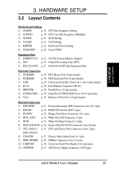
...) 4) WOL_CON p. 33 Wake-On-LAN Connector (3-pin) 5) WOR p. 33 Wake-On-Ring Connector (2-pin) 6) SCSI-A/SCSI-B p. 34 68-pin Ultra160 SCSI Connectors (two 68-pin) 7) CPU_FAN1/2 p. 35 CPU and Chassis Fan Connectors (four 3-pin) CHA_FAN1/2 8) CHASSIS ...p. 33 Chassis Open Alarm Lead (4-1 pin) 9) SMB, BPSMB p. 36 SMBus Connectors (two 6-1 pins) 10 USBPORT p. 36 Universal Serial Port Header (10-1pin male) 11) ATXPWR p. 37 ATX Power Supply Connector (20/24-pin) ASUS TR-DLS...
...) 4) WOL_CON p. 33 Wake-On-LAN Connector (3-pin) 5) WOR p. 33 Wake-On-Ring Connector (2-pin) 6) SCSI-A/SCSI-B p. 34 68-pin Ultra160 SCSI Connectors (two 68-pin) 7) CPU_FAN1/2 p. 35 CPU and Chassis Fan Connectors (four 3-pin) CHA_FAN1/2 8) CHASSIS ...p. 33 Chassis Open Alarm Lead (4-1 pin) 9) SMB, BPSMB p. 36 SMBus Connectors (two 6-1 pins) 10 USBPORT p. 36 Universal Serial Port Header (10-1pin male) 11) ATXPWR p. 37 ATX Power Supply Connector (20/24-pin) ASUS TR-DLS...
TR-DLS User Manual
Page 16
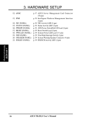
HARDWARE SETUP 12) eRMC p. 37 ASUS Server Management Card Connector (50-pin) 13) IPMI p. 38 Intelligent Platform Management Interface (4-pin) 14) NIC (PANEL) p. 38 NIC Activity LED (2-pin) 15) STATUS (PANEL) p. ... Lead (3-1 pin) 19) NMI (PANEL) p. 39 Non-Mask Interrupt Switch (2-pin) 20) SPEAKER (PANEL) p. 39 System Warning Speaker Connector (4-pin) 21) IDELED (PANEL) p. 39 IDE/SCSI Activity LED (2-pin) 3. H/W SETUP Motherboard Settings 16 ASUS TR-DLS User's Manual 3.
HARDWARE SETUP 12) eRMC p. 37 ASUS Server Management Card Connector (50-pin) 13) IPMI p. 38 Intelligent Platform Management Interface (4-pin) 14) NIC (PANEL) p. 38 NIC Activity LED (2-pin) 15) STATUS (PANEL) p. ... Lead (3-1 pin) 19) NMI (PANEL) p. 39 Non-Mask Interrupt Switch (2-pin) 20) SPEAKER (PANEL) p. 39 System Warning Speaker Connector (4-pin) 21) IDELED (PANEL) p. 39 IDE/SCSI Activity LED (2-pin) 3. H/W SETUP Motherboard Settings 16 ASUS TR-DLS User's Manual 3.
TR-DLS User Manual
Page 21
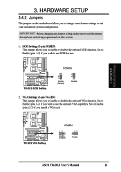
H/W SETUP Motherboard Settings 3. IMPORTANT! TR-DLS TR-DLS VGA Setting VGAEN 12 Enable (Default) 23 Disable ASUS TR-DLS User's Manual 21 3. Set to Enable (pins 1-2) if you to use SCSI devices. SCSI Settings (3-pin SCSIEN) This jumper allows you wish to enable or disable the onboard SCSI function. TR-DLS TR-DLS SCSI Setting SCSIEN 2 1 Enable (Default) 3 2 Disable 2. HARDWARE SETUP 3.4.2 Jumpers The jumpers on the...
H/W SETUP Motherboard Settings 3. IMPORTANT! TR-DLS TR-DLS VGA Setting VGAEN 12 Enable (Default) 23 Disable ASUS TR-DLS User's Manual 21 3. Set to Enable (pins 1-2) if you to use SCSI devices. SCSI Settings (3-pin SCSIEN) This jumper allows you wish to enable or disable the onboard SCSI function. TR-DLS TR-DLS SCSI Setting SCSIEN 2 1 Enable (Default) 3 2 Disable 2. HARDWARE SETUP 3.4.2 Jumpers The jumpers on the...
TR-DLS User Manual
Page 27
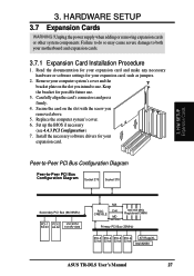
... Bus (66/33MHz) PCI-1 PCI-2 LSI SCSI 64-bit 64-bit 1010R/1030 MA RCC CNB30LE Cntl MD 100/133MHz 100/133 MHz Registered DIMM Primary PCI Bus (33MHz) PCI-3 PCI-4 PCI-5 PCI-6 ATI RageXL 32-bit 32-bit 32-bit 32-bit Intel 82550 ASUS TR-DLS User's Manual 27 Read the documentation...
... Bus (66/33MHz) PCI-1 PCI-2 LSI SCSI 64-bit 64-bit 1010R/1030 MA RCC CNB30LE Cntl MD 100/133MHz 100/133 MHz Registered DIMM Primary PCI Bus (33MHz) PCI-3 PCI-4 PCI-5 PCI-6 ATI RageXL 32-bit 32-bit 32-bit 32-bit Intel 82550 ASUS TR-DLS User's Manual 27 Read the documentation...
TR-DLS User Manual
Page 32
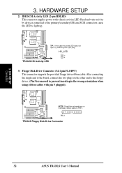
... 5 is removed to PIN 1. H/W SETUP Connectors 32 ASUS TR-DLS User's Manual 3. HD_LED + TR-DLS HD Activity LED 3) Floppy Disk Drive Connector (34-1 pin FLOPPY) This connector supports the provided floppy drive ribbon cable. Read and write activity by devices connected to the primary/secondary IDE and SCSI connectors cause the LED to the chassis activity...
... 5 is removed to PIN 1. H/W SETUP Connectors 32 ASUS TR-DLS User's Manual 3. HD_LED + TR-DLS HD Activity LED 3) Floppy Disk Drive Connector (34-1 pin FLOPPY) This connector supports the provided floppy drive ribbon cable. Read and write activity by devices connected to the primary/secondary IDE and SCSI connectors cause the LED to the chassis activity...
TR-DLS User Manual
Page 34
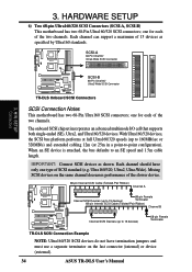
...last connector (internal) or device (external). 34 ASUS TR-DLS User's Manual H/W SETUP Connectors 34 68 TR-DLS Onboard SCSI Connectors SCSI Connection Notes This motherboard has two 68-Pin Ultra160 SCSI connectors; With Ultra160/320 devices, the SCSI bus platform performs at full Ultra160/320 speeds (up... in a point-to an SE speed and 1.5m cable length. SCSI-A 68-Pin Ultra160/ 1 35 Ultra2-Wide SCSI Connector TR-DLS 34 1 68 35 SCSI-B 68-Pin Ultra160/ Ultra2-Wide SCSI Connector 3. The onboard SCSI chipset incorporates an advanced multimode I/O cell that supports both single-ended ...
...last connector (internal) or device (external). 34 ASUS TR-DLS User's Manual H/W SETUP Connectors 34 68 TR-DLS Onboard SCSI Connectors SCSI Connection Notes This motherboard has two 68-Pin Ultra160 SCSI connectors; With Ultra160/320 devices, the SCSI bus platform performs at full Ultra160/320 speeds (up... in a point-to an SE speed and 1.5m cable length. SCSI-A 68-Pin Ultra160/ 1 35 Ultra2-Wide SCSI Connector TR-DLS 34 1 68 35 SCSI-B 68-Pin Ultra160/ Ultra2-Wide SCSI Connector 3. The onboard SCSI chipset incorporates an advanced multimode I/O cell that supports both single-ended ...
TR-DLS User Manual
Page 39
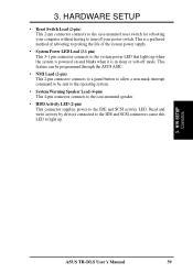
...case-mounted speaker. • HDD Activity LED (2-pin) This connector supplies power to the system power LED that lights up . 3. H/W SETUP Connectors ASUS TR-DLS User's Manual 39 HARDWARE SETUP • Reset Switch Lead (2-pin) This 2-pin connector connects to the case-mounted reset switch for rebooting your computer ...and blinks when it is in sleep or soft-off your power switch. 3. Read and write activity by devices connected to the IDE and SCSI connectors cause this LED to turn off mode. This is a preferred method of rebooting to prolong the life of the system power supply. ...
...case-mounted speaker. • HDD Activity LED (2-pin) This connector supplies power to the system power LED that lights up . 3. H/W SETUP Connectors ASUS TR-DLS User's Manual 39 HARDWARE SETUP • Reset Switch Lead (2-pin) This 2-pin connector connects to the case-mounted reset switch for rebooting your computer ...and blinks when it is in sleep or soft-off your power switch. 3. Read and write activity by devices connected to the IDE and SCSI connectors cause this LED to turn off mode. This is a preferred method of rebooting to prolong the life of the system power supply. ...
TR-DLS User Manual
Page 40
External SCSI devices (starting with the last device on the front panel of the system case lights up. If the monitor complies with ATX power supplies. 40 ASUS TR-DLS User's Manual While the tests are off after the system LED does. Monitor b. For ATX power supplies, the system LED lights up or switch between...
External SCSI devices (starting with the last device on the front panel of the system case lights up. If the monitor complies with ATX power supplies. 40 ASUS TR-DLS User's Manual While the tests are off after the system LED does. Monitor b. For ATX power supplies, the system LED lights up or switch between...
TR-DLS User Manual
Page 59
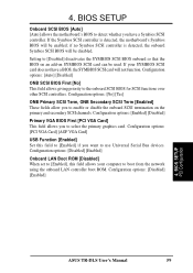
... LAN controller boot ROM. Configuration options: [PCI VGA Card] [AGP VGA Card] USB Function [Enabled] Set this field allows your SYMBIOS SCSI card does not have a Symbios SCSI controller. BIOS SETUP PCI Configuration ASUS TR-DLS User's Manual 59 BIOS SETUP Onboard SCSI BIOS [Auto] [Auto] allows the motherboard's BIOS to use Universal Serial Bus devices.
... LAN controller boot ROM. Configuration options: [PCI VGA Card] [AGP VGA Card] USB Function [Enabled] Set this field allows your SYMBIOS SCSI card does not have a Symbios SCSI controller. BIOS SETUP PCI Configuration ASUS TR-DLS User's Manual 59 BIOS SETUP Onboard SCSI BIOS [Auto] [Auto] allows the motherboard's BIOS to use Universal Serial Bus devices.

TR-DLS User Manual
Page 61
... < 4 Secs [Soft Off] When set to [Soft off], the ATX switch can be used as set up in sleep mode. This feature does not affect SCSI hard drives. BIOS SETUP Video Off Option [Suspend -> Off ] This field determines when to activate the video off button when pressed for monitor power management... the video display card if it supports the DPMS feature. [Blank Screen] only blanks the screen (use this user-configurable field. BIOS SETUP Power Menu ASUS TR-DLS User's Manual 61
... < 4 Secs [Soft Off] When set to [Soft off], the ATX switch can be used as set up in sleep mode. This feature does not affect SCSI hard drives. BIOS SETUP Video Off Option [Suspend -> Off ] This field determines when to activate the video off button when pressed for monitor power management... the video display card if it supports the DPMS feature. [Blank Screen] only blanks the screen (use this user-configurable field. BIOS SETUP Power Menu ASUS TR-DLS User's Manual 61
TR-DLS User Manual
Page 65
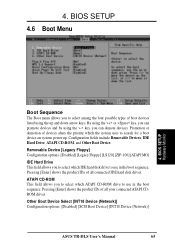
... [Enter] shows the product IDs of boot devices listed using the up . Other Boot Device Select [INT18 Device (Network)] Configuration options: [Disabled] [SCSI Boot Device] [INT18 Device (Network)] ASUS TR-DLS User's Manual 65 By using the key, you to select which the system uses to use in the boot sequence. Removable Device [Legacy...
... [Enter] shows the product IDs of boot devices listed using the up . Other Boot Device Select [INT18 Device (Network)] Configuration options: [Disabled] [SCSI Boot Device] [INT18 Device (Network)] ASUS TR-DLS User's Manual 65 By using the key, you to select which the system uses to use in the boot sequence. Removable Device [Legacy...
TR-DLS User Manual
Page 72
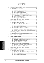
... 4.XX and 5.X Installations 89 III. Existing System Installation 77 II. Driver Installation Table of Contents 72 ASUS TR-DLS User's Manual New System Installation 78 C. LSI SCSI Driver Installation 81 A. LSI SCSI Driver Installation 86 A. LSI SCSI Driver Installation 90 A. Update Driver on an Existing System Installation ... 84 III. Building the SYMHISL Driver ... ATA100 Feature Under Windows 2000 85 5.3 Microsoft Windows XP Professional 86 5.4 Novell NetWare Server 86 I . Contents 5.1 Microsoft Windows NT Server 4.0 75 I . LSI SCSI Driver Installation 75 A.
... 4.XX and 5.X Installations 89 III. Existing System Installation 77 II. Driver Installation Table of Contents 72 ASUS TR-DLS User's Manual New System Installation 78 C. LSI SCSI Driver Installation 81 A. LSI SCSI Driver Installation 86 A. LSI SCSI Driver Installation 90 A. Update Driver on an Existing System Installation ... 84 III. Building the SYMHISL Driver ... ATA100 Feature Under Windows 2000 85 5.3 Microsoft Windows XP Professional 86 5.4 Novell NetWare Server 86 I . Contents 5.1 Microsoft Windows NT Server 4.0 75 I . LSI SCSI Driver Installation 75 A.

TR-DLS User Manual
Page 73
... 82550 Network Driver Installation 104 III. Driver Installation Table of Contents ASUS TR-DLS User's Manual 73 Building the SCO OpenServer BTLD Diskette ....... 96 B. ATI Rage XL Display Driver Installation 100 5.7 SCO UnixWare Server 100 I . Intel 82550 Network Driver Installation 103 III. LSI SCSI Driver Installation 104 II. ATI Rage XL Display Driver Installation...
... 82550 Network Driver Installation 104 III. Driver Installation Table of Contents ASUS TR-DLS User's Manual 73 Building the SCO OpenServer BTLD Diskette ....... 96 B. ATI Rage XL Display Driver Installation 100 5.7 SCO UnixWare Server 100 I . Intel 82550 Network Driver Installation 103 III. LSI SCSI Driver Installation 104 II. ATI Rage XL Display Driver Installation...
TR-DLS User Manual
Page 75
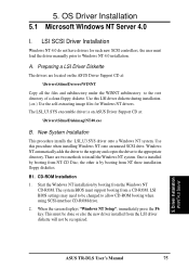
...SCSI-interface CD-ROM drive. 2. The system BIOS must be done or else the new driver installed from NT three installation floppy diskettes. A. Start the Windows NT installation by booting from the LSI driver diskette will not be changed to the appropriate directory. Driver Installation WinNT4.0 Server ASUS TR-DLS... User's Manual 75 OS Driver Installation 5.1 Microsoft Windows NT Server 4.0 I. There are located on ASUS Driver Support CD at : \Drivers\Sdms\Drivers\WINNT Copy all the ...
...SCSI-interface CD-ROM drive. 2. The system BIOS must be done or else the new driver installed from NT three installation floppy diskettes. A. Start the Windows NT installation by booting from the LSI driver diskette will not be changed to the appropriate directory. Driver Installation WinNT4.0 Server ASUS TR-DLS... User's Manual 75 OS Driver Installation 5.1 Microsoft Windows NT Server 4.0 I. There are located on ASUS Driver Support CD at : \Drivers\Sdms\Drivers\WINNT Copy all the ...