Series User Manual
Page 13
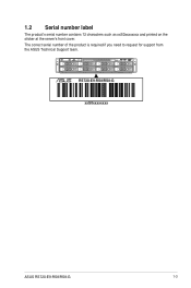
1.2 Serial number label The product's serial number contains 12 characters such as xxS0xxxxxxxx and printed on the sticker at the server's front cover. The correct serial number of the product is required if you need to request for support from the ASUS Technical Support team. 4 3 2 1 RESET RS720-E9-RS8/RS8-G xxS0xxxxxxxx ASUS RS720-E9-RS8/RS8-G 1-3
1.2 Serial number label The product's serial number contains 12 characters such as xxS0xxxxxxxx and printed on the sticker at the server's front cover. The correct serial number of the product is required if you need to request for support from the ASUS Technical Support team. 4 3 2 1 RESET RS720-E9-RS8/RS8-G xxS0xxxxxxxx ASUS RS720-E9-RS8/RS8-G 1-3

Series User Manual
Page 14
...® Scalable Processors Family Series plus other latest technologies through the chipsets onboard. 1.3 System specifications The ASUS RS720-E9-RS8/RS8-G features the ASUS Z11PP-D24 server board. Model Name RS720-E9-RS8 RS720-E9-RS8-G Motherboard Z11PP-D24 Processor Support 2 x Socket P0 (LGA 3647) 1st Gen Intel® Xeon&#... Channel) Intel® Optane™ DC persistent memory (DCPMM) * 2933MHz will drop to 2666MHz when using 2DPC configurations ** Refer to ASUS server AVL for the latest update Memory Size 4GB, 8GB, 12GB, 32GB, 64GB (RDIMM) 64GB, 128GB, 256GB (RDIMM 3DS) 32GB...
...® Scalable Processors Family Series plus other latest technologies through the chipsets onboard. 1.3 System specifications The ASUS RS720-E9-RS8/RS8-G features the ASUS Z11PP-D24 server board. Model Name RS720-E9-RS8 RS720-E9-RS8-G Motherboard Z11PP-D24 Processor Support 2 x Socket P0 (LGA 3647) 1st Gen Intel® Xeon&#... Channel) Intel® Optane™ DC persistent memory (DCPMM) * 2933MHz will drop to 2666MHz when using 2DPC configurations ** Refer to ASUS server AVL for the latest update Memory Size 4GB, 8GB, 12GB, 32GB, 64GB (RDIMM) 64GB, 128GB, 256GB (RDIMM 3DS) 32GB...

Series User Manual
Page 15
Model Name I = internal A or S will be hotswappable Storage Bays PCIe NVMe Riser Card & Cable Networking LAN Graphic VGA I/O Ports, Switches, and LEDs RS720-E9-RS8 RS720-E9-RS8-G Front bays: 8 x 2.5"/3.5" Hot-swap Storage Device Bays (4 x SATA/SAS + 4 x SATA/SAS/NVMe) Rear bays: Internal storage: 2 x 2.5" Hot-swap drive bays (2 x SATA/NVMe) (optional) Internal storage: 2 x M.2 (... switch/LED 1 x Location switch/LED 1 x Reset switch 1 x Storage device access LED 1 x Message LED LAN 1-4 LEDs * LAN 3-4 for Mezzanine card use (continued on the next page) ASUS RS720-E9-RS8/RS8-G 1-5
Model Name I = internal A or S will be hotswappable Storage Bays PCIe NVMe Riser Card & Cable Networking LAN Graphic VGA I/O Ports, Switches, and LEDs RS720-E9-RS8 RS720-E9-RS8-G Front bays: 8 x 2.5"/3.5" Hot-swap Storage Device Bays (4 x SATA/SAS + 4 x SATA/SAS/NVMe) Rear bays: Internal storage: 2 x 2.5" Hot-swap drive bays (2 x SATA/NVMe) (optional) Internal storage: 2 x M.2 (... switch/LED 1 x Location switch/LED 1 x Reset switch 1 x Storage device access LED 1 x Message LED LAN 1-4 LEDs * LAN 3-4 for Mezzanine card use (continued on the next page) ASUS RS720-E9-RS8/RS8-G 1-5

Series User Manual
Page 17
... middle part includes the I/O shield with easily accessible features. 1.4 Front panel features The barebone server displays a simple yet stylish front panel with openings for troubleshooting. ASUS RS720-E9-RS8/RS8-G 1-7 The power and reset buttons, LED indicators, and two USB ports are located on the motherboard.
... middle part includes the I/O shield with easily accessible features. 1.4 Front panel features The barebone server displays a simple yet stylish front panel with openings for troubleshooting. ASUS RS720-E9-RS8/RS8-G 1-7 The power and reset buttons, LED indicators, and two USB ports are located on the motherboard.

Series User Manual
Page 19
... you need to any of the USB ports on the system for proper heat dissipation. ASUS Z11PP-D24 Server Board 3. Connect a USB floppy disk drive to use a floppy disk. RS720-E9-RS8 (without rear bay model) 1. SATA/SAS back panel 5. 8 x 2.5"/3.5" storage device trays 6. WARNING HAZARDOUS MOVING PARTS KEEP FINGERS AND OTHER BODY PARTS AWAY ASUS RS720-E9-RS8/RS8-G 1-9
... you need to any of the USB ports on the system for proper heat dissipation. ASUS Z11PP-D24 Server Board 3. Connect a USB floppy disk drive to use a floppy disk. RS720-E9-RS8 (without rear bay model) 1. SATA/SAS back panel 5. 8 x 2.5"/3.5" storage device trays 6. WARNING HAZARDOUS MOVING PARTS KEEP FINGERS AND OTHER BODY PARTS AWAY ASUS RS720-E9-RS8/RS8-G 1-9

Series User Manual
Page 21
GPU fans 4. System fans 5. SATA/SAS back panel 6. 8 x 2.5"/3.5" storage device trays 7. Front panel (hidden) 8. ASUS Z11PP-D24 Server Board 3. A protection film is pre-attached to use a floppy disk. Asset tag (hidden) The barebone server does not include a floppy ... drive to any of the USB ports on the system for proper heat dissipation. WARNING HAZARDOUS MOVING PARTS KEEP FINGERS AND OTHER BODY PARTS AWAY ASUS RS720-E9-RS8/RS8-G 1-11 RS720-E9-RS8-G 1 34 2 1 34 2 1. Please remove the protection film before turning on the front or rear panel if you need to the front ...
GPU fans 4. System fans 5. SATA/SAS back panel 6. 8 x 2.5"/3.5" storage device trays 7. Front panel (hidden) 8. ASUS Z11PP-D24 Server Board 3. A protection film is pre-attached to use a floppy disk. Asset tag (hidden) The barebone server does not include a floppy ... drive to any of the USB ports on the system for proper heat dissipation. WARNING HAZARDOUS MOVING PARTS KEEP FINGERS AND OTHER BODY PARTS AWAY ASUS RS720-E9-RS8/RS8-G 1-11 RS720-E9-RS8-G 1 34 2 1 34 2 1. Please remove the protection film before turning on the front or rear panel if you need to the front ...

Series User Manual
Page 23
... Status Description OFF No link GREEN Linked BLINKING Data activity SPEED LED Status Description OFF 10 Mbps connection ORANGE 100 Mbps connection GREEN 1 Gbps connection ASUS RS720-E9-RS8/RS8-G 1-13
... Status Description OFF No link GREEN Linked BLINKING Data activity SPEED LED Status Description OFF 10 Mbps connection ORANGE 100 Mbps connection GREEN 1 Gbps connection ASUS RS720-E9-RS8/RS8-G 1-13

Series User Manual
Page 25
... matching the BIOS public key token The BIOS OEM public key of the BIOS was not called by verifying MAC (continued on the next page) ASUS RS720-E9-RS8/RS8-G 1-15 HVB validation failure for slave to complete pending transactions Unable to kill current transaction on host One of: Illegal command An SMBus transaction collision...
... matching the BIOS public key token The BIOS OEM public key of the BIOS was not called by verifying MAC (continued on the next page) ASUS RS720-E9-RS8/RS8-G 1-15 HVB validation failure for slave to complete pending transactions Unable to kill current transaction on host One of: Illegal command An SMBus transaction collision...

Series User Manual
Page 27
... BIOS Setup Utility password verify BIOS Setup Utility start BIOS Setup Utility input wait Ready to boot event Legacy boot event APIC mode PIC mode ASUS RS720-E9-RS8/RS8-G 1-17
... BIOS Setup Utility password verify BIOS Setup Utility start BIOS Setup Utility input wait Ready to boot event Legacy boot event APIC mode PIC mode ASUS RS720-E9-RS8/RS8-G 1-17

Series User Manual
Page 31
...with the cap on the LGA 3647 socket. • The product warranty does not cover damage to the PnP cap/socket contacts/motherboard components. ASUS RS720-E9-RS8/RS8-G 2-3 Remove the air duct screw (A), remove the air ducts (B), and then remove the PnP caps (C) from incorrect CPU installation/removal, ...or misplacement/loss/incorrect removal of the motherboard, ensure that the PnP cap is on the LGA 3647 socket. ASUS will process Return Merchandise Authorization (RMA) requests only if the motherboard comes with the PnP cap on the socket and the socket contacts...
...with the cap on the LGA 3647 socket. • The product warranty does not cover damage to the PnP cap/socket contacts/motherboard components. ASUS RS720-E9-RS8/RS8-G 2-3 Remove the air duct screw (A), remove the air ducts (B), and then remove the PnP caps (C) from incorrect CPU installation/removal, ...or misplacement/loss/incorrect removal of the motherboard, ensure that the PnP cap is on the LGA 3647 socket. ASUS will process Return Merchandise Authorization (RMA) requests only if the motherboard comes with the PnP cap on the socket and the socket contacts...

Series User Manual
Page 33
Reinstall the air ducts (A), and then secure the air duct with the air duct screw removed in step 2 (B). ASUS RS720-E9-RS8/RS8-G 2-5 6.
Reinstall the air ducts (A), and then secure the air duct with the air duct screw removed in step 2 (B). ASUS RS720-E9-RS8/RS8-G 2-5 6.

Series User Manual
Page 35
...and 128GB, 256GB, and 512GB DCPMMs into the DIMM sockets using the memory configurations in this section. • Refer to ASUS Server AVL for 1 CPU Configuration 1 CPU Configuration (must be on CPU1) DIMM_A2 DIMM_A1 DIMM_B2 DIMM_B1 DIMM_C2 DIMM_C1 1 DIMM &#... 6 DIMMs • • • 8 DIMMs • • • • 12 DIMMs • • • • • • ASUS RS720-E9-RS8/RS8-G 2-7 2.3.2 Memory Configurations You may install 4GB, 8GB, 12GB, and 32GB RDIMMs; 64GB and 128GB RDIMMs (3DS); 32GB, 64GB, and 128GB LRDIMMs; 64GB, 128GB, and 256GB...
...and 128GB, 256GB, and 512GB DCPMMs into the DIMM sockets using the memory configurations in this section. • Refer to ASUS Server AVL for 1 CPU Configuration 1 CPU Configuration (must be on CPU1) DIMM_A2 DIMM_A1 DIMM_B2 DIMM_B1 DIMM_C2 DIMM_C1 1 DIMM &#... 6 DIMMs • • • 8 DIMMs • • • • 12 DIMMs • • • • • • ASUS RS720-E9-RS8/RS8-G 2-7 2.3.2 Memory Configurations You may install 4GB, 8GB, 12GB, and 32GB RDIMMs; 64GB and 128GB RDIMMs (3DS); 32GB, 64GB, and 128GB LRDIMMs; 64GB, 128GB, and 256GB...

Series User Manual
Page 37
... DCPMM DRAM 1 DRAM1 AD+MM DCPMM DRAM 3 DRAM3 AD DCPMM DRAM 1 DRAM 1 DRAM 1 DRAM1 AD - MEMORY MODE AD+MM - MIXED MODE DRAM1 - DC PERSISTENT MEMORY ASUS RS720-E9-RS8/RS8-G 2-9
... DCPMM DRAM 1 DRAM1 AD+MM DCPMM DRAM 3 DRAM3 AD DCPMM DRAM 1 DRAM 1 DRAM 1 DRAM1 AD - MEMORY MODE AD+MM - MIXED MODE DRAM1 - DC PERSISTENT MEMORY ASUS RS720-E9-RS8/RS8-G 2-9

Series User Manual
Page 43
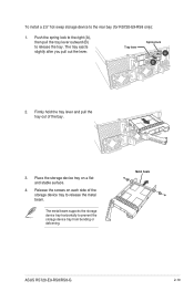
...(8) 2.5" or 3.5" hot-swap storage devices on the front panel, and two (2) additional 2.5" hot-swap storage devices on a flat and stable surface. 4. ASUS RS720-E9-RS8/RS8-G 2-15 Push the spring lock to the right (A), then pull the tray lever outward (B) to the front panel: 1. Place the tray on the rear ...panel (for RS720-E9-RS8 only). To install a 2.5" hot-swap storage device to release the tray. The tray ejects slightly after you pull out the lever. Prepare the ...
...(8) 2.5" or 3.5" hot-swap storage devices on the front panel, and two (2) additional 2.5" hot-swap storage devices on a flat and stable surface. 4. ASUS RS720-E9-RS8/RS8-G 2-15 Push the spring lock to the right (A), then pull the tray lever outward (B) to the front panel: 1. Place the tray on the rear ...panel (for RS720-E9-RS8 only). To install a 2.5" hot-swap storage device to release the tray. The tray ejects slightly after you pull out the lever. Prepare the ...

Series User Manual
Page 45
Prepare the 3.5" hot-swap storage device and the bundled set of the bay. 3. Push the spring lock to the right (A), then pull the tray lever outward (B) to the front panel: 1. Firmly hold the tray lever and pull the tray out of screws. Place the tray on a flat and stable surface. 4. Tray lever Spring lock 2. ASUS RS720-E9-RS8/RS8-G 2-17 The tray ejects slightly after you pull out the lever. To install a 3.5" hot-swap storage device to release the tray.
Prepare the 3.5" hot-swap storage device and the bundled set of the bay. 3. Push the spring lock to the right (A), then pull the tray lever outward (B) to the front panel: 1. Firmly hold the tray lever and pull the tray out of screws. Place the tray on a flat and stable surface. 4. Tray lever Spring lock 2. ASUS RS720-E9-RS8/RS8-G 2-17 The tray ejects slightly after you pull out the lever. To install a 3.5" hot-swap storage device to release the tray.
Series User Manual
Page 47
... ejects slightly after you pull out the lever. Place the storage device tray on each side of the bay. 3. Tray lever Spring lock 2. Metal beam ASUS RS720-E9-RS8/RS8-G 2-19 Push the spring lock to the right (A), then pull the tray lever outward (B) to release the metal beam. Release the screws on a flat and...
... ejects slightly after you pull out the lever. Place the storage device tray on each side of the bay. 3. Tray lever Spring lock 2. Metal beam ASUS RS720-E9-RS8/RS8-G 2-19 Push the spring lock to the right (A), then pull the tray lever outward (B) to release the metal beam. Release the screws on a flat and...
Series User Manual
Page 49
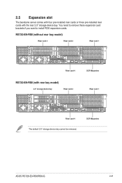
OCP Mezzanine ASUS RS720-E9-RS8/RS8-G 2-21 RS720-E9-RS8 (without rear bay model) Riser card 3 Riser card 2 Riser card 1 Riser card 4 RS720-E9-RS8 (with the rear 2.5" storage device bay. You need to remove these expansion card brackets if you want to install PCIE expansion cards. 2.5 Expansion slot The barebone server comes with four pre-installed riser cards or three pre-installed riser cards with rear bay model) 2.5" storage device bay Riser card 2 OCP Mezzanine Riser card 1 Riser card 4 The default 2.5" storage device bay cannot be removed.
OCP Mezzanine ASUS RS720-E9-RS8/RS8-G 2-21 RS720-E9-RS8 (without rear bay model) Riser card 3 Riser card 2 Riser card 1 Riser card 4 RS720-E9-RS8 (with the rear 2.5" storage device bay. You need to remove these expansion card brackets if you want to install PCIE expansion cards. 2.5 Expansion slot The barebone server comes with four pre-installed riser cards or three pre-installed riser cards with rear bay model) 2.5" storage device bay Riser card 2 OCP Mezzanine Riser card 1 Riser card 4 The default 2.5" storage device bay cannot be removed.
Series User Manual
Page 51
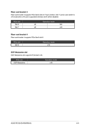
PCIe slot Slot 6 Slot 7 Operation mode x8 N/A x8 x16 Riser card bracket 4 Riser card bracket 4 supports PCIe Gen3 slot 8. Slot 7 can be auto-switch to bottom. PCIe slot OCP Mezzanine Operation mode x16 ASUS RS720-E9-RS8/RS8-G 2-23 PCIe slot Slot 8 Operation mode x16 OCP Mezzanine slot OCP Mezzanine slot supports PCIe Gen3 x16. Riser card bracket 3 Riser card bracket 3 supports PCIe Gen3 slots 6-7 top to x16 mode when x16 card is populated whereas slot 6 will be disabled.
PCIe slot Slot 6 Slot 7 Operation mode x8 N/A x8 x16 Riser card bracket 4 Riser card bracket 4 supports PCIe Gen3 slot 8. Slot 7 can be auto-switch to bottom. PCIe slot OCP Mezzanine Operation mode x16 ASUS RS720-E9-RS8/RS8-G 2-23 PCIe slot Slot 8 Operation mode x16 OCP Mezzanine slot OCP Mezzanine slot supports PCIe Gen3 x16. Riser card bracket 3 Riser card bracket 3 supports PCIe Gen3 slots 6-7 top to x16 mode when x16 card is populated whereas slot 6 will be disabled.
Series User Manual
Page 53
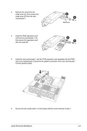
Remove the screw from the metal cover (A), then remove the metal cover (B) from the riser card bracket 1. 4. ASUS RS720-E9-RS8/RS8-G 2-25 Metal cover 5. 3. Install the riser card bracket 1 and the PCIE expansion card assembly into the riser card bracket 1 (A), then secure the expansion card with the screw removed in place. 6. Secure the riser card bracket 1 to the chassis with the screw (B). Ensure that the golden connectors of the riser card bracket 1 is firmly seated in step 1. Install the PCIE expansion card into the PCIE1 slot on the motherboard.
Remove the screw from the metal cover (A), then remove the metal cover (B) from the riser card bracket 1. 4. ASUS RS720-E9-RS8/RS8-G 2-25 Metal cover 5. 3. Install the riser card bracket 1 and the PCIE expansion card assembly into the riser card bracket 1 (A), then secure the expansion card with the screw removed in place. 6. Secure the riser card bracket 1 to the chassis with the screw (B). Ensure that the golden connectors of the riser card bracket 1 is firmly seated in step 1. Install the PCIE expansion card into the PCIE1 slot on the motherboard.

Series User Manual
Page 55
Install the PCIE expansion card into the PCIE3 slot on the motherboard. Install the riser card bracket 2 and the PCIE expansion card assembly into the riser card bracket 2 (A), then secure the expansion card with the screws removed in step 1. Secure the riser card bracket 2 to the chassis with the screw (B). 6. ASUS RS720-E9-RS8/RS8-G 2-27 Ensure that the golden connectors of the riser card bracket 2 is firmly seated in step 2. 8. Secure the riser card bracket 2 to the motherboard with the screw removed in place. 7. 5.
Install the PCIE expansion card into the PCIE3 slot on the motherboard. Install the riser card bracket 2 and the PCIE expansion card assembly into the riser card bracket 2 (A), then secure the expansion card with the screws removed in step 1. Secure the riser card bracket 2 to the chassis with the screw (B). 6. ASUS RS720-E9-RS8/RS8-G 2-27 Ensure that the golden connectors of the riser card bracket 2 is firmly seated in step 2. 8. Secure the riser card bracket 2 to the motherboard with the screw removed in place. 7. 5.


