
Series User Manual
Page 6
... Change Smbios Event Log Settings 5-38 5.8.2 View Smbios Event Log 5-38 5.9 Server Mgmt menu 5-39 5.10 Security menu 5-40 5.11 Boot menu 5-42 5.12 Tool menu 5-43 5.13 Save & Exit menu 5-43 Chapter 6: RAID Configuration 6.1 Setting up RAID 6-2 6.1.1 RAID definitions 6-2 6.1.2 Installing hard disk drives 6-3 6.1.3 Setting the RAID item in BIOS 6-3 6.1.4 RAID configuration utilities 6-3 6.2 Intel® Rapid Storage Technology enterprise SATA/SSATA Option ROM Utility 6-4 6.2.1 Creating a RAID set 6-5 6.2.2 Deleting a RAID set 6-7 6.2.3 6.2.4 Resetting disks to Non-RAID...
... Change Smbios Event Log Settings 5-38 5.8.2 View Smbios Event Log 5-38 5.9 Server Mgmt menu 5-39 5.10 Security menu 5-40 5.11 Boot menu 5-42 5.12 Tool menu 5-43 5.13 Save & Exit menu 5-43 Chapter 6: RAID Configuration 6.1 Setting up RAID 6-2 6.1.1 RAID definitions 6-2 6.1.2 Installing hard disk drives 6-3 6.1.3 Setting the RAID item in BIOS 6-3 6.1.4 RAID configuration utilities 6-3 6.2 Intel® Rapid Storage Technology enterprise SATA/SSATA Option ROM Utility 6-4 6.2.1 Creating a RAID set 6-5 6.2.2 Deleting a RAID set 6-7 6.2.3 6.2.4 Resetting disks to Non-RAID...

Series User Manual
Page 7
... Rapid Storage Technology enterprise (Windows 6-12 6.3.1 Creating a RAID set 6-13 6.3.2 Changing a Volume Type 6-15 6.3.3 Deleting a volume 6-16 6.3.4 Preferences 6-17 6.4 Intel® Virtual Raid on CPU in BIOS 6-18 6.4.1 Creating a RAID set 6-19 6.4.2 Deleting a RAID set 6-20 Chapter 7: Driver Installation 7.1 RAID driver installation 7-2 7.1.1 Creating a USB flash drive with RAID drive 7-2 7.1.2 Installing the RAID controller driver 7-2 7.2 Management applications and utilities installation 7-5 7.3 Running the Support DVD 7-5 7.4 Intel® chipset device software installation...
... Rapid Storage Technology enterprise (Windows 6-12 6.3.1 Creating a RAID set 6-13 6.3.2 Changing a Volume Type 6-15 6.3.3 Deleting a volume 6-16 6.3.4 Preferences 6-17 6.4 Intel® Virtual Raid on CPU in BIOS 6-18 6.4.1 Creating a RAID set 6-19 6.4.2 Deleting a RAID set 6-20 Chapter 7: Driver Installation 7.1 RAID driver installation 7-2 7.1.1 Creating a USB flash drive with RAID drive 7-2 7.1.2 Installing the RAID controller driver 7-2 7.2 Management applications and utilities installation 7-5 7.3 Running the Support DVD 7-5 7.4 Intel® chipset device software installation...
Series User Manual
Page 9
..., jumper settings, and connector locations. 5. Chapter 7: Driver Installation This chapter provides instructions for installing the necessary drivers for setting up, creating and configuring RAID sets using the available utilities. 7. ix Chapter 3: Installation Options This chapter describes how to change system settings through the BIOS Setup menus and describes the BIOS parameters. 6. Chapter 4: Motherboard Information This chapter gives information about the motherboard that you have to perform when installing or removing system components. 3. Chapter 6: RAID Configuration This...
..., jumper settings, and connector locations. 5. Chapter 7: Driver Installation This chapter provides instructions for installing the necessary drivers for setting up, creating and configuring RAID sets using the available utilities. 7. ix Chapter 3: Installation Options This chapter describes how to change system settings through the BIOS Setup menus and describes the BIOS parameters. 6. Chapter 4: Motherboard Information This chapter gives information about the motherboard that you have to perform when installing or removing system components. 3. Chapter 6: RAID Configuration This...
Series User Manual
Page 10
... information. 2. ASUS Control Center (ACC) user guide This manual tells how to complete a task. Refer to complete a task. ASUS websites The ASUS websites worldwide provide updated information for more keys simultaneously, the key names are linked with a plus sign (+). IMPORTANT: Instructions that you perform certain tasks properly, take note of the following sources for additional information, and for product and software updates. 1. Italics Used to...
... information. 2. ASUS Control Center (ACC) user guide This manual tells how to complete a task. Refer to complete a task. ASUS websites The ASUS websites worldwide provide updated information for more keys simultaneously, the key names are linked with a plus sign (+). IMPORTANT: Instructions that you perform certain tasks properly, take note of the following sources for additional information, and for product and software updates. 1. Italics Used to...

Series User Manual
Page 17
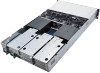
... a starting point for details. ASUS RS720-E9-RS8/RS8-G 1-7 The actual cause may vary from case to case. • Refer to section 1.7 LED information for the rear panel connectors on the front panel. Refer to the Q-Code table for troubleshooting. Asset tag Front panel LEDs & buttons USB 2.0 ports 4 3 2 1 RESET VGA port handle 8 x 2.5"/3.5" Drive Bays handle 1.5 Rear panel features The rear panel includes the expansion slots, system power sockets, and rear fans. 1.4 Front panel features The barebone server displays a simple yet stylish front panel with openings...
... a starting point for details. ASUS RS720-E9-RS8/RS8-G 1-7 The actual cause may vary from case to case. • Refer to section 1.7 LED information for the rear panel connectors on the front panel. Refer to the Q-Code table for troubleshooting. Asset tag Front panel LEDs & buttons USB 2.0 ports 4 3 2 1 RESET VGA port handle 8 x 2.5"/3.5" Drive Bays handle 1.5 Rear panel features The rear panel includes the expansion slots, system power sockets, and rear fans. 1.4 Front panel features The barebone server displays a simple yet stylish front panel with openings...

Series User Manual
Page 19
... any of the USB ports on the system for proper heat dissipation. WARNING HAZARDOUS MOVING PARTS KEEP FINGERS AND OTHER BODY PARTS AWAY ASUS RS720-E9-RS8/RS8-G 1-9 ASUS Z11PP-D24 Server Board 3. Front panel (hidden) 7. Asset tag (hidden) 1 34 2 1 34 2 The barebone server does not include a floppy disk drive. Redundant Power supply 2. Please remove the protection film before shipping. RS720-E9-RS8 (without rear bay model) 1. Connect a USB floppy disk drive to use a floppy disk. 1.6 Internal features The barebone server includes the basic...
... any of the USB ports on the system for proper heat dissipation. WARNING HAZARDOUS MOVING PARTS KEEP FINGERS AND OTHER BODY PARTS AWAY ASUS RS720-E9-RS8/RS8-G 1-9 ASUS Z11PP-D24 Server Board 3. Front panel (hidden) 7. Asset tag (hidden) 1 34 2 1 34 2 The barebone server does not include a floppy disk drive. Redundant Power supply 2. Please remove the protection film before shipping. RS720-E9-RS8 (without rear bay model) 1. Connect a USB floppy disk drive to use a floppy disk. 1.6 Internal features The barebone server includes the basic...

Series User Manual
Page 21
... server does not include a floppy disk drive. WARNING HAZARDOUS MOVING PARTS KEEP FINGERS AND OTHER BODY PARTS AWAY ASUS RS720-E9-RS8/RS8-G 1-11 Connect a USB floppy disk drive to any of the USB ports on the front or rear panel if you need to the front cover before turning on the system for proper heat dissipation. System fans 5. Front panel (hidden) 8. Please remove the protection film before shipping. GPU fans 4. SATA/SAS back panel 6. 8 x 2.5"/3.5" storage device trays 7. Redundant Power supply 2. ASUS Z11PP-D24 Server Board 3. RS720-E9-RS8...
... server does not include a floppy disk drive. WARNING HAZARDOUS MOVING PARTS KEEP FINGERS AND OTHER BODY PARTS AWAY ASUS RS720-E9-RS8/RS8-G 1-11 Connect a USB floppy disk drive to any of the USB ports on the front or rear panel if you need to the front cover before turning on the system for proper heat dissipation. System fans 5. Front panel (hidden) 8. Please remove the protection film before shipping. GPU fans 4. SATA/SAS back panel 6. 8 x 2.5"/3.5" storage device trays 7. Redundant Power supply 2. ASUS Z11PP-D24 Server Board 3. RS720-E9-RS8...

Series User Manual
Page 23
...SATA/SAS Storage Device LED Description GREEN ON SATA/SAS storage device power ON RED ON Storage device has failed and should be swapped immediately GREEN/RED Blinking RAID rebuilding GREEN/RED Blinking Locate GREEN/RED OFF Storage device not found GREEN Blinking Read/write data from/into the SATA/SAS storage device 1.7.3 LAN (RJ-45) LEDs ACT/LINK LED SPEED LED ACT/LINK LED Status Description OFF No link GREEN Linked BLINKING Data activity SPEED LED Status Description OFF 10 Mbps connection ORANGE 100 Mbps connection GREEN 1 Gbps connection ASUS RS720-E9-RS8/RS8...
...SATA/SAS Storage Device LED Description GREEN ON SATA/SAS storage device power ON RED ON Storage device has failed and should be swapped immediately GREEN/RED Blinking RAID rebuilding GREEN/RED Blinking Locate GREEN/RED OFF Storage device not found GREEN Blinking Read/write data from/into the SATA/SAS storage device 1.7.3 LAN (RJ-45) LEDs ACT/LINK LED SPEED LED ACT/LINK LED Status Description OFF No link GREEN Linked BLINKING Data activity SPEED LED Status Description OFF 10 Mbps connection ORANGE 100 Mbps connection GREEN 1 Gbps connection ASUS RS720-E9-RS8/RS8...

Series User Manual
Page 25
... detected Transaction failed to be started or processed by host An unsolicited SMBus interrupt was received An attempt to send an unsupported PSP-SMU message was revoked The platform model/vendor id fuse is not matching the BIOS public key token The BIOS OEM public key of CCXs or cores provided by verifying MAC (continued on the next page) ASUS RS720-E9-RS8/RS8...
... detected Transaction failed to be started or processed by host An unsolicited SMBus interrupt was received An attempt to send an unsupported PSP-SMU message was revoked The platform model/vendor id fuse is not matching the BIOS public key token The BIOS OEM public key of CCXs or cores provided by verifying MAC (continued on the next page) ASUS RS720-E9-RS8/RS8...

Series User Manual
Page 27
... PCI Bus Enumeration Console outout connect event Console input connect event AMI Super IO start AMI USB Driver Initialization AMI USB Driver Initialization AMI USB Driver Initialization AMI USB Driver Initialization Legacy Option ROM Initialization Reset system USB hotplug NVRAM clean up NVRAM configuration reset IDE, AHCI Initialization IDE, AHCI Initialization IDE, AHCI Initialization IDE, AHCI Initialization Wait BMC ready BIOS Setup Utility password verify BIOS Setup Utility start BIOS Setup Utility input wait Ready to boot event Legacy boot event APIC mode PIC mode ASUS RS720-E9-RS8/RS8...
... PCI Bus Enumeration Console outout connect event Console input connect event AMI Super IO start AMI USB Driver Initialization AMI USB Driver Initialization AMI USB Driver Initialization AMI USB Driver Initialization Legacy Option ROM Initialization Reset system USB hotplug NVRAM clean up NVRAM configuration reset IDE, AHCI Initialization IDE, AHCI Initialization IDE, AHCI Initialization IDE, AHCI Initialization Wait BMC ready BIOS Setup Utility password verify BIOS Setup Utility start BIOS Setup Utility input wait Ready to boot event Legacy boot event APIC mode PIC mode ASUS RS720-E9-RS8/RS8...
Series User Manual
Page 77
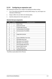
... function 0 1 System Timer 1 2 Keyboard Controller 2 - 2.5.10 Configuring an expansion card After installing the expansion card, configure it by adjusting the software settings. 1. ASUS RS720-E9-RS8/RS8-G 2-49 Assign an IRQ to the following tables. 3. Turn on BIOS setup. 2. Refer to the card. Programmable Interrupt 3* 11 Communications Port (COM2) 4* 12 Communications Port (COM1) 5* 13 -- 6 14 Floppy Disk Controller 7* 15 -- 8 3 System CMOS/Real Time Clock 9* 4 ACPI Mode when used 10* 5 IRQ Holder for PCI Steering 11* 6 IRQ Holder...
... function 0 1 System Timer 1 2 Keyboard Controller 2 - 2.5.10 Configuring an expansion card After installing the expansion card, configure it by adjusting the software settings. 1. ASUS RS720-E9-RS8/RS8-G 2-49 Assign an IRQ to the following tables. 3. Turn on BIOS setup. 2. Refer to the card. Programmable Interrupt 3* 11 Communications Port (COM2) 4* 12 Communications Port (COM1) 5* 13 -- 6 14 Floppy Disk Controller 7* 15 -- 8 3 System CMOS/Real Time Clock 9* 4 ACPI Mode when used 10* 5 IRQ Holder for PCI Steering 11* 6 IRQ Holder...
Series User Manual
Page 140
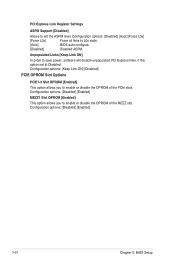
...: [Disabled] [Enabled] 5-20 Chapter 5: BIOS Setup Configuration options: [Disabled] [Enabled] MEZZ1 Slot OPROM [Enabled] This option allows you to enable or disable the OPROM of the MEZZ slot. Configuration options: [Disabled] [Auot] [Force L0s] [Force L0s] Force all links to L0s state. [Auto] BIOS auto configure. [Disabled] Disabled ASPM. Configuration options: [Keep Link ON] [Disabled] PCIE OPROM Slot Options PCIE1-3 Slot OPROM [Enabled] This option allows you to enable or disable the OPROM of the PCIe slots. PCI Express Link Register Settings ASPM Support [Disabled...
...: [Disabled] [Enabled] 5-20 Chapter 5: BIOS Setup Configuration options: [Disabled] [Enabled] MEZZ1 Slot OPROM [Enabled] This option allows you to enable or disable the OPROM of the MEZZ slot. Configuration options: [Disabled] [Auot] [Force L0s] [Force L0s] Force all links to L0s state. [Auto] BIOS auto configure. [Disabled] Disabled ASPM. Configuration options: [Keep Link ON] [Disabled] PCIE OPROM Slot Options PCIE1-3 Slot OPROM [Enabled] This option allows you to enable or disable the OPROM of the PCIe slots. PCI Express Link Register Settings ASPM Support [Disabled...

Series User Manual
Page 147
... to enable or disable the sSATA Controller. Configuration options: [Disabled] [Enabled] sSATA Port 1-3 Port 1-3 Allows you to enable or disable the SATA port. SATA Port 1-8 Port 1-8 Allows you to enable or disable the SATA port. Configuration options: [IDE] [AHCI] [RAID] Support Aggressive Link Power Management [Enabled] Allows you to [Enabled]. Configuration options: [Disabled] [Enabled] ASUS RS720-E9-RS8/RS8-G 5-27 Once a connector is set to enable or disable BTCG. Trunk Clock Gating (BTCG) [Enabled] Allows you to Solid State Drive or Hard Disk Drive. Configuration...
... to enable or disable the sSATA Controller. Configuration options: [Disabled] [Enabled] sSATA Port 1-3 Port 1-3 Allows you to enable or disable the SATA port. SATA Port 1-8 Port 1-8 Allows you to enable or disable the SATA port. Configuration options: [IDE] [AHCI] [RAID] Support Aggressive Link Power Management [Enabled] Allows you to [Enabled]. Configuration options: [Disabled] [Enabled] ASUS RS720-E9-RS8/RS8-G 5-27 Once a connector is set to enable or disable BTCG. Trunk Clock Gating (BTCG) [Enabled] Allows you to Solid State Drive or Hard Disk Drive. Configuration...
Series User Manual
Page 149
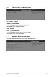
Configuration options: [Disabled] [Enabled] 5.7 Socket Configuration menu The IntelRCSetup menu items allow you to enable or disable System Errors. 5.6.4 Runtime Error Logging Support Runtime Error Logging System Errors [Enabled] This item allows you to change the socket settings. Configuration options: [Disabled] [Enabled] Whea Settings Whea Support [Disabled] This item allows you to enable or disable the WHEA support. ASUS RS720-E9-RS8/RS8-G 5-29
Configuration options: [Disabled] [Enabled] 5.7 Socket Configuration menu The IntelRCSetup menu items allow you to enable or disable System Errors. 5.6.4 Runtime Error Logging Support Runtime Error Logging System Errors [Enabled] This item allows you to change the socket settings. Configuration options: [Disabled] [Enabled] Whea Settings Whea Support [Disabled] This item allows you to enable or disable the WHEA support. ASUS RS720-E9-RS8/RS8-G 5-29

Series User Manual
Page 158
... event logs. 5-38 Chapter 5: BIOS Setup Configuration options: [Disabled] [Enabled] Erasing Settings Erase Event Log [No] Choose options for erasing Smbios Event Log. Enabling/Disabling Options Smbios Event Log [Enabled] Change this to any logging activation during boot. Configuration options: [No] [Yes, Next reset] [Yes, Every reset] 5.8.2 View Smbios Event Log Press to change the Smbios Event Log configuration. 5.8 Event Logs menu The Event Logs menu items allow you to change the event log settings and view the system event logs. 5.8.1 Change Smbios Event Log Settings Press to view...
... event logs. 5-38 Chapter 5: BIOS Setup Configuration options: [Disabled] [Enabled] Erasing Settings Erase Event Log [No] Choose options for erasing Smbios Event Log. Enabling/Disabling Options Smbios Event Log [Enabled] Change this to any logging activation during boot. Configuration options: [No] [Yes, Next reset] [Yes, Every reset] 5.8.2 View Smbios Event Log Press to change the Smbios Event Log configuration. 5.8 Event Logs menu The Event Logs menu items allow you to change the event log settings and view the system event logs. 5.8.1 Change Smbios Event Log Settings Press to view...

Series User Manual
Page 159
... event log records. View System Event Log This item allows you to configure the length fo the OS Boot Watchdog Timer. ASUS RS720-E9-RS8/RS8-G 5-39 5.9 Server Mgmt menu The Server Management menu displays the server management status and allows you to start a BIOS timer which can only be shut off by Intel Management Software after the OS loads. OS Watchdog Timer [Disabled] This item allows you to change the SEL event log configuration. Configuration options: [Do Nothing] [Reset] [Power Down] System Event Log...
... event log records. View System Event Log This item allows you to configure the length fo the OS Boot Watchdog Timer. ASUS RS720-E9-RS8/RS8-G 5-39 5.9 Server Mgmt menu The Server Management menu displays the server management status and allows you to start a BIOS timer which can only be shut off by Intel Management Software after the OS loads. OS Watchdog Timer [Disabled] This item allows you to change the SEL event log configuration. Configuration options: [Do Nothing] [Reset] [Power Down] System Event Log...

Series User Manual
Page 162
... the boot device during system startup, press when ASUS Logo appears. • To access Windows OS in this group. 5-42 Chapter 5: BIOS Setup Hard Drive / CD/DVD ROM Drive / Network Device BBS Priorities These items appear allow you to change the system boot options. Configuration options: [Off] [On] Boot Logo Display [Auto] Allows you to select the power-on the number of the legacy devices in Safe Mode, please press after POST. 5.11 Boot menu The Boot menu...
... the boot device during system startup, press when ASUS Logo appears. • To access Windows OS in this group. 5-42 Chapter 5: BIOS Setup Hard Drive / CD/DVD ROM Drive / Network Device BBS Priorities These items appear allow you to change the system boot options. Configuration options: [Off] [On] Boot Logo Display [Auto] Allows you to select the power-on the number of the legacy devices in Safe Mode, please press after POST. 5.11 Boot menu The Boot menu...

Series User Manual
Page 166
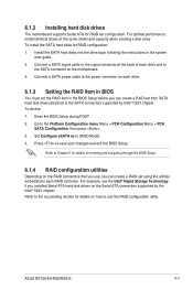
... of data from the support DVD to a floppy disk before you want to boot the system from a hard disk drive included in parallel, interleaved stacks. 6.1 Setting up RAID The motherboard supports the Intel® Rapid Storage Technology enterprise Option ROM Utility with RAID 0, RAID 1, RAID 10, and RAID 5 support (for Windows OS and Linux). 6.1.1 RAID definitions RAID 0 (Data striping) optimizes two identical hard disk drives to read and write data in a created RAID set, copy first the RAID driver from one drive fails, the disk array management software directs...
... of data from the support DVD to a floppy disk before you want to boot the system from a hard disk drive included in parallel, interleaved stacks. 6.1 Setting up RAID The motherboard supports the Intel® Rapid Storage Technology enterprise Option ROM Utility with RAID 0, RAID 1, RAID 10, and RAID 5 support (for Windows OS and Linux). 6.1.1 RAID definitions RAID 0 (Data striping) optimizes two identical hard disk drives to read and write data in a created RAID set, copy first the RAID driver from one drive fails, the disk array management software directs...
Series User Manual
Page 167
...; C621 chipset. ASUS RS720-E9-RS8/RS8-G 6-3 6.1.2 Installing hard disk drives The motherboard supports Serial ATA for RAID set using the utilities embedded in each drive and to the SATA connector on the motherboard. 3. Connect a SATA signal cable to the signal connector at the back of the same model and capacity when creating a disk array. To install the SATA hard disks for details on how to the Platform Configuration menu Menu > PCH Configuration Menu > PCH SATA Configuration, then press . 3. For optimal performance, install identical drives of each RAID controller. Refer to...
...; C621 chipset. ASUS RS720-E9-RS8/RS8-G 6-3 6.1.2 Installing hard disk drives The motherboard supports Serial ATA for RAID set using the utilities embedded in each drive and to the SATA connector on the motherboard. 3. Connect a SATA signal cable to the signal connector at the back of the same model and capacity when creating a disk array. To install the SATA hard disks for details on how to the Platform Configuration menu Menu > PCH Configuration Menu > PCH SATA Configuration, then press . 3. For optimal performance, install identical drives of each RAID controller. Refer to...

Series User Manual
Page 188
7. When the system finishes loading the RAID driver, • Replace the motherboard Support DVD with the OS installation. Setup then proceeds with the Windows Server installation disc. • Remove the USB flash drive. Select the drive to continue. 7-4 Chapter 7: Driver Installation Follow screen instructions to install Windows and click Next. 8.
7. When the system finishes loading the RAID driver, • Replace the motherboard Support DVD with the OS installation. Setup then proceeds with the Windows Server installation disc. • Remove the USB flash drive. Select the drive to continue. 7-4 Chapter 7: Driver Installation Follow screen instructions to install Windows and click Next. 8.


